Seamless and non-repetitive 4D texture variation synthesis and real-time rendering for measured optical material behavior - Fraunhofer IGD
←
→
Page content transcription
If your browser does not render page correctly, please read the page content below
Computational Visual Media
 https://doi.org/10.1007/s41095-019-0141-4                                          Vol. 5, No. 2, June 2019, 161–170

 Research Article

Seamless and non-repetitive 4D texture variation synthesis and
real-time rendering for measured optical material behavior

Martin Ritz1 ( ), Simon Breitfelder2 , Pedro Santos1 , Arjan Kuijper1,2 , and Dieter W. Fellner1,2,3


c The Author(s) 2019.

Abstract We show how to overcome the single weakness                   Keywords optical material behavior; reflectance
of an existing fully automatic system for acquisition                           modeling; 4D texture synthesis; texturing
of spatially varying optical material behavior of real
object surfaces. While the expression of spatially varying             1   Introduction and related work
material behavior with spherical dependence on incoming
light as a 4D texture (an ABTF material model) allows                  3D rendering research is continuously striving to come
flexible mapping onto arbitrary 3D geometry, with                       closer to a physically realistic representation of real-
photo-realistic rendering and interaction in real time,                world surfaces, as it is ever more widely applied to
this very method of texture-like representation exposes                fields where a high degree of realism is required (e.g.,
it to common problems of texturing, striking in two                    the 3D games industry) or where rapid prototyping
disadvantages. Firstly, non-seamless textures create                   is applied in early stages of design (e.g., in the
visible artifacts at boundaries. Secondly, even a perfectly            automotive and textile industries). The approach
seamless texture causes repetition artifacts due to                    of measuring ABTFs (approximate bi-directional
their organised placement in large numbers over a 3D                   texturing functions) [1, 2] is one way to avoid the
surface. We have solved both problems through our                      need for synthetic design of material models, as it
novel texture synthesis method that generates a set of                 used to be the standard for a long time even though
seamless texture variations randomly distributed over                  requiring significant manual effort. ABTFs were first
the surface at shading time. When compared to regular                  proposed by Ref. [1], who used a quarter light arc
2D textures, the inter-dimensional coherence of the 4D                 with incident illumination from point lights, mounted
ABTF material model poses entirely new challenges                      at angles ranging from zero elevation (grazing angles
to texture synthesis, which includes maintaining the                   onto the material surface) up to nearly vertically
consistency of material behavior throughout the 4D                     incident light directions. The acquisition of optical
space spanned by the spatial image domain and the                      material behavior, while already spatially varying
angular illumination hemisphere. In addition, we tackle                due to the matrix sensor of the camera, relied on the
the increased memory consumption caused by the                         assumption of isotropy, meaning that the material
numerous variations through a fitting scheme specifically              sample response is not affected by its rotation around
designed to reconstruct the most prominent effects                      its surface normal. The resulting ABTF data
captured in the material model.                                        consisted of two spatial dimensions (within the sample
                                                                       surface) and one dimension for light variation, leading
                                                                       to three dimensions in total. Many materials cannot
1 Fraunhofer IGD, Darmstadt, 64283, Germany. E-mail:                   be faithfully represented by assuming isotropy, as they
  M. Ritz, martin.ritz@igd.fraunhofer.de ( ); P. Santos,               are a combination of many different materials each
  pedro.santos@igd.fraunhofer.de; A. Kuijper, arjan.kuijper@
                                                                       with different physical structure, and thus reacting
  igd.fraunhofer.de; D. Fellner, dieter.fellner@igd.fraunhofer.de.
2 TU Darmstadt, Darmstadt, 64289, Germany. E-mail:
                                                                       differently at each individual surface point to changes
  simon.breitfelder@gmail.com.                                         of the incoming light direction around the surface
3 TU Graz, Graz, 8010, Austria.                                        normal. Thus, an additional dimension of incoming
Manuscript received: 2019-03-20; accepted: 2019-03-29                  light direction was added in Ref. [2]. By using a

                                                                 161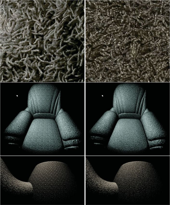
162                                                                                    M. Ritz, S. Breitfelder, P. Santos, et al.

turntable which rotates the sample around its surface             according to the angle of the virtual light source
normal under the camera, 4D ABTF model results                    in the scene in relation to the surface normal and
from combining the two lateral dimensions with two                the current U –V coordinates specified to the shader
angular dimensions describing the hemisphere of                   during rendering of the current fragment, provided
incident light directions. Also, the acquisition process          by the texture mapping of the 3D geometry to be
was entirely automated and reduced to only a few                  rendered. The texture-based nature of the ABTF
minutes per sample. Effectively, the combinatorial                 model allows for arbitrary mapping onto any 3D
use of rotary and quarter light arc leads to an                   geometry with free choice of scaling and orientation,
illumination hemisphere with the camera at its center,            and the abstraction from multiple observer directions
looking vertically down on the sample. The ABTF                   allows the model to fit into current graphics memory
material model acquired and rendered with the                     for real-time rendering.
technique in Ref. [2] represents actually captured                   Despite this abstraction, the material model
real-world material behavior as a 4D texture that can             provides compelling results for most materials, while
be rendered in real time. By only considering one                 shortcomings only arise where material behavior
perspective vertically above the sample, it provides              actually depends on the observer direction, for
an abstraction of the higher dimensional 6D BTF (bi-              instance for materials with a “chameleon” effect
directional texturing function) [3] that captures the             that change colors depending on the viewing angle.
spatially varying material behavior of flat materials,             However, the texture-like nature of the model shares
discretized to the resolution of a matrix sensor (2D),            common texturing problems, which becomes apparent
for all combinations of incoming light (2D) and                   on two levels. Firstly, if single layers in the 4D
outgoing observer direction (2D), while preserving                texture stack are not synthesized to be seamless,
the dependence on the incoming light direction.                   border artifacts become apparent in the form of
   Figure 1 puts the ABTF model within the context                spatial discontinuities along the seams across texture
of the taxonomy of surface reflectance functions. It               units. Secondly, even a perfectly synthesized seamless
is represented by a two-dimensional stack of images               texture causes repetition artifacts that strike the eye
(layers), each of which expresses the spatially varying           when large numbers of identical patches are placed
material behavior on the sample surface for one                   side-by-side over the 3D surface once they are visible
specific incoming light direction. Rendering is done               within the field of view at the same time. These
by the shader accessing the captured image stack,                 two unsolved problems are the ones addressed by

Fig. 1 ABTF model in the surface reflectance function taxonomy introduced in Ref. [4], derived from BTFs and depending on the same
variables as surface reflectance functions (SRF), but with different semantics.
Seamless and non-repetitive 4D texture variation synthesis and real-time rendering for measured optical material behavior 163
this work. small patches from an input image to different
Our solution to both problems is a novel texture new locations within the newly synthesized texture
synthesis approach that first makes the single ABTF while maintaining optical similarity at the transitions
texture layers seamless, and in a second step generates within overlapping regions of neighboring patches.
a set of variations for each layer. The patch variations We extended it by adding initial reassembly phases
are precomputed and randomly distributed on the before the original process, ensuring periodicity at
surface at shading time, thus completely disrupting the boundary regions of the texture to be synthesized
any regular patterns and entirely removing repetition so that it can be seamlessly concatenated border to
artifacts, generating the impression of a non-repeating border in both dimensions. Most importantly, we use
artifact-free surface (see Fig. 2). the output of the algorithm not just to generate a
For the domain of 2D texturing, there are new patch placement distribution for one texture, but
approaches that solve these challenges [5, 6]. However, instead for a non-deterministically generated set of
we are dealing with inter-dimensional coherence patch transfer prescriptions consistently applied to all
within a 4D texture, posing the strong requirement of ABTF data set layers, which guarantees consistency
maintaining consistency across the multi-dimensional across different incident light angles and provides
space of measured material behavior information, a random patch placement every time to avoid
represented by the spatial domain and the two repetition artifacts.
dimensions defined by a hemisphere of incoming The algorithm starts with an empty destination
light directions. This introduces challenges such as texture matching the input image dimensions. It
specular highlight responses for which continuity must consists of four phases, visualized in Fig. 3.
be ensured during realignment of texture sub-regions. • Phase 1: Patches are placed at all corners to
Finally, generating multiple variations per ABTF ensure periodicity, which is achieved by choosing
layer increases memory consumption. We counter this a random source patch and splitting it vertically
problem using a fitting scheme specifically designed and horizontally through its center for transfer to
to reconstruct the most prominent effects captured diagonally opposing corners of the target texture.
by the material model. As the inner patch split edges coincide with the
respective outer texture edges, appending the
2 Technical approach target texture at any edge reunites the original
patch, thus leading to artifact-free periodicity for
2.1 Texture synthesis and periodization the corner pieces.
The synthesis method for measured ABTF materials • Phase 2: A similar idea is followed to fill
developed in this work is based on image quilting the horizontal edges of the target texture, with
[7], which assembles a new texture by transferring two differences. Firstly, the source patch to be
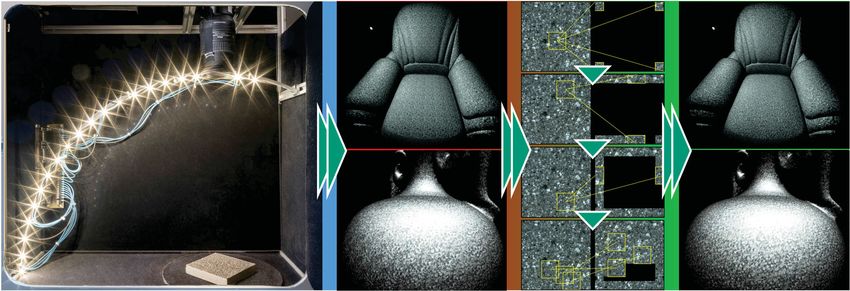
Fig. 2 From measured optical material behavior (4D textures with seams and repetitions) via synthesis of a set of seamless and non-repetitive
4D texture variations to real-time 3D rendering on arbitrary 3D geometry, without texturing artifacts.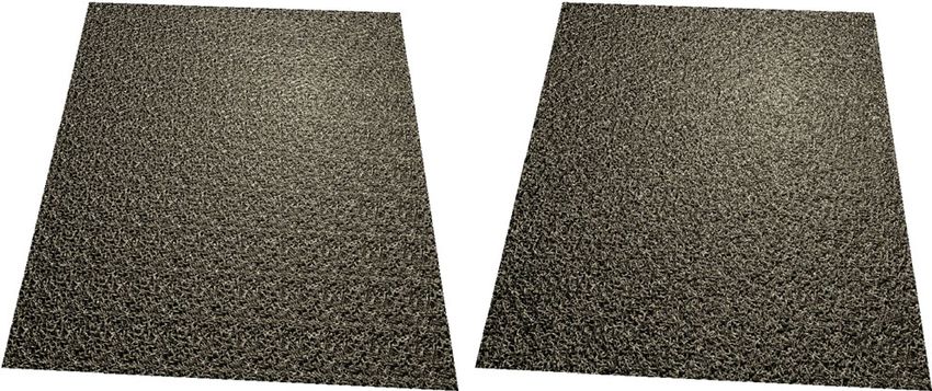
164                                                                                      M. Ritz, S. Breitfelder, P. Santos, et al.

                                                                    while for an ABTF dataset, consistency throughout
                                                                    the 4D texture must be maintained to avoid visual
                                                                    artifacts caused by inconsistencies between texture
                                                                    layers captured with different lighting directions, so a
                                                                    suitable image space must be chosen that represents
                                                                    the entire ABTF dataset.
                                                                       In Ref. [8] a BTF dataset is represented by a
                                                                    height map computed from all images captured,
                                                                    representing the approximate geometry of the surface.
Fig. 3 Visualization of phases 1–4 of the algorithm. Left: source   In addition to the height map, we compute a diffuse
image. Right: synthesized texture.
                                                                    map and a reflectance map (see Fig. 4). The
                                                                    three images represent the most relevant aspects
  transferred is now horizontally split into two halves             of the entire ABTF dataset and are combined by
  which then are transferred to vertically opposing                 weighted per-pixel summation into one reference
  edges of the target texture, ensuring periodicity                 image ΔR, serving as source image space. During
  as in Phase 1. Secondly, to avoid deterministic                   patch transfer, the impact of the respective diffuse,
  behavior, the patch to be transferred is now chosen               height, and reflectance component contributions is
  at random from a set of best matching patches.                    controlled by weights. Computing ΔI is the most
  Best matches are determined based on the optical                  computationally intensive step, as it has to be done
  similarity between a patch and the existing target                for each overlapping region evaluated during the
  neighborhood measured in their common region of                   search for best matches. The algorithm described
  overlap, as explained in detail in Section 2.3.                   in Section 2.1 has to run in the serial order described,
• Phase 3: Steps analogous to Phase 2 are per-                      as subsequent patch placement is dependent on
  formed to fill the vertical edges while ensuring                   previously placed patches. The sole purpose of the
  periodicity.                                                      reference image R is to serve as basis for generation of
• Phase 4: The inner area of the target texture is                  a set of transfer prescriptions, which are then applied
  filled following a row-major traversal scheme. A                   identically to each texture layer in the ABTF dataset.
  set of best matching source patches is determined                    The diffuse map is the normalized sum of all images
  for each empty block, of which one is chosen for                  captured for each lighting direction. The surface
  transfer at random. Again, as in Phases 2 and 3,                  geometry is represented by a height map which is
  optical similarity is used as a metric to establish               computed in two steps. Firstly, a normal map is
  the most continuous spatial transition across seams               estimated by evaluating the strongest response for
  within the target patch neighborhood.                             each pixel over all lighting directions. The vectors
  Parameters for this algorithm are: the set size for               computed here do not generally represent the surface
best matches, the block size of texture patches to be               normal, but the averaged direction to the strongest
transferred, and the degree of overlap between a patch              incoming light contribution. This difference only
candidate and its existing destination neighborhood.                applies to strongly reflective materials, while there
                                                                    is no difference for perfectly diffuse materials. The
2.2    Visual similarity metric
                                                                    height map follows in the second step from integration
The metric used to determine optical similarity to                  of the normal map [9]. The reflectance map of the
guide the process of finding best matching patches
for transfer (see Section 2.3) is a monochrome error
image ΔI (see Fig. 5(1), gray scale region), covering
exactly the area of overlap currently considered. The
intensity for each pixel is computed as the sum of
squared differences between source and destination
image space for the three color channels evaluated at               Fig. 4 Left: single example image from the ABTF dataset. Right:
                                                                    reference image components for patch transfer guidance based on
that pixel position. For 2D textures, the texture                   optical error, derived from the entire ABTF dataset to represent
is the source image space for this computation,                     surface structure and material behavior.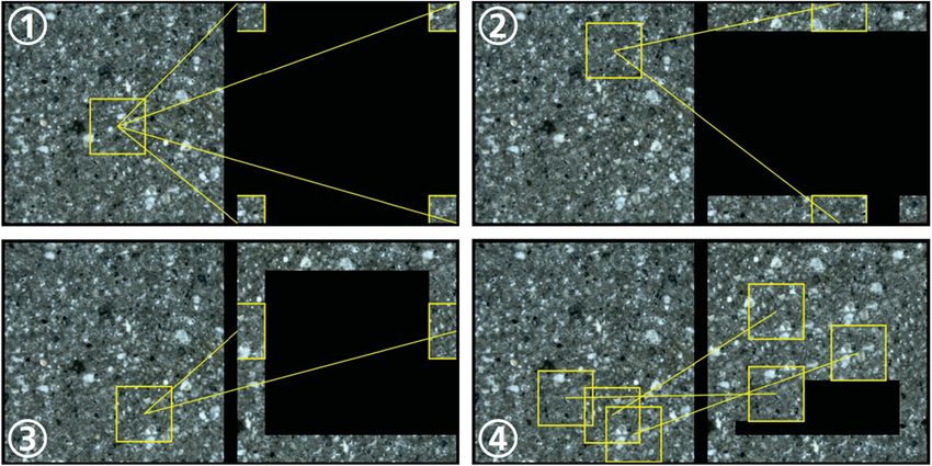
Seamless and non-repetitive 4D texture variation synthesis and real-time rendering for measured optical material behavior 165

surface is computed by comparing two normal maps
weighted with different exponents to find strongly
reflective areas on the surface.
2.3    Seamless transfer
                                                                   Fig. 6 Optical error image ΔI (1); possible minimal paths through
Naive copying of rectangular areas leads to highly                 the four edge-regions (2); paths with minimal cost (3); the four
                                                                   path segments (endpoints yellow) are connected (4); resulting cyclic
noticeable edges at the boundaries even if the general             boundary cut (5).
structure fits the local neighborhood (see Figs. 5(1)
and 5(2)). Image quilting reduces this effect by
                                                                      To improve the resulting image quality, the
allowing a free-form boundary cut which minimizes
                                                                   boundary cut is not used as a hard edge between
optical differences between source patch and target
                                                                   patch content and existing destination neighborhood.
environment (see Figs. 5(3) and 5(4)). Optical
                                                                   Instead, blur masks are created for the areas inside
differences are expressed by the error image ΔI
                                                                   and outside the boundary cut using Gaussian blurring
introduced in Section 2.2, which at the same time
                                                                   (see Fig. 7). The patch content and the neighborhood
works as a mask, excluding all pixels set to zero
                                                                   background are then combined by weighting their
(black) from the error metric (see Fig. 5(1)).
                                                                   respective masks, leading to a smooth transition.
   Finding the free-form boundary cut following the
                                                                      As the resulting texture is generated iteratively,
path with the minimum cumulative error in ΔI is
                                                                   some regions do not yet contain data and thus do
a path-finding problem which can be solved using
                                                                   not provide a basis for error computation, e.g., the
Dijkstra’s algorithm. The algorithm for finding the
                                                                   black region in the example in Fig. 8(left). When
free-form boundary cut presented here computes
                                                                   placing a patch at the right border region the overlap
many path candidates in a set of sub-regions of ΔI.
                                                                   error can be computed only for the region of overlap
Every pixel in a sub-region represents a node in the
                                                                   in the center of Fig. 8(middle, shown as grayscale
Dijkstra graph. Interconnections are generated for all
                                                                   error image). As the error for all paths through yet
adjacent pixels (only horizontally and vertically, not
                                                                   undefined (empty) regions is 0, the decision for the
diagonally) using the average error (i.e., intensity
                                                                   best path is ambiguous and can yield bad results.
value in ΔI) between both pixels as cost. The
                                                                   The red line in Fig. 8(middle, above) represents the
inner region is masked out (see the black square
                                                                   path with minimal error, but does not consider the
in the center of Figs. 5(1), 5(3), and 6) as this part
                                                                   entire viable area within the existing neighborhood,
of the patch is adopted unchanged and must thus
                                                                   resulting in visible discontinuity artifacts highlighted
not be crossed by the boundary cut. At first, only
                                                                   by the red rings in the resulting texture in Fig. 8(right,
the sub-regions at the left, top, right, and bottom
                                                                   above). We solve this problem by introducing border-
edges are considered. All combinations of start and
                                                                   flags for the main directions left, top, right, and
end points on the yellow lines for each of the four
                                                                   bottom, that force the path-finding algorithm to
highlighted regions are evaluated using Dijkstra’s
                                                                   enclose the full region inside the boundary cut towards
algorithm, leading to the path with minimum cost for
                                                                   the directions indicated by the respective flags. The
the next step (see Figs. 6(2) and 6(3)). The endpoints
                                                                   boundary cut in Fig. 8(middle, below) results from
of the selected paths (yellow in Fig. 6(4)) are then
                                                                   setting the top and bottom border-flags, leading to
connected through the corner-regions which requires
                                                                   a soft transition between both patches as during
only one evaluation of Dijkstra’s algorithm per corner.
                                                                   computation of the optimal path, the entire border
The full cyclic path (see Fig. 6(5)) represents the
                                                                   region is considered as visible in Fig. 8(right, below).
minimum error boundary cut.

Fig. 5 Optical error image ΔI (1); naive transfer of rectangular   Fig. 7 Boundary cut used to draw a filled polygon defining the
patch exposing visual discontinuities (2); minimum boundary cut    weight of the patch content to smooth the transition using Gaussian
through optical error field (3); transfer of boundary region (4).   blur.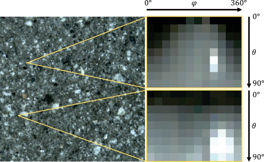
166                                                                                         M. Ritz, S. Breitfelder, P. Santos, et al.

                                                                      Fig. 10 Tiles incompatible at common corner despite compatible
                                                                      edges, solved by enforcing common corners.
Fig. 8 Border flags controlling the extent of the region considered
by visual matching during patch placement. Left: initial coverage
with undefined regions on the right. Middle: error image in overlap
                                                                      gives a schematic overview of the corner compatibility
region (grayscale) and two possible candidates for the boundary cut
assigned the same cost in the yet empty areas of the canvas. The      within a set of 16 tile variations, where compatibility
upper candidate does not consider the neighboring regions above and   between neighboring tiles is expressed by matching
below the existing patch, while the lower candidate is aware of the
unset regions. Right: difference in results.
                                                                      color. Compatibility between neighboring tiles is
                                                                      strongly limited by edge compatibility and is only
                                                                      given for a subset of the tile set.
2.4    Variation synthesis and rendering                                 A pseudo-random number generator implemented
Periodic regular textures can be mapped to large                      in the shader as a hash function guarantees random
surfaces back to back without visible repetition                      selection of variations for mapping on the surface
artifacts, but in the case of irregular and stochastic                during rendering while keeping the overall mapping on
textures, highly noticeable periodic patterns as in                   the entire object surface constant without the need to
Fig. 9(left) appear. This problem can be handled                      store the chosen assignment of variations. Accessing
by generating tile sets, within which certain com-                    texture patches at rendering time requires consistency,
binations of elements are periodic, and the variation                 since texture variations once chosen and mapped to a
of different combinations can be used to fill a regular                 rendered part of the object must be chosen identically
grid and thus create a textured surface without visible               each subsequent time the respective area is rendered.
seams and repetitions. Many tile sets are based on                    We use a pseudo-random number generator to satisfy
Wang tiles [5] that define different types of edges and                 this requirement. The generator works similar to a
compute a tile for every combination of edge types                    hash function that serves as deterministic, surjective
so that there is always a compatible tile for a specific               function, assigning always the same function values to
neighborhood of adjacent edges. Only tiles with the                   the same parameters, but potentially also assigning
same type (types visualized in Fig. 10 in different colors)           the same function value to different parameters. This
can be placed next to each other to share one edge.                   is acceptable as the number of texture variations is
  The variation synthesis technique introduced in                     limited and has to be reused multiple times across the
this work generates a corner-based tiling similar to                  object surface. The generator accepts an initial seed
colored corners tiling [10]. A complete tile set created              value that can be used to control the texture variation
using V corner types yields V 4 tiles in total. Already               distribution and easily generate different renderings
using V = 2 leads to 16 tiles which removes repetition
artifacts, as the comparison in Fig. 9 shows. Figure 11

                                                                      Fig. 11      Abstract tile set of minimum size based on 2 corner
Fig. 9 Left: periodic pattern caused by repeating the same texture    types (red and black), leading to 16 variations, indicating corner
10 times in both dimensions. Right: the same tiling rendered with     compatibilities (above). Example of 2 × 2 neighborhood construction
randomly distributed seamless texture variations.                     (below).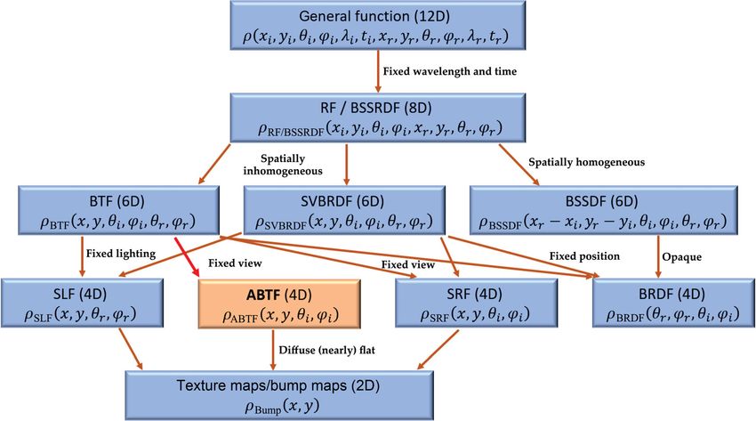
Seamless and non-repetitive 4D texture variation synthesis and real-time rendering for measured optical material behavior 167

using the same input texture and 3D model. The
available texture patch variations are addressed using
U –V mapping, where multiples of the default range
[0, 1] allow addressing of the virtual array of texture
variations (see Fig. 12).
2.5    Fitting
                                                                        Fig. 13 Left: visualization of reflectance behavior for one pixel for
The smallest possible tile set using V = 2 corner types                 full angular spectrum (light source elevation θ and rotation angle ϕ).
                                                                        Right: HSL color spectrum.
(V = 1 is equivalent to a single periodic texture) leads
to 24 = 16 texture variations in total (see Fig. 11).
The total memory consumption depends on the image
resolution W × H and the sampling density of the
virtual lighting hemisphere, expressed by R rotations
of the sample and E discrete elevations of the light
source, and amounts to M = 3W × H × R × E bytes.
The data sets used in this work range from 300 MB
to 1 GB, which leads to a total memory consumption
of 4.7–16 GB including all texture variations. This
amount exceeds typically available graphics memory
and also would result in poor frame rates because of
the lack of memory locality, as the renderer needs to                   Fig. 14 Reflectance functions for single pixels. Left: image captured
access a widespread range of data when the surface is                   at ϕ = 90◦ , θ = 79◦ . Right: corresponding reflectance functions for
rendered under varying illumination. The key to real-                   the two highlighted pixels.

time processing of large tile sets is thus compression.
We use a fitting scheme we designed explicitly for                       HLS for the entire 2D illumination space. Similarly,
this challenge. We limit the memory consumption                         saturation remains mostly unaffected for changing
for V = 2 corner types, or 16 texture variations, per                   illumination directions. This observation allows us
ABTF data set to under 2 GB by fitting an analytic                       to set hue and saturation constant. The reason why
model based on the HSL color space (Fig. 13(right)).                    we use the HLS model rather than HSV or similar
The choice of this specific color space for fitting                       color models is that the lightness value alone controls
enables reconstruction of the reflectance behavior for                   the transition from black via color to white, while
each single pixel on the sample surface (Fig. 13(left))                 in other models, this transition requires changing
without visual degradation.                                             further parameters such as the saturation value.
  Analysis of the reflectance function for different                        The lightness value for the two-dimensional lighting
pixels (Fig. 14), transformed into HLS color space,                     direction (azimuth, elevation) is reconstructed using
confirms that hue remains mostly constant over the                       six parameters per azimuth light angle, plus two
entire spectrum of incident illumination angles as can                  parameters for hue and saturation, for every pixel.
be seen in Fig. 15 for one specific pixel, evaluated in

Fig. 12    Left: different texture variations Tu,v side by side with     Fig. 15 Lightness curves of a pixel for different angles of rotation
shared corners Ci,j . Right: texture patches are addressed using U –V   in HSL color space. Note how hue (red) and saturation (blue) remain
mapping. Different variations are accessible by using multiples of the   almost constant. The deviation in the graph is due to the specular
default range [0, 1].                                                   highlight at the respective position.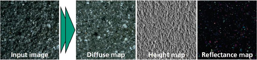
168 M. Ritz, S. Breitfelder, P. Santos, et al.
In compressed form the tile sets fit into typically
available graphics memory and can thus be rendered
in real time.
A visual comparison for two rendered 3D models
mapped with two different physically measured ABTF
material samples processed by this method is given
in Fig. 16. The renderings on the left were generated
based on the original uncompressed ABTF dataset
(reference), shown side by side with a rendering
using the same settings, but this time evaluating the
compressed dataset after applying the fitting scheme
described (final output of the algorithm shown).
The only perceivable visual difference is a slight
discrepancy in hue. The reason for this effect is a
consequence of the assumption that for all variations
of incoming light directions, the hue channel of the
material response expressed in the HLS color model
remains mostly constant, which is only approximately
the case as can be seen in Fig. 15(red curve).
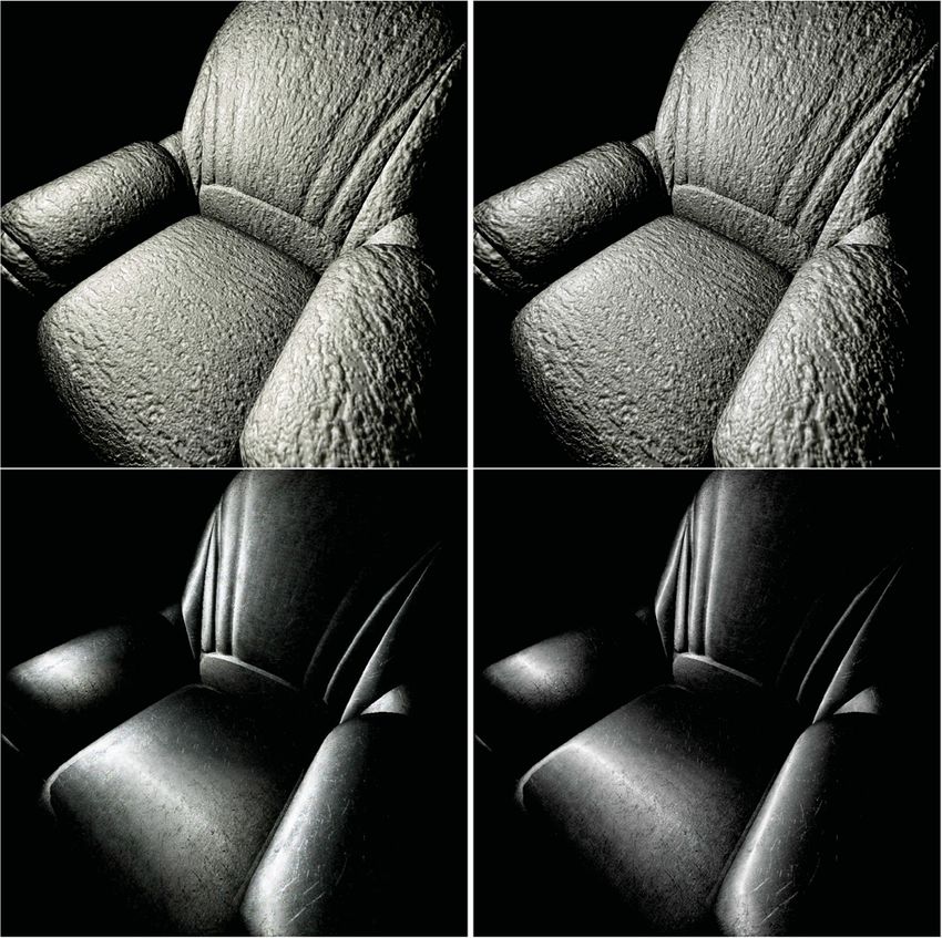
Fig. 17 3D rendering of the ABTF material model. Left: state of
the art before this work. Right: our results. Above: plane mapped
with 2 × 2-tiled texture, showing clear discontinuity boundaries at the
seams, that are entirely removed by our solution. Center: armchair
model mapped with multi-repetition stone texture. Our results do
not show any repetition artifacts. Below: teapot model mapped with
carpet texture, exposing repetitions of identical textures, while our
result seems to consist of one non-repetitive texture only.
transferring small patches from an input image
of identical dimensions to different new locations
within the new image while maintaining optical
similarity within overlapping regions of neighboring
patches. We extended it by adding initial reassembly
phases during which the target texture is made
periodic at its boundary regions so that it can be
seamlessly concatenated border to border in both
dimensions. Most importantly, we use the output
Fig. 16 Visual comparison of original (left) and compressed (right) of the algorithm not just to generate a new patch
ABTF datasets, captured from two different physical material samples placement distribution for one texture, but instead
“Ingrain” (above) and “Metal” (below). Both material samples feature
a wide spectrum of optical effects like self shadowing and anisotropic
for a non-deterministically generated set of patch
reflections, which are successfully reconstructed by the fitting model transfer prescriptions applied to all ABTF data set
presented in this work. layers, which both guarantees consistency for different
light angles and provides a random patch placement
for every texture variation to avoid repetition
3 Results
artifacts. The consequence of using an entire set
The synthesis method for measured ABTF material of texture variations for all different illumination
models developed in this work is based on image angles is respective increase in memory consumption.
quilting [7] which assembles a new texture by Exploiting the fact that only one dimension is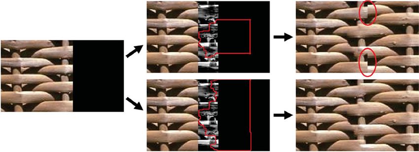
Seamless and non-repetitive 4D texture variation synthesis and real-time rendering for measured optical material behavior 169

significantly affected in HLS color space by changes in           References
the direction of incident illumination, we compensate
                                                                  [1] Kautz, J.; Sattler, M.; Sarlette, R.; Klein, R.; Seidel,
for the increased memory consumption by a novel
                                                                      H.-P. Decoupling BRDFs from surface mesostructures. In:
fitting scheme. Consequently, the reflectance behavior
                                                                      Proceedings of Graphics Interface 2004, 177–182, 2004.
for each single pixel on the sample surface is
                                                                  [2] Ritz, M.; Santos, P.; Fellner, D. Automated acquisition
reconstructed without visual degradation, while 3D
                                                                      and real-time rendering of spatially varying optical
rendering of models mapped with texture variation-                    material behavior. In: Proceedings of the ACM
based ABTF data sets can still be done in real time.                  SIGGRAPH 2018 Posters, Article No. 33, 2018.
                                                                  [3] Schwartz, C.; Sarlette, R.; Weinmann, M.; Klein, R.
4    Conclusions and future work                                      Dome II: A parallelized BTF acquisition system. In:
                                                                      Proceedings of the Workshop on Material Appearance
We have removed the most significant limitation of
                                                                      Modeling, 2013.
an existing 4D texture-based system for acquiring
                                                                  [4] Weinmann, M.; Klein, R. Advances in geometry and
spatially varying optical material behavior of                        reflectance acquisition (course notes). In: Proceedings
real object surfaces, in that now neither texture                     of the SIGGRAPHAsia 2015 Courses, Article No. 1,
seam artifacts nor repetition artifacts disturb the                   2015.
compelling visual experience when rendering the                   [5] Cohen, M. F.; Shade, J.; Hiller, S.; Deussen, O.
material applied to arbitrary 3D geometries, even                     Wang Tiles for image and texture generation. ACM
if the textures are mapped to large surfaces with                     Transactions on Graphics Vol. 22, No. 3, 287–294, 2003.
many repetitions.                                                 [6] Ng, T. Y.; Wen, C.; Tan, T. S.; Zhang, X.; Kim, Y. J.
   Not only have we extended current work on 2D                       Generating an /spl omega/-tile set for texture synthesis.
texture synthesis by a number of optimizations                        In: Proceedings of the International 2005 Computer
providing more robustness across the different classes                 Graphics, 177–184, 2005.
of textures (regular, near-regular, irregular, and                [7] Efros, A. A.; Freeman, W. T. Image quilting for
stochastic), but we have especially tackled entirely                  texture synthesis and transfer. In: Proceedings of the
                                                                      28th Annual Conference on Computer Graphics and
new challenges posed by the higher dimensionality
                                                                      Interactive Techniques, 341–346, 2001.
and inter-dimensional correlation of 4D ABTF
                                                                  [8] Liu, X.; Yu, Y.; Shum, H.-Y. Synthesizing bidirectional
material texture sets, and compensated for the
                                                                      texture functions for real-world surfaces. In: Proceedings
resulting increase in memory consumption such that
                                                                      of the 28th Annual Conference on Computer Graphics
3D rendering can still be done in real time, just                     and Interactive Techniques, 97–106, 2001.
like with the previous approach, but without causing              [9] Nozick, V.; Ismael, D.; Saito, H. GPU-based
texture artifacts.                                                    photometric reconstruction from screen light. In:
   As future improvements, we see firstly that the                     Proceedings of the 8th Annual International Conference
quality of synthesized tile sets can be automatically                 on Artificial Reality and Telexistence, 242–245, 2008.
adjusted according to the occurence of prominent                 [10] Lagae, A.; Dutré, P. An alternative for Wang tiles:
patterns within the texture that draw the observer’s                  Colored edges versus colored corners. ACM Transact-
attention, since periodicity artifacts depend strongly                ions on Graphics Vol. 25, No. 4, 1442–1459, 2006.
on the texture class. Secondly, to avoid noisy
rendering for very dense tiling due to poor surface
sampling, mipmaps adjusted to texture variations                                      Martin Ritz is deputy head of the
                                                                                      Dept. of Cultural Heritage Digitization
can be used that store a texture pyramid with
                                                                                      at Fraunhofer IGD. Next to technical
increasing resolution to adaptively react to the                                      coordination,      his research targets
sampling resolution.                                                                  acquisition of 3D geometry and optical
                                                                                      material behavior, describing light
Acknowledgements                                                                      interaction of objects for arbitrary
                                                                                      combinations of light and observer
This work was partially supported by the European
                                                                directions. He received his bachelor and master of science
project MAXIMUS (No. FP7-ICT-2007-1-217039) and                 degrees in informatics in 2006 and 2009 from TU Darmstadt,
the German Federal Ministry for Economic Affairs and            respectively, as well as his master of science degree in computer
Energy project CultLab3D (No. 01MT12022E).                      science in 2008 from the University of Colorado at Boulder.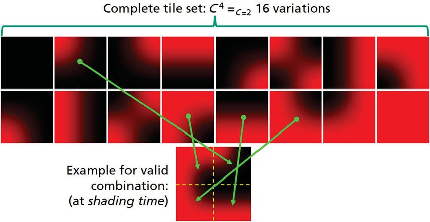
170                                                                                  M. Ritz, S. Breitfelder, P. Santos, et al.

                   Simon Breitfelder completed his                                   Dieter W. Fellner is a professor of
                   bachelor and master degrees in computer                           computer science at TU Darmstadt,
                   science at TU Darmstadt in 2011 and                               Germany, and director of the Fraunhofer
                   2018, respectively.    He focused on                              Institute for Computer Graphics
                   computer graphics topics during his                               Research IGD at the same location since
                   studies and is now working as software                            Oct. 2006. He is still affiliated with the
                   engineer at DENIC eG.                                             Graz University of Technology where
                                                                                     he chairs the Institute of Computer
                                                                Graphics and Knowledge Visualization he founded in
                                                                2005. Dieter W. Fellner’s research activities over the
                  Pedro Santos is head of the Dept.
                                                                last years as documented in more than 370 publications
                  of Cultural Heritage Digitization at
                                                                covered algorithms and software architectures to integrate
                  Fraunhofer IGD. He received his diploma
                                                                modeling and rendering, efficient rendering and visualization
                  and master degrees from the University
                                                                algorithms, generative and reconstructive modeling, virtual
                  of Applied Sciences in Darmstadt,
                                                                and augmented reality, graphical aspects of internet-based
                  Germany and the Technical University
                                                                multimedia information systems and cultural heritage as well
                  of Lisbon, Portugal, respectively. His
                                                                as digital libraries. He is a member of EUROGRAPHICS,
                  research interest is autonomous, color-
                                                                ACM, IEEE Computer Society, and the Gesellschaft fr
calibrated 3D mass-digitization.
                                                                Informatik (GI).

                                                                Open Access This article is licensed under a Creative
                    Arjan Kuijper holds a chair in              Commons Attribution 4.0 International License, which
                    Mathematical and Applied Visual             permits use, sharing, adaptation, distribution and reproduc-
                    Computing at TU Darmstadt and               tion in any medium or format, as long as you give appropriate
                    is a member of the management of            credit to the original author(s) and the source, provide a link
                    Fraunhofer IGD, responsible for scientific   to the Creative Commons licence, and indicate if changes
                    dissemination. He obtained his M.Sc.        were made.
                    degree in applied mathematics from             The images or other third party material in this
                    Twente University and Ph.D. degree          article are included in the article’s Creative Commons
from Utrecht University, both in the Netherlands. He            licence, unless indicated otherwise in a credit line to the
was assistant research professor at the IT University of        material. If material is not included in the article’s
Copenhagen, Denmark, and senior researcher at RICAM in          Creative Commons licence and your intended use is not
Linz, Austria. He obtained his habilitation degree from TU      permitted by statutory regulation or exceeds the permitted
Graz, Austria. He is the author of over 300 peer-reviewed       use, you will need to obtain permission directly from the
publications, associate editor for CVIU, PR, and TVCJ,          copyright holder.
secretary of the International Association for Pattern
Recognition (IAPR) and serves both as reviewer for many           To view a copy of this licence, visit http://
journals and conferences, and as program committee member       creativecommons.org/licenses/by/4.0/.
and organizer of conferences. His research interests cover      Other papers from this open access journal are available
all aspects of mathematics-based methods for computer           free of charge from http://www.springer.com/journal/41095.
vision, graphics, imaging, pattern recognition, interaction,    To submit a manuscript, please go to https://www.
and visualization.                                              editorialmanager.com/cvmj.
You can also read