FAST START TRAINING GUIDE - SIMSOLID 2019 - SIMSOLID FAST START TRAINING
←
→
Page content transcription
If your browser does not render page correctly, please read the page content below
SimSolid FAST START TRAINING

    SimSolid 2019
    Fast Start Training Guide

               All materials © 2015-2018 Altair Engineering Canada Ltd, © 2018 Altair Engineering Inc – All Rights Reserved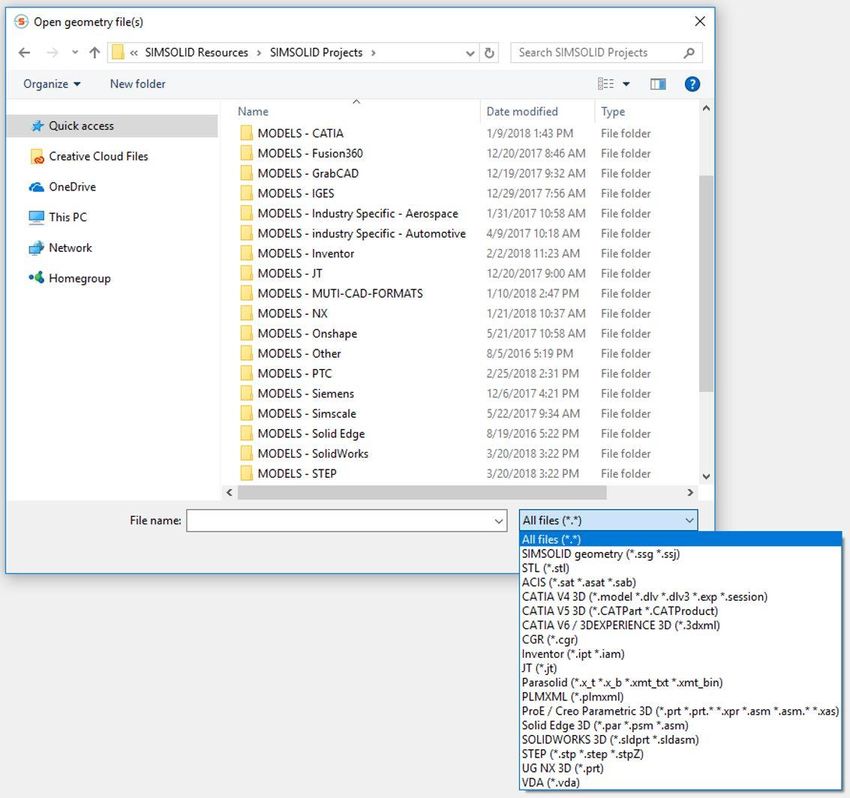
SimSolid FAST START TRAINING

                                   Table of Contents
     •    Section 1 – Introduction
     •    Section 2 – My first analysis
     •    Section 3 – User interface basic concepts
     •    Section 4 – Processing design geometry
     •    Section 5 – Creating an analysis
     •    Section 6 – Interpreting results
     •    Section 7 – Typical SimSolid Workflows
     •    Section 8 – Additional topics and sources for more information

2   12/2/2018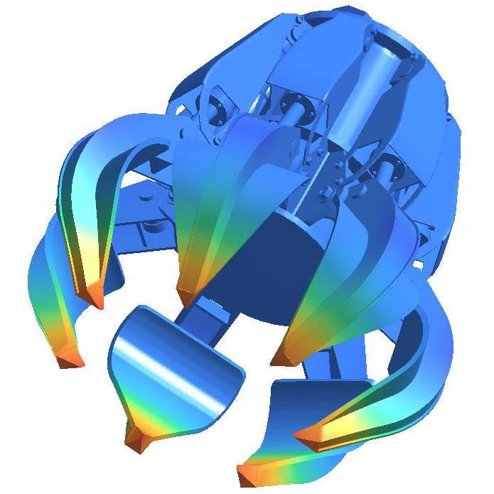
SimSolid FAST START TRAINING

       Section 1

       INTRODUCTION

3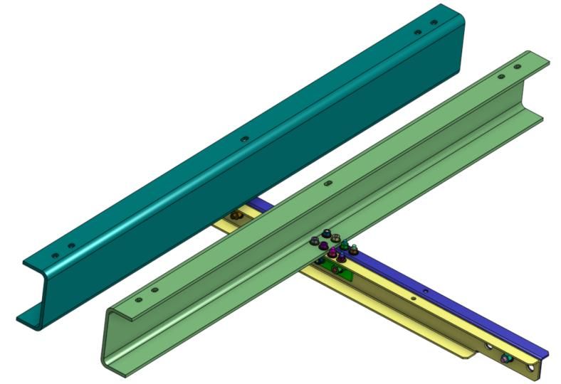
SimSolid FAST START TRAINING

           Welcome to SimSolid, a different kind of FEA
     • SimSolid is a next generation, high capacity, structural FEA
     • It uses new computational methods which operate on original, unsimplified,
       CAD geometry and does not create a mesh
     • SimSolid can solve very large assemblies on a standard desktop computer.
     • SimSolid is the perfect complement to your existing CAE specific or CAD
       embedded Simulation. It extends their analysis range to larger models and
       provides feedback in seconds to minutes

4   12/2/2018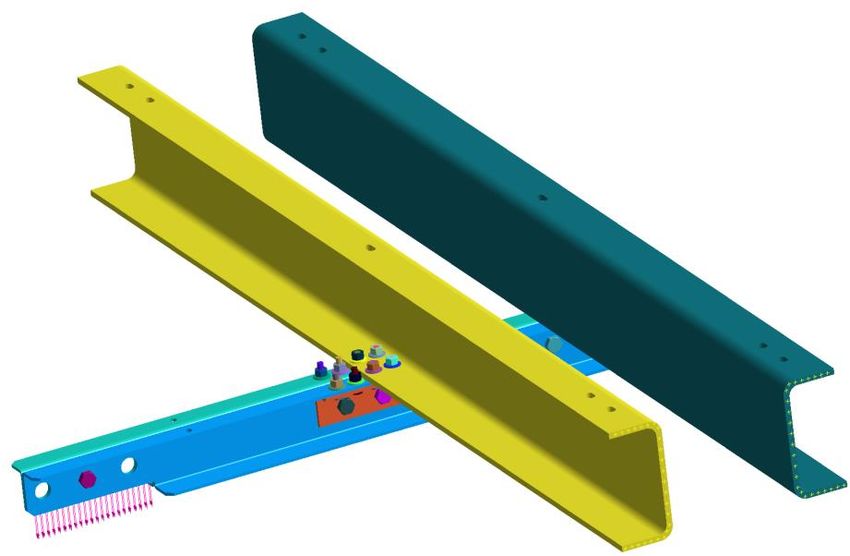
SimSolid FAST START TRAINING

                                  So how do we do it?
     • SimSolid is FEA, but it operates very differently. We do not create a mesh but
       instead use high order functions which are locally adapted to refine the
       solution
     • In the next several slides we provide a little technical background on the
       methods used and how it compares to more traditional FEA
     • We also highlight the technology steps done during each solution pass. Note
       most of this is automated and requires very little input from the user.

                Downloads whitepapers, validation and theory documents and more here

5   12/2/2018
SimSolid compared to traditional FEA - Methods
                    Traditional FEA                                           SimSolid
Simple regions – TET, etc                             Arbitrary regions – whole part can be a region

DOF is associated with a node - it is point-wise      DOF is not point-wise. It can be associated with volumes,
                                                      surfaces, lines and/or point clouds

DOF are nodal Ux, Uy, Uz displacements                DOF are integrals over corresponding geometrical objects,
                                                      not nodal

3 DOF per node                                        Many DOF per single associated geometry object are
                                                      possible, depends on solution adaptation

Boundary compatibility is met exactly                 Boundary compatibility is met approximately and is
                                                      adjusted during solution passes

Shape functions are simple low degree interpolation   Shape functions can be of arbitrary class and are derived
polynomials                                           during the solution phase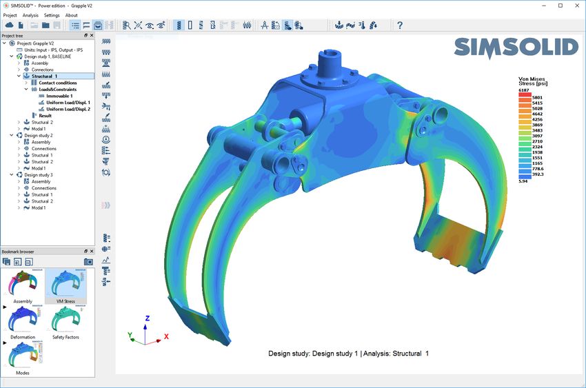
SimSolid compared to traditional FEA - Accuracy
                     Traditional FEA                                                     SimSolid
Geometry level of detail decision by user                     Full geometry detail - modeling errors minimized

Types of elements decision by user                            No elements

Mesh density and distribution based controls decision by      No meshing
user

Correct interpretation of analysis settings by user           No settings in dynamics and non-linear analyses including
      •   Solver & solution methods                           separating contact with friction
      •   Tolerances and options

Solution adaptation is mostly based on local energy density   Solution adaptation is based on local energy density change
change, it is relative                                        and absolute errors on boundary
      •   Rarely used for assemblies                                •   Always active
                                                                    •   Easy to set both global (whole assembly) and local (part
                                                                        based) solution adaption
                                                                    •   Reaction forces at support and connections are very
                                                                        accurate
SimSolid FAST START TRAINING
SimSolid technology steps – Modeling
Process geometry
• Convert to faceted volumes
Classify geometry
• Bolts, nuts, washers, springs
• Thin sheets
• Through holes
Create connections
• Contact regions between parts found automatically
• Auto-specify contact condition (bonding, sliding)
• User-specify contact condition (separating)
Ready to analyze
Create analysis parameters
• Analysis type
• Boundary conditions
• Material properties (if not inherited from CAD)
• Solution adaption control
8 12/2/2018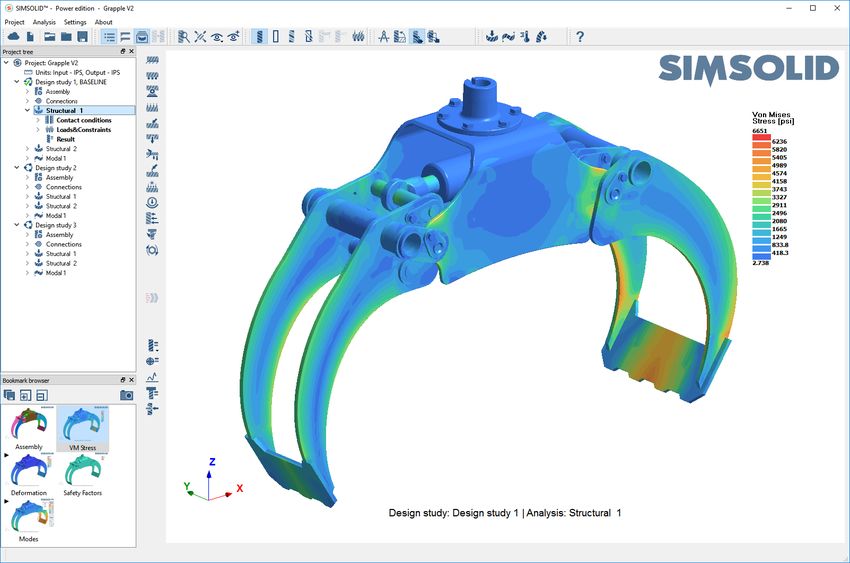
SimSolid FAST START TRAINING
SimSolid technology steps – Solving
Geometry evaluation
• Feature recognition and
Result functions
evaluation
• Create initial equations
Solution pass
• Solve equation set
• Strain/stress recovery
Loop and repeat
based on specified
Error analysis
• Displacement error analysis at constraints
• Traction (force) error analysis at loaded or
# of max passes free surfaces of parts
• Displacement and energy convergence
analysis
Solution adaption
• Adding DOF locally at constraints
• Adding DOF locally in volumes
• Adding special approximation
9 12/2/2018 functions at features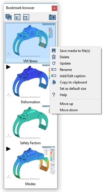
SimSolid FAST START TRAINING
SimSolid technology steps – Results
Create response mesh
• Used to map result functions to design geometry
• Can be redefined on-the-fly
Evaluate quantities of interest to contour plot
• Values determined at the nodes of the response mesh
• Very fast - done on-the-fly, the nodal values are not saved
Display reactions
• At supports
• At connections
• Parts resultants
Fast re-analysis
• SimSolid remembers response mesh Efficient coupled analysis
• Results of one analysis are directly used
and incremental analytic functions in analytical form in other analyses
• Re-analysis typically processes faster • Thermal-stress, nonlinear analysis,
10 12/2/2018 dynamicsSimSolid FAST START TRAINING
SimSolid Do’s and Dont’s
SimSolid’s unique numerical solution methods do not have many of the limitations found in traditional FEA. With SimSolid, there is
no meshing and geometry handling is much easier. Here is a short list of DO’s and DONT’s hints and tips to help get you going.
• Do use the CAD geometry as is – SimSolid is capable of analyzing all geometric detail including fillets, rounds, holes, imprints
and other small features. Even surface construction complexity such as odd face transitions and small splinter surfaces are OK
to leave in unaltered. SimSolid is tolerant of imprecise geometry.
• Don’t merge assemblies – Most traditional FEA applications recommend this step in order to help the meshing process and
eliminate complex and cumbersome specialty element connections. With SimSolid this is never done. Always keep all CAD
parts separate.
• Don’t be afraid of large assemblies – With SimSolid, it is acceptable to leave in small parts such as bolts, nuts and washers.
Even bolts with threads are OK. SimSolid unique adaptive solution process will work efficiently on models with hundreds of
parts.
• Don’t be afraid of imperfect connection geometry – In SimSolid, assembly part connections are very tolerant of gaps
(geometry that does not touch) and penetrations (geometry that overlaps). Its assembly connections are industry best at
handling ragged contact surfaces and setup is fast and easy.
• Do look at our suggested workflows. SimSolid should be used differently than traditional FEA methods. Read here to find out
how.
11 12/2/2018SimSolid FAST START TRAINING
Section 1
MY FIRST ANALYSIS
12SimSolid FAST START TRAINING
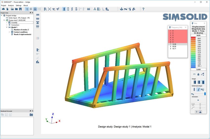
My first analysis
• As an introduction, we will do a quick modal analysis to calculate the first 3 flexible
modes of a 30-part assembly of a bridge
• More explanation coming, but for now this will provide a view of how few inputs
are actually required
• Our 4 steps to accomplish this are:
1. Import STL geometry, create connections
2. Apply material property
3. Create modal analysis & run
4. Examine frequencies and mode shapes
13 12/2/2018SimSolid FAST START TRAINING
4-step analysis – calculate first 3 flexible modes
Import geometry, create connections
Apply material property
Create modal analysis & run
Examine frequencies and mode shapes
Start by picking here
14 12/2/2018SimSolid FAST START TRAINING
4-step analysis – calculate first 3 flexible modes
Import geometry, create connections
Apply material property
Create modal analysis & run
Examine frequencies and mode shapes
Pick material
Select apply
material
Start by picking here
Then apply it to all parts in
assembly and press OK
15 12/2/2018SimSolid FAST START TRAINING
4-step analysis – calculate first 3 flexible modes
Import geometry, create connections
Apply material property
Create modal analysis & run
Examine frequencies and mode shapes
Create new modal analysis Press here to start
from the main window toolbar Ask to find 3 flexible modes modal analysis
Make sure modal
workbench is active
16 12/2/2018SimSolid FAST START TRAINING
4-step analysis – calculate first 3 flexible modes
Import geometry, create
connections
Apply material property
Frequencies
Create modal analysis
& run Pick Displacement
magnitude
Examine frequencies and
mode shapes
Pick “Show deformed shape”
Pick here to animate
mode shape
17 12/2/2018SimSolid FAST START TRAINING
Section 3
USER INTERFACE – BASIC CONCEPTS
18SimSolid FAST START TRAINING
User interface basic concepts
• Screen areas
• Mouse buttons
• Main menu toolbars
• Graphics window
• Project tree
• Workbench toolbars
• Bookmark browser
• Specifying units
19 12/2/2018SimSolid FAST START TRAINING
Main toolbar
Project Tree Workbench
toolbar
Graphics Area
Bookmark Browser
20 12/2/2018SimSolid FAST START TRAINING
Mouse buttons – View manipulation
• Model Rotation – left mouse button (LMB) click
+ drag to rotate model
• Model Translation – right mouse button (RMB)
click + drag to pan model.
• Model Zoom – rotate the mouse wheel to zoom
the model.
• Model Zoom Extents (Fit): either pick the fit to
window button on the main toolbar or click the
window background with RMB and select “Fit
geometry to window”
• Box Zoom – use the "Box zoom" button from
the main window toolbar then click and drag
box using LMB. As faster alternative, just hold
SHIFT key and drag with LMB.
• Alternative CAD system mouse mappings are
available from “Settings>Mouse setting” menu
21 12/2/2018SimSolid FAST START TRAINING
Mouse buttons – Entity selection
• Single select – Select a single entity using the
left mouse button (LMB)
• Multiple select – Select multiple entities by
holding down Ctrl key and select with LMB
• Box select – Holding down Ctrl key and drag to
select items within the box
– Drag box down – any entities partial
enclosed within the box will be selected
– Drag box up – all entities must be fully
enclosed within the box to be selected
22 12/2/2018SimSolid FAST START TRAINING
Standard & custom views
Standard views User defined views
• Standard views – top, bottom, front,
back, etc.
– Available on pulldown menu in Select arrowhead to point
Y axis normal to screen
main toolbar, or
– by selecting main axis X, Y or Z
arrowheads
• Z-up or Y-up definition – defined in
the “Settings>Screen coordinate Select arrowhead to
reverse (Z into screen)
system” menu
• User defined views
– Available on main toolbar button
– Are added to bottom of Standard
views pull down menu
Double click to edit name
– User defined views are model
specific – are saved in Project file
23 12/2/2018SimSolid FAST START TRAINING
Main menu toolbar
Show sectioning
plane
Import Project Box zoom Show parts Show hidden Measurements
from cloud tree on/off on/off shaded parts as ghosts tool
Import Show part Help window
Highlight items Fit geometry Precise Show
from file edges on/off
with comments to window rotation hidden parts
Open, close, Create new analysis –
save project User defined Show parts Box selection static, modal, thermal or
views translucent on/off nonlinear static
Bookmark Standard Show part in Selection
browser on/off views random colors filter
Show boundary
conditions
24 12/2/2018SimSolid FAST START TRAINING
Graphics window
Immovable constraint
on part face
Loaded part
face
Entity context menu – select
part with RMB. CTRL-select to
select multiple parts
25 12/2/2018SimSolid FAST START TRAINING
Project tree SI
TIP: The Project tree is the primary way to Select Assembly to
set workbench focus
manage all SimSolid entity interaction
• The project tree contains multiple workbenches.
• A workbench is a related set of project tree All workbench entities
shown in bold
entities to which certain actions can be applied.
• Entities in the workbench will be bolded when
Workbench toolbar
active and a workbench toolbar will appear to
the right of the project tree.
• Entity selection can be made in project tree or
directly on object in graphics window
– Select using left mouse button (LMB)
– Group select using shift-LMB or Ctrl-LMB
• Display entity context menu using right mouse
button (RMB) selection in either the graphic
window or project tree
• Double-click project tree entity to open Edit
dialogs
26 12/2/2018SimSolid FAST START TRAINING
Workbench toolbars
Assembly toolbar Connections toolbar
Apply material Auto create
property connections
Resume suppressed Manually create
parts connections
Create rigid part Create Spot and Laser Welds
Review Connections
Create spot
Create virtual connectors
Create local
coordinate Show disconnected
system groups of parts
Review and clean
assembly
Check for geometry
defects
NOTE: The toolbar displayed is based on the currently selected
workbench in the project tree
27 12/2/2018SimSolid FAST START TRAINING
Workbench toolbars
Structural analysis toolbar
Immovable
support
Sliding
support
Run the
Hinge support analysis
Check rigid
Spring support motions
Create result
Pressure load contour plot
Result point
Uniform load or
probe
displacement
Gravity load Create XY plot
Inertia load Bolt/nut forces
Spot weld forces –
Remote load Power Edition only
Reaction
Thermal load forces
Bearing load
Hydrostatic load
Bolt tightening
Nut tightening
NOTE: The toolbar displayed is based on the currently selected
28 12/2/2018
workbench in the project treeSimSolid FAST START TRAINING
Bookmark browser
Save images and
• Saves the current graphics state along animations to media
files
Create new
bookmark
RMB select thumbnail to
with any overlaid windows (such as display context menu
summary dialogs)
Increase/decrease
• Great way to document your work thumbnail size
• Bookmarks are saved in the project file Triangle indicates
Update bookmark with contents
of current graphics window
animation bookmark
• Bookmark images and animations can
be exported to media files to use in
reports. Files are saved in .png and Adds onscreen caption. Drag
Double-click caption to reposition in
.mp4 formats name to edit graphics area
To save animation,
create new bookmark Select any thumbnail to
while animation is restore graphics view
active
29 12/2/2018SimSolid FAST START TRAINING
Interface Synchronization
• The project tree,
bookmark browser and Project tree workbench
graphics window states will synchronize as well
are always synchronized
• The focus will be
consistent for all user
interface controls
• Select any one and the
others will update
Graphics area will
synchronize with bookmark
Select bookmark
30 12/2/2018SimSolid FAST START TRAINING
Specifying units
Double-click here to
open units dialog
Set the number format of result
output here – engineering,
scientific or concise mix
Both input and output
units can be set
Check here to make these settings
the default for new projects
TIP: SimSolid manages all units. These are the default values only. They can still be overridden on
most data input forms. Mixed unit input is fully supported throughout the product.
31 12/2/2018SimSolid FAST START TRAINING
Section 4
PROCESSING DESIGN GEOMETRY
32SimSolid FAST START TRAINING
Processing design geometry
• Design Studies
• Geometry import
– from SOLIDWORKS, Autodesk Fusion 360
– from Onshape
– From STL
– From CAD files directly
• Creating connections
• Adjusting visualization styles
• Assigning materials
33 12/2/2018SimSolid FAST START TRAINING
Design studies
• Design Studies allow you to quickly evaluate and BASELINE Study – this is the
SI
source for all material
compare the structural performance from different properties, connections and
geometric configurations. A single SimSolid Project file analysis conditions
can contain multiple Design Studies each with their own
unique set of geometry and analyses.
• Every time geometry is imported, it is placed into a new
design study and SimSolid will attempt to reapply
existing material property, connection and analysis
definition data. The source for this data will be the Each time new geometry
is read in, the data
BASELINE design study. attributes from the
baseline study will be
• The first design study defaults to BASELINE but this can applied here
be changed at any time by selecting the right mouse
button (RMB) menu “Set as baseline” on any design
study root node in the project tree.
34 12/2/2018SimSolid FAST START TRAINING
Design studies - Managing associativity
• Every time geometry is imported, it is placed into a new
design study and SimSolid will attempt to reapply existing
BASELINE material property, connection and analysis
definition data.
• Items that cannot be reapplied will be marked in red
• All red entities must be resolved before a new analysis can
be started
• For contact conditions, SimSolid will bond automatically.
Review to make sure this is what you want. Either, RMB
select then pick “Accept contact condition(s) in red” or
double-click to Edit
• For boundary conditions, double-click and reselect the
location (face, edge, spot, etc.)
35 12/2/2018SimSolid FAST START TRAINING
Geometry considerations
• SimSolid does not import CAD surface or solid geometry. Instead it CAD face structure
uses a more efficient faceted geometric approach.
• From CAD (SOLIDWORKS, Fusion 360 or Onshape)
– Full CAD hierarchical assembly tree structure used
– CAD part faces used (preferred)
– Facets are based on CAD add-in faceting parameters
• From STL
– Multi-body STL used. Flat assembly tree structure only
– SimSolid determined part face structure based on surface curvature (will miss fillet
faces, see example on right)
– Facets are based on STL file export parameters (must take care, as some CAD
system export poor quality STL) STL face structure
No fillet faces
36 12/2/2018SimSolid FAST START TRAINING
Geometry facet settings
• SimSolid does not import CAD surface or solid
geometry. Instead it uses a more efficient
No fillet faces
faceted geometric approach.
• To modify facet parameters select the
Settings → Geometry import settings menu
• 4 levels: standard (default), enhanced, fine,
custom
• Faceting best practice – use a level of
tessellation that is sufficient to capture the
general part shape but not be overly fine. Too
much detail does not improve the solution
accuracy and only slows down the solution
sequence.
37 12/2/2018SimSolid FAST START TRAINING
CAD import vs STL – which is better?
NOTE: The SimSolid generic STL importer is intended for use with more organic geometries (for example 3D lattice type parts) that cannot
be easily represented by standard CAD solids.
We do not recommend STL format for traditional CAD geometry for the following reasons:
• STL does not represent the assembly topology. With CAD geometry integration, you get the full Assembly > sub assembly > part >
part face tree structure. STL is a simple multi-body approach.
• STL does not represent CAD faces. STL does not have a face structure. SimSolid must infer faces from curvature to find edges. This will
lead to a different set of faces with curved geometry (fillets and holes) and can make it more difficult to apply loads and constraints.
• STL can be problematic for curved geometries. The user must take care to adjust facet density to adequately represent curved
geometry.
• STL not as robust with welds. Weld functionality is particularly oriented to CAD representations of geometry (faces and edges). STL
representation does not in general work as well.
• STL is not as efficient. STL are just simple facets. It takes longer to import and validate them. SimSolid must infer solid bodies and
faces. This takes more time and can lead to longer solve times. With CAD solids we fully understand the topology and take advantage
of part instances to represent/solve multiple similar parts more efficiently.
• STL is not as robust/reliable. There are instances where STL geometry is not as robust with non-manifold geometries, etc.
STL will work with generic CAD geometries, but as you can see, the direct CAD integration is far superior, easier to support and is in most
cases the preferred path.
38 12/2/2018SimSolid FAST START TRAINING
Design studies – Copying analyses
• Analyses may be easily copied between
design studies.
• RMB select the analysis and pick “Copy to”
and the location target.
• Power Edition only - static analysis contact
and boundary conditions can be copied to
a new non-linear analysis. RMB select the
analysis and pick “Copy to non-linear
analysis”
– Note: when doing nonlinear analysis, you have the
option to use follower loads. Simply double-click
the load to Edit and select the follower icon next to
the load value.
39 12/2/2018SimSolid FAST START TRAINING
Geometry and material property import from SOLIDWORKS
Pick here to load the current
SOLIDWORKS visible geometry Pick here to save model to SimSolid
into SimSolid – uses shared formatted file – use this method if SimSolid is
memory (preferred method) on a different machine from SOLIDWORKS
Pick here to adjust face
facet settings
Choose which active SimSolid
project to load the design
study geometry into.
Inside of SOLIDWORKS,
make sure SimSolid add-
in is activated
TIP: Install SimSolid on same machine as SOLIDWORKS and
installer will also load SimSolid SOLIDWORKS add-in
40 12/2/2018SimSolid FAST START TRAINING
Geometry & material property import from Fusion 360
Choose which active
Pick here to load the current Fusion 360 SimSolid project to load the
visible (body or mesh body) geometry into design study geometry into.
SimSolid – uses shared memory (preferred
method)
Pick here to save model to SimSolid
formatted file – use this method if SimSolid is
on a different machine from Fusion 360
Pick here to adjust face
facet settings
Inside of Fusion 360, make sure
SimSolid add-in is activated
TIP: Install SimSolid on same machine as Fusion 360 and
41 12/2/2018 installer will also load SimSolid Fusion 360 add-inSimSolid FAST START TRAINING
Geometry import from Onshape Open browser to
Select cloud settings to log into Onshape
authorize Onshape account and authorize
(required one time)
Select here to open
Onshape document. Right
mouse button select here
to change Onshape
workspace.
Select Import
from cloud
Select here to select part
or assembly studio
Select here to import assembly into SimSolid. Or better
42 12/2/2018 yet, just double-click on the Part or Assembly studio icon
and skip the Open button.SimSolid FAST START TRAINING
Geometry import from STL file
• Select the “Import from file” button
from the Main Toolbar. Browse to
where your file (or files) are located, Select Import
from file
select all of them and the press Open.
• SimSolid knows all about units, but
unfortunately STL does not. A dialog
allows you to specify the units that the
file is in. Bounding box dimensions are
displayed to help you decide.
43 12/2/2018SimSolid FAST START TRAINING
Direct geometry import from CAD files
Select Import
from file
Select file format filter
44 12/2/2018SimSolid FAST START TRAINING
Geometry overlap check on model import
• A part overlap check on will be done during Select here to
expand tree branch
model import
• This provides useful feedback on model quality.
• Overlaps are presented as primary parts grouped
with their overlapping neighbors.
• Expand the tree branch to see the neighbor
parts. Select a part name to view in the graphics
area. SHIFT or CTRL select the neighbor parts to
help visualize the overlap. Use zoom to part
button to focus the view only on the selection
• For those that don’t require this function, it can
be deactivated in the Settings>Geometry import
setting menu Activate zoom to
Group select all
overlapping parts
selection here
NOTE: In SimSolid, parts that overlap can still be connected. A best practice
it to make sure this overlap is not in a critical stress region of the model.
45 12/2/2018SimSolid FAST START TRAINING
Automatically Create Connections
• Once the geometry is read in, SimSolid will display a dialog to
prompt for connection tolerances. The “Automatic connections”
operation tries to create connections between all parts using these
tolerances as a guide.
• Once complete, you will see a list of all parts and connections in the
Project tree.
• If there are parts that SimSolid cannot connect, a dialog will be
displayed to notify you and give you the option to suppress or
delete the unconnected entities.
• Connections can be created manually as well – see icons in the
connections workbench toolbar
Auto create
connections
Manually create
connections
Show disconnected
groups of parts
NOTE: A best practice it to make the gap and penetration tolerance as
small as possible. Values that are too big can over constrain the model.
46 12/2/2018SimSolid FAST START TRAINING
Review Part Connections
• METHOD 1
– To see where a connection is on the model, simple select
it in the project tree. The model turns transparent and
the connection is highlighted by a red cross-hatch
pattern.
– For instances where the model is more complex, use the
“Zoom In” command on the Context menu (use RMB to
select the connection). Now the view will zoom in to the
connection location and only the two parts associated
with the connection are displayed. A “+”and “–“ Zoom
button will appear on the connection to allow you to fine
tune the view.
• METHOD 2
– An alternate method is to RMB pick a part and select the
“Review part connections” menu item. This display a
dialog listing all connections associated with the selected
part only.
47 12/2/2018SimSolid FAST START TRAINING
Review Part Connections
• METHOD 3
– Use Review connections dialog.
– Allows you to sort all connections by attribute.
Just pick the column headers
– Any connection selected will be highlighted in
the graphics window
48 12/2/2018SimSolid FAST START TRAINING
Adjusting visualization styles
• Parts can be displayed as shaded, wireframe or transparent
• Parts can be hidden Show parts
shaded
Show hidden
parts as ghosts
• Hidden parts can be shown as ghosted (light transparent) Show part Show
edges hidden parts
• To hide part:
– select one or more parts in either the project tree or graphics
region. Use CTRL key to multi-select
– RMB select “Hide menu”
• To show hidden parts, RMB in a blank area of the graphics Show parts
translucent
window and select “show all hidden parts”
Show part in Show boundary
random colors conditions
TIP: Use bookmarks to save a favorite graphics style or visual grouping
49 12/2/2018SimSolid FAST START TRAINING
Visualization Examples
Random colored parts Translucent parts Results plot with hidden parts shown
as ghosted
Edge only display Hidden parts shown as ghosted (light Edges on (undeformed), deformed
transparent) shape with continuous contour plot
50 12/2/2018SimSolid FAST START TRAINING
Assign Material Properties
NOTE: CAD materials will be imported
Select Select Assign
with model geometry, if defined.
Assembly material
Select
material
Material name listed
next to parts
Select here and OK to assign selected material to
Select here and OK to assign
selected parts. Parts can be selected in either
selected material to all parts
the project tree or the graphics window.
51 12/2/2018SimSolid FAST START TRAINING
Using default materials
If you change your mind and find you
no longer want a default material,
Pick material RMB select and pick “Clear”
SI SI
Double-click here to
open materials dialog
NOTE: Default materials will be
applied to any parts without
material when an analysis is run.
TIP: This only needs to be set up
one time. Will be saved as a user
preference.
Pick OK
52 12/2/2018SimSolid FAST START TRAINING
Review material property assignment
• Large assemblies can have many material
properties. SimSolid makes it easy to SI
review material property assignments.
• RMB pick Assembly and select:
– Show>Materials – This will show a list of
all material property assignments. Pick a
material name and all parts with that
material property will be highlighted.
– Show>Parts without materials – This will
hide all part with materials and only show
parts without material property
assignments.
53 12/2/2018SimSolid FAST START TRAINING
Hide parts of different material
• Quick method to focus display on parts
with identical material properties SI
• Useful when displaying result contours
• Accessed by a right mouse button select
on a part in the project tree or in the
graphics region
54 12/2/2018SimSolid FAST START TRAINING
Suppressing and deleting parts
• Suppressing parts removes them from
inclusion in related analyses but leaves
them in the Project file
• Deleting parts removes them from the
project file. Use caution as delete cannot
be undone.
• Parts may be suppressed or deleted from
current or all design studies
• Parts are suppressed or deleted using
right mouse button (RMB) selection of a
group of parts in either the project tree
or the graphics window.
• Suppressed parts are shown in the
project tree as crossed out and grey
• Use RMB menu “Resume” to unsuppress
a part and reactivate it.
55 12/2/2018SimSolid FAST START TRAINING
Section 5
CREATING AN ANALYSIS
56SimSolid FAST START TRAINING
Creating an analysis
• Create new analysis
• Specify contact conditions
• Create boundary conditions
• Specify solution settings
• Run the analysis
• Consider non-linear effects
57 12/2/2018SimSolid FAST START TRAINING
Create new analysis
Create a new analysis by selecting from either the Analysis menu or main toolbar.
58 12/2/2018SimSolid FAST START TRAINING
Specify contact conditions
• SimSolid contact conditions can be bonding, sliding,
separating* or disabled
• Contact conditions are created automatically but can
be changed by user
• RMB pick a connection then select Edit
*NOTE: Separating contact is a non-linear effect and must
first be activated in the Structural settings dialog
59 12/2/2018SimSolid FAST START TRAINING
Create boundary conditions
Select analysis
workbench
Select where
to apply to
Select
boundary
condition
(optional) select units for this
boundary condition
Toggle between load and
specified displacement
Enter load or
displacement value
60 12/2/2018SimSolid FAST START TRAINING
Other boundary conditions
Structural/modal analysis toolbars Thermal analysis toolbar
Immovable
support
Sliding Temperature
support
Flux
Hinge support
Spring support Convection
Volumetric heat
Pressure load
Uniform load or
displacement
Gravity load
Inertia load
Remote load
Thermal load
Bearing load
Hydrostatic load
Bolt tightening
Nut tightening
61 12/2/2018Select Spot type –
SimSolid FAST START TRAINING Select Spot as rectangle, circle, triangle
location
Using Spots
• Many traditional FEA systems require
faces to be split to create localized
loads and constraints Select existing or pick
here to create new spot Define shape
• SimSolid has a better way – Spots attributes
• Spots can be rectangular, circular or
triangular. They can even be points,
lines or arcs
• Spots are projected onto parts normal
to the screen
• Pick part face to orient part and If necessary, fine
tune location
Pick OK to
project onto
center view part(s)
• Spots can be projected onto more
than one face or more than one part Specify what to
project Spot onto
Pick on part to position Spot
62 12/2/2018SimSolid FAST START TRAINING
Pick here to adjust the max
Specify solution settings number of solution passes
Access here by double-click
or RMB and Edit
SimSolid employs a proprietary adaptive technology to automatically
refine the solution in the areas where it is necessary to achieve the
highest accuracy. Multiple solution passes are performed and with each
pass, accuracy measures are created and equations are enriched locally as
required. All that needs to be specified by the user are the maximum
number of solution passes along with a small set of optional settings.
TIP: Solution settings can be applied globally to
the entire model or locally to a group of parts.
63 12/2/2018SimSolid FAST START TRAINING
Individual settings controls
• Adapt to features – Uses special logic that has more aggressive adaptivity for stress
gradient areas at local features. Applies only to structural linear and nonlinear
statics. This is not used in modal or thermal analyses.
• Adapt to thin solids – provides special functions for a more accurate representation
in thin curved solid sections. A best practice is to use this locally on a part by part
basis.
• Refinement level – increases the refinement level locally for a group of parts. Three
levels are possible – standard, increased and high. Please see special note about
part scale for this refinement setting
64 12/2/2018SimSolid FAST START TRAINING
Local solution settings
STEPS
1. Create a part group by selecting the New button in the
dialog.
2. Select one or more parts from either the graphics window or
project tree to add them to the group
3. Specify any desired local settings and pick the Apply button.
ADDITIONAL NOTES
1. When a group name is selected on the dialog the current
group settings will be shown and the parts that belong to Pick here to create
that group will be highlighted in the graphics window. new group
2. The Group label indicates the number of parts in the group
and the relative volume of the group as compared to the
entire assembly. Use the relative volume as a guide when
selected local refinement settings. Pick Apply to
3. To remove a single part group, select the group and then update the group
pick the Delete button. To remove all local group definitions
refinements, select the Reset all button. To re-set factory
solution settings pick Factory reset button.
65 12/2/2018SimSolid FAST START TRAINING
Default solution settings
Set the max number of passes
Access from the and the setting options
settings menu
These are the solution settings that are used by default on a new project
66 12/2/2018SimSolid FAST START TRAINING
Special note about part scale
• Solution settings define a strategy of solution adaptation and are applied at the scale of the selected part group.
• Global solution settings define the solution refinement strategy on the whole assembly assuming that accuracy
requirements are approximately equal on all parts. With global solution settings, the scale is the size of the whole
assembly.
• Local solutions setting define the solution refinement strategy on a part or group of parts. The scale of the settings
is the size of the parts in the group.
• Therefore, the same solution settings applied to the whole assembly or to a specific part will have different effects
on the accuracy. The local settings are always more aggressive on the given set of parts because the scale is
smaller.
• This facilitates the ability to do Global-local analysis and to focus the adaptive refinement on particular areas of
interest.
TIP: To use the most detailed solution scale, create a part group containing a single part.
67 12/2/2018SimSolid FAST START TRAINING
Solution settings – workflow roadmap
The recommended way to use Solution settings is as follows:
1. To find the overall system load path: use the default Global solution settings
2. Considerations for overall stress studies: To refine stresses over the entire model,
select the “Adapt to features” checkbox solution setting and rerun the model.
3. To examine overall solution convergence: To examine solution convergence over
the entire model, increase the number of adaptive passes and rerun the model.
Number of passes can be set between 3 and 9, but this value is rarely set above 6.
4. Considerations for local stress studies: Use local part groups. Remember, part
group settings are done at the part group local scale.
5. Considerations for thin curved solids: For parts that are thin and curved, the Adapt
to thin solids checkbox should be activated. This is best done on a part by part basis
using local part groups.
68 12/2/2018SimSolid FAST START TRAINING
Run the analysis
Pick analysis
workbench
When done, pick
here to display
analysis summary
Pick here
to run
69 12/2/2018SimSolid FAST START TRAINING
Non-linear option – separating contact
• Non-linear structural Activate
effects are specified in
Structural settings dialog.
• Separating contact allows Bonded Contact
parts to partially or
completely separate from
each other under load.
• Separating contact
Define
conditions are defined in
the contact conditions
branch of the project tree
Separating Contact
70 12/2/2018SimSolid FAST START TRAINING
Non-linear option – Material
• Non-linear structural effects are Activate
specified in Structural settings dialog.
• Material non-linear is elastic-plastic
• At least one model material property
must contain a non-linear stress vs
strain curve.
• For any analysis that exceed the
elastic limit, SimSolid will provide
three outputs for each result
quantity:
– elasto-plastic, full load, these
are the results at full load
assuming a nonlinear stress-
strain curve is used;
– elastic, full load, these are the Select NL
Material
results at full load assuming a
linear (straight) stress-strain
curve is used, and;
– after unloading, these are the
residual results after loading
has been removed Stress vs strain curve
71 12/2/2018 NOTE: Non-linear is not available in SimSolid Standard editionSimSolid FAST START TRAINING
Non-linear option – Geometric
Activate
• Non-linear structural effects are
specified in Structural settings
dialog.
• In geometric non-linear analysis,
changes in geometry as the
structure deforms are taken into
account when iteratively solving
the strain-displacement and
equilibrium equations.
• Will calculate large displacement Select here to
activate follower load
and rotations but assumes small
strains (linear elastic)
• Follower loads can be optionally
defined.
• Typical applications include
slender structures, sheet metal
and stability analysis of all types.
72 12/2/2018SimSolid FAST START TRAINING
Section 6
INTERPRETING RESULTS
73SimSolid FAST START TRAINING
Interpreting results
• Creating a contour plot
• Fast results switching
• Other display results
– Safety factor plots
– XY plots
– Point probes
– Reaction forces
– Spot weld forces
74 12/2/2018SimSolid FAST START TRAINING
Creating a contour plot
Pick and hold
• Once the analysis is complete, a Result with LMB
entity icon will appear in the Project
Tree and the Result Plot button will no
longer be greyed out.
• To create a contour plot, click and hold
with the left mouse button (LMB) on
the Result Plot button, then select the
desired result type from the pop-up Pick type of contour
menu. to display
75 12/2/2018SimSolid FAST START TRAINING
Contour legend controls Select Value to
Set Upper
Contour Bound
• Contour legend controls are on plot dialog
• Parts can be hidden during results display. Just RMB select on the
model or in the Project tree and pick Hide. Hold down the CTRL
key to select more than one part.
• Contour can be on deformed or undeformed part geometry Lock
Max Min
• Pick “Show part edges” button in main window toolbar to display Bounds Select Value to
Set Lower
undeformed edges Contour Bound
Set
• Max/Min labels can be displayed on model. Drag to reposition. Output Show Min/Max
Units Labels
• Legend controls can be hidden and legend can be dragged to any
Show
place in graphics window. Click on legend to bring back controls Deformed
Set Contour Colors
• Max/Min legend bounds can be locked during “Fast results Shape
8, 16 or Continuous
switching” see next slide. NOTE: this lock only works when switch Show
between identical results. Undeformed Set Max
Shape Deform Scale
TIP: Use bookmarks to save a contour plot settings, Current
Start/Stop Animation
including animations Animation Frame
Animation Speed
Animation
Steps
76 12/2/2018 Hide legend
controlsSimSolid FAST START TRAINING
Fast results switching
While contour is displayed, pick
another analysis. Contour will
“fast results switch” to new data
While contour is displayed, pick
new result entity. Contour will
“fast results switch” to new data
77 12/2/2018SimSolid FAST START TRAINING
Display results - Safety factor plot
Pick and hold
with LMB 2. Pick Material name. Safety factor contour
will be shown for all parts with this material.
Others will be ghost hidden (transparent).
3. Pick number to edit
contour band value then
enter to adjust
1. Pick Safety Factor
3. Or, use sliders to dynamically
adjust contour bands
HINT: CTRL-Select multiple material names to show
78 12/2/2018 safety factors on more than one material group of parts.SimSolid FAST START TRAINING
Display results - XY plot
• While a contour plot is active, use the Graph button in
the Workbench Toolbar to display the XY Graph dialog.
• Simply pick two or more points on the model to get an
XY plot of the result.
• Drag on the plot to pan or use the mouse wheel to
zoom.
• The Refit button get you back to the original plot scales.
• Use “Save As” to save the plot in a variety of graphic or
text formats.
79 12/2/2018SimSolid FAST START TRAINING
Display results - Point probe tool
• While a contour plot is active,
use the Pick Info button in the
Workbench Toolbar to display the
point probe tool.
• Simply pick one or more points
on the model to get numeric
values at those locations.
80 12/2/2018SimSolid FAST START TRAINING
Reaction forces
• SimSolid provides an extensive set of Reaction
forces including:
– Boundary supports
– Connections
– Parts
– Spot welds
81 12/2/2018SimSolid FAST START TRAINING
Display results - Support forces
Pick a boundary support
(use CTRL to select multiple)
• Pick the “Reaction force” button in the Workbench
toolbar to display the Reaction Force dialog.
• Select any boundary support to get the reaction
forces summary.
Reaction force and moment
Pick here to open vectors shown at centroid
Reaction force dialog of support area. Parts with
supports highlighted in blue
82 12/2/2018SimSolid FAST START TRAINING
Display results - Connection forces
• Pick the “Connections” tab in the reaction
forces dialog
• Resultant force and moment for the
selected connection is given along with the
location of the force centroid.
• Only one connection can be selected at a
time.
• Force and moment vectors are displayed in
the geometry window.
• Connecting parts are blue and red. Vectors
are oriented with respect to the blue part.
• Use the zoom in (“plus”) button to zoom to
the local area of interest.
83 12/2/2018SimSolid FAST START TRAINING
Display results - Part forces
• Total contact force and moments are Part with no applied loads.
Forces sum to zero
displayed for one or more selected set of
parts.
• Pick a part to add it to the list. The selected
part will display a summary of all connection
and support forces excluding applied loads
(including body loads such as gravity).
• Some typical examples of use include:
– Connections only. No applied loads. Part force will sum
to zero.
– Connections with applied loads. Part force will sum to
applied loads.
– Connections only. No applied loads with the exception
that gravity is active. Part force will equal part weight.
• In addition, individual group of part Single part connection
connections can be examined. Select the forces and moments
expand icon to the left of the part name to
show the part connections. Select one or
more connections to sum forces on the group
as shown (example on right).
84 12/2/2018SimSolid FAST START TRAINING
Display results – Spot weld forces
Pick column name
to sort list
Pick single Spot weld to
view resultant force
vector on the model
Or, CTRL-Select and SHIFT-Select
multiple values to sum forces
Pick here to open Spot
weld forces dialog –
Power edition only
85 12/2/2018SimSolid FAST START TRAINING
Refine results plot on a face
• A right mouse button (RMB) option is available to
locally refine result contours on a single part face.
• This can be useful for long narrow regions that
may not have enough plotting resolution.
• Note that this does not affect the accuracy of the
results. It only provides more sampling points to
map results to.
• May be applied more than once to some faces.
There is an upper limit on the resolution that is
allowed. Once reached, this command will notify
the user that no more refinement on the face is
possible.
• Use with caution. Once additional points are
mapped, you cannot go back to the original
plotting resolution.
86 12/2/2018SimSolid FAST START TRAINING
Section 7
TYPICAL SIMSOLID WORKFLOWS
87SimSolid FAST START TRAINING
Typical Workflows
• SimSolid workflows are meant to be used from an assembly down to a part. This is
opposite from typical FEA that starts from simple parts/shapes. This eliminates the
assumptions that designers must make for geometry simplification and part load
magnitude/direction in typical FEA.
• The SimSolid analysis approach is to first determine load paths from the full
assembly and then drill in to single parts and hot spots details.
• Typical SimSolid 2 stage workflow
1. Assembly load path prediction
2. Detailed stress study
88 12/2/2018SimSolid FAST START TRAINING
STEP 1 - Load path prediction workflow
• Goal: capture overall load path and reaction forces
• Inputs:
– Geometry – full assembly geometry with bonded connections
– BC’s – simple overall supports and active loads. Don’t forget gravity.
– Solution settings – standard default settings. May want to run second
analysis with 4 solution passes to examine load path convergence
• Outputs to look at:
– Displacements
– Reaction forces
– General overall stress distribution
89 12/2/2018SimSolid FAST START TRAINING
STEP 2 - Detailed stress prediction workflow
• Goal: capture detailed displacement and stress
• Inputs: Increase # solution
passes to 4, 5 or 6
– Connections – add more detail to connections in local
areas of interest.
• Is connection density OK. If connection area is small or thin, Create local group
or parts to focus on
may consider increasing connection resolution
• Is sliding or separating contact more appropriate? Separating
contact is OK due to low computation overhead. Go ahead
and use it. In local part group adjust
– Solution settings settings for more detail
• Use additional passes – 4, 5 or 6
• Use local groups to focus adaption on local hot spots
• Outputs to look at:
– Impact of separating/sliding connections on overall
deformations
– Local stresses
– Connection and part forces
90 12/2/2018SimSolid FAST START TRAINING
Section 8
ADDITIONAL TOPICS AND SOURCES FOR
MORE INFORMATION
91SimSolid FAST START TRAINING
Additional topics - Not covered here
• Thermal & thermal stress analyses • Modal participation factors
• Geometric nonlinear analysis • Personalize the user interface
• Material nonlinear analysis • Virtual connectors
• Bolted connections • Creating custom materials
• Specified displacement in local coordinate • Importing materials from .csv files
systems • Measuring distance and gaps
• Rigid parts • Adding/editing/viewing project tree
• Standard and user defined views comments
• Hydrostatic loads • Creating a MS PowerPoint report
• Inertia loads • Spot and laser welds
• Bearing loads and hinge constraint • Fillet/seam welds
• Exporting animations
92 12/2/2018SimSolid FAST START TRAINING
Next Steps
Go ahead and try SimSolid for yourself.
• Compare it with an analysis done using traditional FEA methods. But when using
SimSolid, use the full CAD geometry and not the geometry that has been simplified
for FEA.
• Next, try it on an large assembly. Remember, never merge parts. Just leave them in
their original design state and use SimSolid connections.
• Then, modify the geometry and reimport it to create a 2nd design study. See how
fast and easy it is to evaluate change on actual CAD designs.
93 12/2/2018You can also read