Further modeling of q 95 windows for the suppression of edge localized modes by resonant magnetic perturbations in the DIII- D tokamak
←
→
Page content transcription
If your browser does not render page correctly, please read the page content below
Further modeling of q95 windows for the
suppression of edge localized modes by
resonant magnetic perturbations in the DIII-
D tokamak
Cite as: Phys. Plasmas 28, 022503 (2021); https://doi.org/10.1063/5.0035874
Submitted: 31 October 2020 . Accepted: 12 January 2021 . Published Online: 02 February 2021

  R. Fitzpatrick

COLLECTIONS

    This paper was selected as an Editor’s Pick

ARTICLES YOU MAY BE INTERESTED IN

Predicting nonresonant pressure-driven MHD modes in equilibria with low magnetic shear
Physics of Plasmas 28, 012106 (2021); https://doi.org/10.1063/5.0032489

First observation of increased DT yield over prediction due to addition of hydrogen
Physics of Plasmas 28, 012707 (2021); https://doi.org/10.1063/5.0030852

Evidence of E × B staircase in HL-2A L-mode tokamak discharges
Physics of Plasmas 28, 012512 (2021); https://doi.org/10.1063/5.0022679

Phys. Plasmas 28, 022503 (2021); https://doi.org/10.1063/5.0035874                            28, 022503

© 2021 Author(s).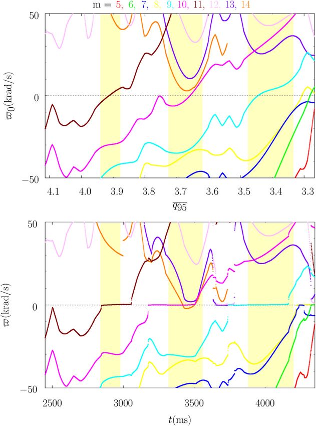
Physics of Plasmas                                                                               ARTICLE           scitation.org/journal/php

    Further modeling of q95 windows for the
    suppression of edge localized modes by resonant
    magnetic perturbations in the DIII-D tokamak
    Cite as: Phys. Plasmas 28, 022503 (2021); doi: 10.1063/5.0035874
    Submitted: 31 October 2020 . Accepted: 12 January 2021 .
    Published Online: 2 February 2021

    R. Fitzpatricka)

    AFFILIATIONS
    Department of Physics, Institute for Fusion Studies, University of Texas at Austin, Austin, Texas 78712, USA

    a)
         Author to whom correspondence should be addressed: rfitzp@farside.ph.utexas.edu

    ABSTRACT
    An improved resonant plasma response model that more accurately captures the physics of the interaction between a tokamak plasma and a
    resonant magnetic perturbation (RMP) is developed. The model interpolates between the linear and the nonlinear response regimes and
    takes into account the fact that the slip-frequency is non-zero in the nonlinear regime. The improved model is incorporated into the extended
    perturbed equilibrium code (EPEC) toroidal asymptotic matching code. The modified EPEC code is used to investigate RMP-induced edge-
    localized-mode (ELM) suppression in DIII-D H-mode discharge #145380. Somewhat surprisingly, allowing for a finite slip-frequency (i.e.,
    relaxing the so-called no-slip constraint) is found to only slightly facilitate the locking of driven magnetic island chains to the RMP, and,
    hence, to only slightly facilitate RMP-induced ELM suppression. This is true despite the fact that the nature of non-locked island solutions is
    radically different when the no-slip constraint is imposed compared to when it is relaxed (in the first case, the widths of the island chains
    driven at the rational surfaces pulsate, and in the second case, they remain steady). The previously obtained conclusion that the response of a
    typical H-mode tokamak plasma to an RMP cannot be accurately modeled by linear theory is confirmed. The previously obtained conclusion
    that the best agreement between theory and observations is achieved by assuming that the natural frequencies of tearing modes, in the
    absence of the RMP, are determined by the local equilibrium E  B velocity is also confirmed.
    Published under license by AIP Publishing. https://doi.org/10.1063/5.0035874

    I. INTRODUCTION                                                             narrow (in the radial direction) regions in which the applied perturba-
          In the context of tokamak plasmas, a resonant magnetic pertur-        tion resonates with the equilibrium magnetic field. Magnetic reconnec-
    bation (RMP) refers to an externally generated, (usually) static, helical   tion can take place within the resonant regions to produce relatively
    magnetic perturbation that resonates at one or more “rational” mag-         narrow magnetic island chains. Within the resonant regions, the
    netic flux-surfaces within the plasma. Resonant magnetic perturba-           plasma response is governed by linear or nonlinear two-fluid resistive-
    tions have been successfully employed to compensate error fields (i.e.,      MHD, depending on whether the induced magnetic island widths are
    accidentally produced RMPs) and, thereby, to prevent the associated         smaller or larger, respectively, than the corresponding linear layer
    formation of locked modes, in a wide variety of different types of toka-    widths. Thus, when employing the asymptotic matching approach, the
    mak discharge.1–3 RMPs have also been successfully used to either mit-      equations of marginally stable ideal-MHD are solved in the so-called
    igate or completely suppress edge-localized-modes (ELMs) in H-mode          “outer region” that comprises most of the plasma (and the surround-
    tokamak discharges.4–9                                                      ing vacuum), the equations of linear/nonlinear two-fluid resistive-
          “Asymptotic matching” is by far the most efficient method for          MHD are solved in the various resonant layers that constitute the
    modeling the response of a tokamak plasma to an RMP.10–20                   so-called “inner region,” and the two sets of solutions are then asymp-
    According to the asymptotic matching approach, the response of the          totically matched to one another.
    plasma to the applied RMP is governed by a combination of flux-                    In the nonlinear resonant response regime, the evolution of the
    freezing and perturbed force balance—this combination is usually            island chain width in a given resonant layer is governed by the familiar
    referred to as “marginally stable ideal-magnetohydrodynamics                “Rutherford island width evolution equation.”12,21 On the other hand,
    (MHD)”—everywhere in the plasma apart from a number of relatively           the phase evolution of the island chain is conventionally governed by

Phys. Plasmas 28, 022503 (2021); doi: 10.1063/5.0035874                                                                                       28, 022503-1
Published under license by AIP Publishing
Physics of Plasmas                                                                                 ARTICLE             scitation.org/journal/php

    the well-known “no-slip constraint.”15 According to this constraint,                                                                      ^ tÞ at radius
                                                                                 flux,” Ws ðtÞ ¼ jWs j eius , which is the actual value of wðr;
    plasma is trapped inside the magnetic separatrix of the island chain,        rs. Here, us is the helical phase of the reconnected magnetic flux.
    which forces the chain to co-rotate with the local plasma flow. In real-            The intrinsic stability of the m, n tearing mode is governed by the
    ity, however, the plasma is able to diffuse resistively across the separa-   dimensionless parameter Ess ¼ ½dw     ^ =d ln rrsþ , where w^ ðrÞ is a solu-
                                                                                                                        s         rs          s
    trix to some extent.22,23                                                    tion of the marginally stable, ideal-MHD equations, for the case of an
          The recently developed, toroidal, asymptotic matching code             m, n helical perturbation, which satisfies physical boundary conditions
    EPEC (extended perturbed equilibrium code) has been used to simu-            at r ¼ 0 and r ¼ a, in the absence of the RMP, and is such that
    late RMP-induced ELM suppression in DIII-D H-mode plasmas.24,25              ^ ðrs Þ ¼ 1.10,16 According to resistive-MHD theory,10,12 if Ess > 0,
                                                                                 w  s
    The original EPEC model incorporates the no-slip constraint. The first        then the m, n tearing mode spontaneously reconnects magnetic flux at
    aim of this paper is to investigate whether improving the resonant           the rational surface to form a helical magnetic island chain. In this
    response component of the EPEC model by relaxing the no-slip con-            paper, it is assumed that Ess < 0 so that the m, n tearing mode is
    straint leads to better agreement with experimental results. The second      intrinsically stable. In this case, any magnetic reconnection that takes
    aim is to examine whether improving the manner in which the reso-            place at the rational surface is due solely to the action of the RMP.
    nant plasma response component of the EPEC model interpolates                      The ideal-MHD response of the plasma to the RMP is governed
    between the linear and the nonlinear regimes gives rise to better agree-     by the dimensionless parameter Esv ¼ ½d w    ^ =d ln rrsþ , where w ^ ðrÞ is
                                                                                                                                 v        rs          v
    ment with experimental results.                                              a solution of the marginally stable, ideal-MHD equations, for the case
                                                                                 of an m, n helical perturbation, which satisfies physical boundary con-
    II. CYLINDRICAL RESONANT RESPONSE MODEL                                      ditions at r ¼ 0 and r ¼ a, in the presence of the RMP, and is such that
    A. Introduction                                                              ^ ðrs Þ ¼ 0.16
                                                                                 w  v
         For the sake of simplicity, and also to make a better connection
    with previous research, let us commence our investigation by discus-         D. Linear response regime
    sing the resonant response of a tokamak plasma to an RMP in cylin-                In the linear response regime, the reconnected magnetic flux
    drical geometry.                                                             induced by the RMP at the rational surface is governed by15,26,27

    B. Plasma equilibrium                                                                      ds       d
                                                                                                   sR     þ i xs Ws ¼ Ess Ws þ Esv Wv ;            (1)
                                                                                                rs     dt
         Consider a large aspect-ratio, low-b, circular cross section, toka-
    mak plasma. Such a plasma is well approximated as a periodic cylin-          where ds is the linear layer width, sR ¼ l0 rs2 rðrs Þ the resistive diffu-
    der. Suppose that the minor radius of the plasma is a. Standard              sion timescale, and
    cylindrical coordinates (r, h, z) are adopted. The system is assumed to
                                                                                                    xs ðtÞ ¼ m Xh ðrs ; tÞ  n X/ ðrs ; tÞ:               (2)
    be periodic in the z-direction, with periodicity length 2p R0 , where
    R0  a is the simulated plasma major radius. It is convenient to             Here, rðrÞ; Xh ðr; tÞ, and X/ ðr; tÞ are the plasma electrical conductiv-
    define the simulated toroidal angle / ¼ z=R0 . The equilibrium mag-           ity, poloidal angular velocity, and toroidal angular velocity profiles,
    netic field is written B ¼ ½0; Bh ðrÞ; B/ . The so-called “safety-factor,”   respectively. Note that, in this paper, we are assuming that the con-
    qðrÞ ¼ r B/ =ðR0 Bh Þ, parameterizes the helical pitches of equilibrium      stant-w approximation10 holds at the rational surface. (It is demon-
    magnetic field-lines.                                                         strated in Ref. 28 that the appropriate linear response regime for an
                                                                                 RMP resonant in the pedestal of a typical DIII-D H-mode discharge is
    C. Plasma response to RMP                                                    the so-called “first semi-collisional regime,” which is indeed a con-
                                                                                 stant-w response regime. Moreover, if the appropriate linear response
          Consider the response of the plasma to an externally generated,
                                                                                 regime is constant-w then so is the appropriate nonlinear response
    static, helical, RMP. Suppose that the RMP has m periods in the poloi-
                                                                                 regime, because the constant-w constraint is easier to satisfy in the
    dal direction and n periods in the toroidal direction. It is convenient to
                                                                                 nonlinear regime than in the linear regime.26,29)
    express the perturbed magnetic field and the perturbed plasma current
                                                                                       Equation (1) can be rewritten as an “amplitude evolution
    density in terms of a perturbed poloidal magnetic flux (divided by
                                                                                 equation,”
    2p R0 ), wðr; h; /; tÞ. In fact, dB ¼ rw  rz, where wðr; h; /; tÞ
        ^ tÞ exp ½i ðm h  n /Þ, and w
    ¼ wðr;                                ^ is real. This particular represen-              ds    djWs j
    tation is valid provided that m=n  a=R0 .15                                               sR        ¼ Ess jWs j þ Esv jWv j cos ðus  uv Þ;          (3)
                                                                                            rs      dt
          The response of the plasma to the RMP is governed by the equa-
    tions of marginally stable, ideal-MHD everywhere in the plasma, apart        combined with a “phase evolution equation,”
    from a relatively narrow (in r) region in the vicinity of the so-called                      dus        Esv rs jWv j
    “rational surface,” minor radius rs, at which qðrs Þ ¼ m=n.15                                    ¼ xs               sin ðus  uv Þ:                  (4)
                                                                                                  dt        sR ds jWs j
          It is convenient to parameterize the RMP in terms of the so-
    called “vacuum magnetic flux,” Wv ðtÞ ¼ jWv j eiuv , which is defined         The final term on the right-hand side of Eq. (4) is termed the “slip-
                        ^ tÞ at radius rs in the presence of the RMP, but
    to be the value of wðr;                                                      frequency” and is the difference between the helical phase velocity of
    in the absence of plasma. Here, uv is the helical phase of the RMP.          the reconnected magnetic flux and that expected on the assumption
    Likewise, the response of the plasma in the vicinity of the rational sur-    that the flux is convected by the plasma flow at the rational surface
    face is parameterized in terms of the so-called “reconnected magnetic        (i.e., dus =dt ¼ xs ). In general, the slip-frequency is non-zero because

Phys. Plasmas 28, 022503 (2021); doi: 10.1063/5.0035874                                                                                            28, 022503-2
Published under license by AIP Publishing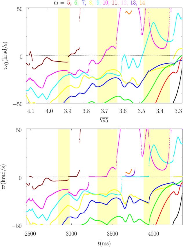
Physics of Plasmas ARTICLE scitation.org/journal/php
the plasma in the vicinity of the rational surface is capable of diffusing pffiffiffiffiffiffiffiffiffiffiffiffiffiffiffiffiffi!1=2
Xs2 þ Ys2
resistively through the linear layer structure. Ws ¼ 4 rs : (11)
ss rs Bh ðrs Þ
E. Nonlinear response regime With the benefit of hindsight, Eqs. (9) and (10) could have been
In the nonlinear response regime, Eq. (3) generalizes to the derived more directly from the following heuristic generalization of
“Rutherford island width evolution equation”:12,21 Eq. (1):23
ðI =2Þ Ws djWs j ðI =2Þ Ws þ ds d
sR ¼ Ess jWs j þ Esv jWv j cos ðus uv Þ; (5) sR þ i xs Ws ¼ Ess Ws þ Esv Wv : (12)
rs dt rs dt
where As seems reasonable, the interpolation weights between the linear
term ds and the nonlinear term ðI =2Þ Ws in the previous equation
1=2
jWs j have both been chosen to be unity, which ensures that the resonant
Ws ¼ 4 rs (6) response model asymptotes to standard constant-w linear layer theory
rs sðrs Þ Bh ðrs Þ
in the limit Ws ds , and to the Rutherford island width evolution
is the full radial width of the magnetic island chain, I ¼ 0:8227, and equation combined with a nonlinear finite slip-frequency model in the
sðrÞ ¼ d ln q=d ln r. The nonlinear regime holds when Ws ds , limit Ws ds .
whereas the linear regime holds when Ws ds .
Equation (5) is usually coupled with the so-called “no-slip III. EPEC MODEL
constraint”15 A. Introduction
dus Let us now generalize our investigation to toroidal geometry.
¼ xs : (7)
dt
B. Modified toroidal resonant response model
The reasoning behind the imposition of this constraint is that plasma
The toroidal model of the response of a tokamak plasma to a
is trapped inside the magnetic separatrix of the island chain that forms
static, externally generated, RMP that is implemented in the EPEC
in the vicinity of the rational surface, which forces the chain to co-
code25 is described in detail in Ref. 24. In the light of the composite
rotate with the local plasma flow. However, in reality, the plasma is
cylindrical resonant response model developed in Sec. II, we propose
able to diffuse resistively across the separatrix to some extent. Hence, to modify the resonant response component of the EPEC model (this
by analogy with Eqs. (3)–(5), and in accordance with Refs. 22 and 23, component is described in Sec. D of Ref. 24).
in this paper we shall modify Eq. (7) such that Equations (D1) and (D2) in Ref. 24 are modified such that
dus Esv rs jWv j ^ X
dt
¼ xs
sR ðI =2Þ Ws jWs j
sin ðus uv Þ: (8) ^ k þ ^d k S k dW k ¼
W ^ k0 cos ðuk uk0 nkk0 Þ
^ kk0 W
E
^
dt k0 ¼1;K
In effect, we are saying that a nonlinear magnetic island chain acts like
^ kk ^v k cos ðuk fk Þ;
þE (13)
a constant-w linear layer whose width is ðI =2Þ Ws . The final term on
the right-hand side of the previous equation is the “nonlinear sR ð^r k Þ
slip-frequency.” In general, we would expect this frequency to be Sk ¼ ; (14)
sA
relatively small [because it is usually the case that jxs j sR ðWs =rs Þ 1
for fully developed magnetic islands in high-temperature tokamak respectively. Here,
plasmas23,28]. Nevertheless, the nonlinear slip-frequency may be non- 1=2
negligible for developing island chains, which is why we are including ^ k ¼ 2I q
W ^ k j1=2 ;
jW (15)
^a ^r k g s ^r
it in our analysis. k
^d k ¼ dSC ð^r k Þ ; (16)
F. Composite model R0 ^a ^r k
If we define Xs ¼ jWs j cos us ; Ys ¼ jWs j sin us ; Xv where dSC ð^r Þ is the semi-collisional linear layer width specified in
¼ jWv j cos uv , and Yv ¼ jWv j sin uv then we can combine Eqs. Ref. 28.
(3)–(5) and (8) to give the following composite resonant response In the previous expressions, R0 is the major radius of the mag-
model that interpolates between the linear and the nonlinear netic axis, r is a magnetic flux-surface label with dimensions of length
regimes:22,23,30 (which, roughly speaking, is the average minor radius of the flux-sur-
face), q(r) is the safety-factor profile, sðrÞ ¼ d ln q=d ln r, gðrÞ B0 is the
ðI =2Þ Ws þ ds dXs toroidal magnetic field-strength at major radius R0, B0 is the vacuum
sR þ xs Ys ¼ Ess Xs þ Esv Xv ; (9)
rs dt toroidal magnetic field-strength on the magnetic axis, a is the value of
r on the last closed magnetic flux-surface, rk is the value of r on the kth
ðI =2Þ Ws þ ds dYs
sR xs Xs ¼ Ess Ys þ Esv Yv ; (10) rational surface (resonant with poloidal mode number mk, and toroi-
rs dt
dal mode number n), ^a ¼ a=R0 ; ^r ¼ r=a, and ^r k ¼ rk =a. Here, K is
where the number of rational surfaces in the plasma. Furthermore,
Phys. Plasmas 28, 022503 (2021); doi: 10.1063/5.0035874 28, 022503-3
Published under license by AIP Publishing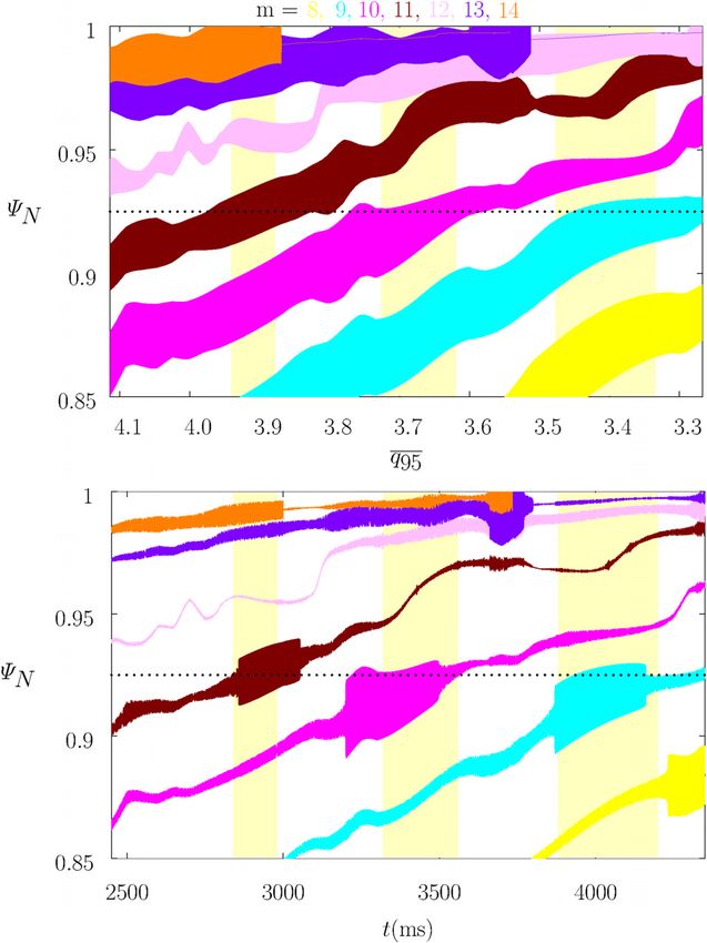
Physics of Plasmas ARTICLE scitation.org/journal/php
sR ð^r Þ ¼ l0 r 2 ree ð^r Þ Qee X
00 ð^
r Þ, where ree is the classical plasma parallel ^ ^ dYk ^ kk0 ðcos nkk0 Yk0
W k þ d k Sk ^ k Xk ¼
- E
electrical conductivity, and Qee 00 , which is defined in Sec. B of Ref. 24, is d^t k0 ¼1;K
a dimensionless parameter that specifies the corrections to this
conductivity due to neoclassical effects and the presence of plasma ^ kk ^v k sin fk ;
þ sin nkk0 Xk0 Þ þ E
impurities. Also, sA ¼ ½l0 qð0Þ a2 =B20 1=2 is a convenient scale time, (20)
qðrÞ is the plasma mass density profile, and ^t ¼ t=sA . Finally,
Wk ¼ B0 R0 W ^ k eiuk is the reconnected magnetic flux at the kth ratio- where
nal surface, vk ¼ B0 R0 ^v k eifk is a measure of the vacuum magnetic 1=2
flux at the kth rational surface (in fact, E ^ kk vk is equivalent to Esv Wv in ^ k ¼ 2I q
W ðXk2 þ Yk2 Þ1=4 : (21)
^ kk0 einkk0 is the toroidal tearing stability matrix.16 ^a ^r k g s ^r
Sec. II), and Ekk0 ¼ E k
Here, W ^ k > 0; uk ; ^ v k > 0, fk, E ^ kk0 > 0, and nkk0 are all real
Equations (19)–(21) are the toroidal generalizations of Eqs. (9)–(11),
quantities. respectively.
Note that the EPEC code calculates the elements of the toroidal
tearing mode stability matrix, Ekk0 , making use of a high-q approxima-
tion.24 On the other hand, the vk, which specify the ideal response of C. Plasma angular velocity evolution
the plasma to the applied RMP, are calculated by the GPEC code.31 Our system of equations is completed by the time evolution
Equation (13) represents a minor improvement to Eq. (D1) of equations for the ak;p and bk;p parameters. These equations specify
Ref. 24 in which the interpolation between the linear and nonlinear how the plasma poloidal and toroidal angular velocity profiles are
regimes is performed in a slightly more accurate manner. [To be modified by the electromagnetic torques that develop within the
more exact, in Ref. 24, ðW ^ k þ ^d k Þ S k is effectively replaced by plasma, in response to the applied RMP, and how these modifications
^ k þ hk ^d k Þ S k , where hk ¼ ð2 I =^a Þ ðq=g sÞ1=2 . The additional affect the natural frequencies. The evolution equations take the form24
ðW ^r k
! 2
factor of hk is spurious. Fortunately, hk is an Oð1Þ parameter.] j21;p m2k yp ð^r k Þ
2 dak;p 1 ^ k ; (22)
Equation (D6) of Ref. 24 is modified such that ð1 þ 2 qk Þ þ þ ak;p ¼ 2 dT
d^t ^s Mk ^s hk ^ k ^a 2 J2 ðj1;p Þ
q
2
duk X
^ ^
W k þ dk Sk ^k ¼
- ^ k0 sin ðuk uk0 nkk0 Þ
^ kk0 W
E dbk;p j20;p n2 zp ð^r k Þ
þ b ¼ 2 dT^ k; (23)
d^t k0 ¼1;K d^t ^s Mk k;p q ^ k J1 ðj0;p Þ
^ kk ^v k sin ðuk fk Þ;
E ð17Þ
where
where X
^k ¼
dT ^kW
^ kk0 W
E ^ k0 sin ðuk uk0 nkk0 Þ
p¼1;P p¼1;P k0 ¼1;K
X mk yp ð^r k Þ X zp ð^r k Þ
^ k ð^t Þ ¼ -
- ^ k0 ak0 ;p ð^t Þ b 0 ð^t Þ; ^ k ^v k sin ðuk fk Þ:
^ kk W
þE (24)
m 0 y ð^r 0 Þ
k0 ¼1;K k p k
z ð^r 0 Þ k ;p
k0 ¼1;K p k
(18) Here, qk ¼ mk =n; q ^ k ¼ qð^r k Þ=qð0Þ; ^s Mk ¼ a2 =½v?/ ð^r k Þ sA , and
shk ¼ sh ð^r k Þ=sA . Moreover, v?/ ð^r k Þ is the toroidal perpendicular
^ k0 ¼ -k0 sA ; yp ð^r Þ ¼ J1 ðj1;p ^r Þ=^r , and zp ð^r Þ ¼ J0 ðj0;p ^r Þ. Here, -k0
- momentum diffusivity profile, whereas
is the so-called “natural frequency” (in the absence of the RMP) at
2
the kth rational surface; this quantity is defined as the helical phase ^r ^a sii ð^r Þ
velocity of a naturally unstable island chain, resonant at the surface, sh ð^r Þ ¼ (25)
qð^r Þ li00 ð^r Þ
in the absence of an RMP (or any other island chains).
Furthermore, Jm ðzÞ is a standard Bessel function, and jm;p denotes is the poloidal flow damping time profile. Finally, sii is the classical
the pth zero of this function. Finally, P is a positive integer that is ion–ion collision time, and li00 is a dimensionless neoclassical viscosity
much larger than unity. parameter that is defined in Sec. B of Ref. 24.
Equation (17) represents a major improvement to Eq. (D6) of Once the natural frequencies, in the absence of the RMP, have
Ref. 24 that takes into account the finite slip-frequencies of the mag- been specified, Eqs. (18) and (19)–(24), form a complete set.
netic island chains induced at the various rational surfaces in the
IV. EPEC MODELING OF DIII-D DISCHARGE #145380
plasma. In the absence of a finite slip-frequency, the right-hand side of
Eq. (17) would be zero. A. Introduction
If we define Xk ¼ W ^ k cos uk and Yk ¼ W ^ k sin uk , then Eqs. (13) DIII-D discharge #145380 is an ITER-similar-shape (ISS), edge-
and (17) are more conveniently written in the nonsingular (when localized-modeling, H-mode discharge in which the plasma current is
W^ k ¼ 0) forms slowly ramped in order to scan the magnetic safety-factor.32,33 This
discharge is described in more detail in Sec. III B of Ref. 25. In addi-
X
^ k þ ^d k S k dXk þ -
W ^ k Yk ¼ ^ kk0 ðcos nkk0 Xk0 sin nkk0 Yk0 Þ
E
tion, Fig. 1 of Ref. 25 gives an overview of the discharge, whereas
d^t Figs. 2 and 3 show the plasma equilibrium and the plasma profiles,
k0 ¼1;K
respectively, at the commencement of the current ramp. A static RMP
^ kk ^v k cos fk ;
þE ð19Þ is applied to the plasma by running steady n ¼ 3 currents through the
Phys. Plasmas 28, 022503 (2021); doi: 10.1063/5.0035874 28, 022503-4
Published under license by AIP Publishing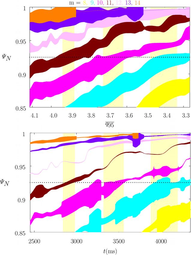
Physics of Plasmas                                                                                  ARTICLE               scitation.org/journal/php

    I-coil system.34 Three windows of ELM suppression are evident in Fig.
    1 of Ref. 25: the first occurs when t ’ 2900 ms and q95 ’ 3:91; the
    second occurs when t ¼ 3400 ms and q95 ’ 3:66; and the third occurs
    when t ’ 4000 ms and q95 ’ 3:41. Here, q95 is the safety-factor at the
    95% flux-surface.

    B. Relaxation of no-slip constraint
         As is discussed in Ref. 25, the best agreement between the predic-
    tions of the EPEC code and experimental observations is obtained by
    assuming that the unperturbed natural frequencies at the various ratio-
    nal surfaces in the plasma are determined by the local equilibrium
    E  B velocity. In other words,
                                  -k0 ¼ n xE ð^r k Þ;                  (26)
    where xE ð^r Þ ¼ dU=dWp . Here, Uð^r Þ is the equilibrium scalar elec-
    tric potential (in the absence of the RMP), and Wp ð^r Þ the equilibrium
    poloidal magnetic flux (divided by 2p). Equation (26) holds at every
    rational surface in both of the simulations discussed in Secs. IV B 1
    and IV B 2.

    1. No-slip constraint imposed
          In our first simulation, the no-slip constraint is imposed at all
    rational surfaces in the plasma. This implies that the resonant response
    model at the kth rational surface consists of Eqs. (13) and (17), with
    the right-hand side of the latter equation set to zero; in other words,
    the slip-frequency is set to zero at the kth rational surface.
          The upper panel of Fig. 1 shows the natural frequencies, in the
    absence of the RMP, of the various n ¼ 3 tearing modes that are reso-
    nant in the pedestal of DIII-D discharge #145380, whereas the lower
    panel of Fig. 1 shows the same frequencies in the presence of the RMP.
    It is apparent that if the magnitude of the natural frequency in the
    absence of the RMP falls below about 3 krad=s then the associated           FIG. 1. Composite linear/nonlinear calculation with the no-slip constraint imposed
                                                                                at all rational surfaces, and the natural frequencies in the absence of the RMP
    tearing mode locks to the RMP (i.e., its true natural frequency becomes
                                                                                determined by the local E  B velocity. Top panel: n ¼ 3 natural frequencies, in the
    zero).                                                                      absence of RMP, as functions of the least squares linear fit to q95 vs time in DIII-D
          The upper panel of Fig. 2 shows the widths of the various mag-        discharge #145380. Bottom panel: n ¼ 3 natural frequencies, in the presence of
    netic island chains driven by the applied n ¼ 3 RMP in the absence of       RMP, as functions of time in DIII-D discharge #145380. The red, green, blue, yel-
    shielding due to plasma flow, whereas the lower panel shows the same         low, cyan, magenta, brown, pink, purple, and orange curves correspond to m ¼ 5,
    widths in the presence of shielding. It is apparent that the predicted      6, 7, 8, 9, 10, 11, 12, 13, and 14, respectively. The yellow vertical bands indicate
                                                                                the ELM-suppression windows.
    island widths are generally much smaller than the “vacuum” island
    widths (i.e., the widths in the absence of shielding), as a consequence
    of the shielding of driven magnetic reconnection by plasma flow.             ELM-suppression windows, respectively. To be more exact, the island
    However, this shielding breaks down at various rational surfaces when       chains are located at the top of the pedestal (i.e., WN ¼ 0:925) and
    the associated natural frequency is zero (see the lower panel of Fig. 2).   also occur in roughly the correct q95 ranges. This is consistent with the
    In this situation, the driven island width is similar to the vacuum         hypothesis that the formation of locked magnetic island chains at the
    island width.                                                               top of the pedestal causes ELM mitigation/suppression. Here,
          According to the prevailing hypothesis, RMP-induced ELM mitiga-       WN ð^r Þ ¼ ½Wp ð^r Þ  Wp ð0Þ=½Wp ð^a Þ  Wp ð0Þ is the conventional
    tion/suppression in an H-mode tokamak discharge occurs when a com-          normalized equilibrium poloidal magnetic flux.
    paratively wide, locked, magnetic island chain is generated at the top of         In principle, the calculation shown in Figs. 1 and 2 is a repeat of
    the pedestal.35,36 The temperature and density flattening associated with    one performed in Ref. 25. In practice, there is a slight difference
    the chain is presumed to limit the radial expansion of the pedestal, and,   between the two calculations because the expression for the linear layer
    thereby, prevent it from attaining a width sufficient to destabilize         width used in Eq. (D1) of Ref. 24 (which specifies the island width evo-
    peeling-ballooning modes37 (which are thought to trigger ELMs).32           lution equation employed in Ref. 25), which was only intended to be
          According to Fig. 2, the comparatively wide, m ¼ 11 (brown),          approximate, is slightly inaccurate [because it contains a spurious fac-
                                                                                                          1=2
    m ¼ 10 (magenta), and m ¼ 9 (cyan), locked magnetic island chains           tor of (2 I =^a Þ ðq=g sÞ^r k —see Sec. III A]. This accounts for the very
    which are predicted to be driven by the RMP in the pedestal of DIII-D       minor differences between Figs. 1 and 2 in this paper and Figs. 8 and 9
    discharge #145380 line up fairly well with the first, second, and third,     in Ref. 25.

Phys. Plasmas 28, 022503 (2021); doi: 10.1063/5.0035874                                                                                                  28, 022503-5
Published under license by AIP Publishing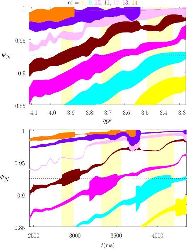
Physics of Plasmas ARTICLE scitation.org/journal/php
FIG. 2. Composite linear/nonlinear calculation with the no-slip constraint imposed FIG. 3. Composite linear/nonlinear calculation with the no-slip constraint relaxed at all
at all rational surfaces, and the natural frequencies in the absence of the RMP rational surfaces, and the natural frequencies in the absence of the RMP determined
determined by the local E B velocity. Top panel: full n ¼ 3 vacuum island widths by the local E B velocity. Top panel: n ¼ 3 natural frequencies, in the absence of
as functions of the least squares linear fit to q95 vs time in DIII-D discharge RMP, as functions of the least squares linear fit to q95 vs time in DIII-D discharge
#145380. Bottom panel: full n ¼ 3 island widths as functions of time in DIII-D dis- #145380. Bottom panel: n ¼ 3 natural frequencies, in the presence of RMP, as func-
charge #145380. The yellow, cyan, magenta, brown, pink, purple, and orange areas tions of time in DIII-D discharge #145380. The red, green, blue, yellow, cyan, magenta,
correspond to m ¼ 8, 9, 10, 11, 12, 13, and 14, respectively. The yellow vertical brown, pink, purple, and orange curves correspond to m ¼ 5, 6, 7, 8, 9, 10, 11, 12, 13,
bands indicate the ELM-suppression/mitigation windows. The horizontal dotted lines and 14, respectively. The yellow vertical bands indicate the ELM-suppression windows.
indicate the top of the pedestal, WN ¼ 0:925.
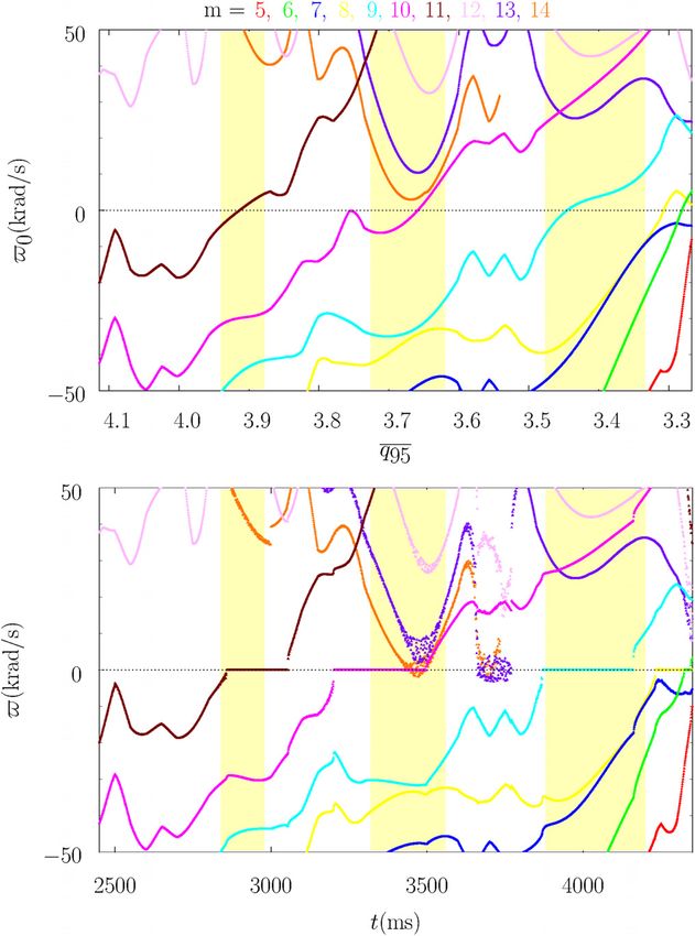
2. No-slip constraint relaxed shielding of driven magnetic reconnection). It can be seen from Fig.
5 that if the no-slip constraint is imposed, then the RMP-modified
In our second simulation, the no-slip constraint is relaxed at all natural frequencies of locked magnetic island chains are exactly
rational surfaces in the plasma. This implies that the resonant response zero. On the other hand, if the no-slip constraint is relaxed, then
model at the kth rational surface consists of Eqs. (19) and (20). Figures 3 locked magnetic island chains possess small but finite RMP-
and 4 show analogous data to Figs. 1 and 2, respectively. Figure 5 shows modified natural frequencies, because the local plasma flow is able
details of the bottom panels of Figs. 1 and 3, in order to better illustrate to slip through the stationary chains to some extent. However, the
the island chain dynamics when the RMP-modified natural frequencies degree of slippage for a fully developed locked magnetic island
of the various n ¼ 3 tearing modes in plasma are comparatively small. chain is comparatively small (i.e., no more than 0:5 krad=s), which
A comparison of Figs. 1 and 3, as well as an examination of helps explain why the no-slip constraint can be used to accurately
Fig. 5, reveals that the relaxation of the no-slip constraint facilitates predict the dynamics of wide magnetic island chains in tokamaks
the locking of magnetic island chains to the RMP to a relatively and reversed field pinches.38
modest degree. (Here, by locking, we mean a reduction in the It is remarkable that the results shown in Figs. 1–3 are so similar,
RMP-modified natural frequency to a value close to zero.) This is given that the relaxation of the no-slip constraint leads to a radical
not surprising because relaxation of the no-slip constraint clearly modification of the dynamics of non-locked magnetic island chains.
weakens the coupling between a given magnetic island chain and When the no-slip constraint is imposed, the widths of magnetic island
the local plasma flow (which is ultimately responsible for the chains that are unable to lock to the RMP are forced to pulsate,
Phys. Plasmas 28, 022503 (2021); doi: 10.1063/5.0035874 28, 022503-6
Published under license by AIP Publishing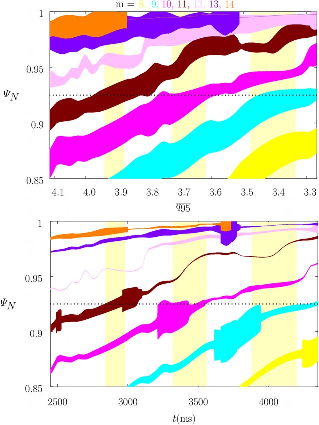
Physics of Plasmas                                                                                                   ARTICLE                scitation.org/journal/php

     FIG. 4. Composite linear/nonlinear calculation with the no-slip constraint relaxed at all   FIG. 5. Top panel: details of the bottom panel of Fig. 1. Bottom panel: details of the
     rational surfaces, and the natural frequencies in the absence of the RMP determined         bottom panel of Fig. 3.
     by the local E  B velocity. Top panel: full n ¼ 3 vacuum island widths as functions of
     the least squares linear fit to q95 vs time in DIII-D discharge #145380. Bottom panel:
     full n ¼ 3 island widths as functions of time in DIII-D discharge #145380. The yellow,
     cyan, magenta, brown, pink, purple, and orange areas correspond to m ¼ 8, 9, 10, 11,                              -k0 ¼ - ln k  n ðxE þ xe Þ^r k ;                        (27)
     12, 13, and 14, respectively. The yellow vertical bands indicate the ELM-suppression
     windows. The horizontal dotted lines indicate the top of the pedestal, WN ¼ 0:925.          where xe ð^r Þ ¼ ðTe =eÞ d ln pe =dWp . Here, e is the magnitude of the
                                                                                                 electron charge, pe ð^r Þ the equilibrium (i.e., in the absence of the RMP)
    periodically falling to zero, because the helical phases of the chains are                   electron pressure, and Te ð^r Þ the equilibrium electron temperature.
    forced to continuously increase (or decrease) by their non-zero natural                            According to nonlinear tearing mode theory, in the absence of
    frequencies.26–28,39 On the other hand, when the no-slip constraint is                       the RMP, the natural frequency of the tearing mode resonant at the
    relaxed, the widths of magnetic island chains that are unable to lock to                     kth rational surface is given by24
    the RMP have steady values, because the chains can slip with respect
                                                                                                                                                             gi
    to the local plasma flow, which means that they can have fixed helical                              -k0 ¼ -nlk  n xE þ 1  Lii00 þ Lii01                      xi
                                                                                                                                                        1 þ gi
    phases despite the fact that their natural frequencies are non-zero.
         Unfortunately, although the relaxation of the no-slip constraint is                                                             gI
                                                                                                                      LiI00  LiI01               xI ;                 (28)
    undoubtedly correct, from a physics standpoint, it does not lead to an                                                             1 þ gI           ^r k
    obvious improvement in agreement between the predictions of the
    EPEC model and experimental results.                                                         where xa ð^r Þ ¼ ðTa =Za eÞ d ln pa =dWp , ga ð^r Þ ¼ d ln Ta =d ln na ,
                                                                                                 for a ¼ i; I. Here, Zi, ni ð^r Þ; Ti ð^r Þ, and pi ð^r Þ ¼ ni Ti are the charge
                                                                                                 number, equilibrium number density, equilibrium temperature, and
    C. Improved interpolation between linear
                                                                                                 equilibrium pressure of the majority (thermal) ions, respectively,
    and nonlinear resonant response regimes                                                      whereas ZI, nI, TI, pI ¼ nI TI are the corresponding quantities for the
         According to linear tearing mode theory, in the absence of the                          impurity ions. Furthermore, Lii00 ð^r Þ; Lii01 ð^r Þ; LII00 ð^r Þ, and LII01 ð^r Þ
    RMP, the natural frequency of the tearing mode resonant at the kth                           are dimensionless neoclassical parameters that are defined in Sec. B of
    rational surface is given by13,40–42                                                         Ref. 24.

Phys. Plasmas 28, 022503 (2021); doi: 10.1063/5.0035874                                                                                                                    28, 022503-7
Published under license by AIP Publishing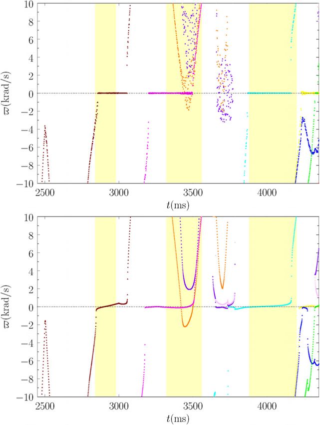
Physics of Plasmas                                                                                                  ARTICLE               scitation.org/journal/php

         Finally, the best agreement between theory and experiment is
    obtained by assuming that, in the absence of the RMP, the natural fre-
    quency of the tearing mode resonant at the kth rational surface is given
    by Eq. (26).25,43

    1. Linear calculation
         For the sake of comparison, we shall first perform a purely
    linear calculation. Thus, the resonant plasma response model at
    the kth rational surface consists of Eqs. (19) and (20), with W^ k set
    to zero. Moreover, in the absence of the RMP, the natural fre-
    quency at the kth rational surface is specified by Eq. (27). Figures 6
    and 7 show the natural frequencies in the absence, and in the pres-
    ence, of the RMP, as well as the vacuum islands widths and the
    actual island widths.
         It can be seen by a comparison between Figs. 1–4, on the one
    hand, and Figs. 6 and 7, on the other, that the linear calculation

                                                                                                FIG. 7. Linear calculation with the no-slip constraint relaxed at all rational surfa-
                                                                                                ces, and the natural frequencies in the absence of the RMP determined by lin-
                                                                                                ear theory. Top panel: full n ¼ 3 vacuum island widths as functions of the least
                                                                                                squares linear fit to q95 vs time in DIII-D discharge #145380. Bottom panel: full
                                                                                                n ¼ 3 island widths as functions of time in DIII-D discharge #145380. The yel-
                                                                                                low, cyan, magenta, brown, pink, purple, and orange areas correspond to
                                                                                                m ¼ 8, 9, 10, 11, 12, 13, and 14, respectively. The yellow vertical bands indicate
                                                                                                the ELM-suppression windows. The horizontal dotted lines indicate the top of
                                                                                                the pedestal, WN ¼ 0:925.

                                                                                                very significantly overestimates how easy it is for magnetic island
                                                                                                chains to lock to the RMP. We can say this because the m ¼ 9
                                                                                                (cyan) magnetic island chain, for example, in the lower panel of
                                                                                                Fig. 7 exhibits virtually no shielding due to plasma flow over a
                                                                                                wide range of different q95 values. The reason for the lack of effec-
                                                                                                tive flow shielding is that the linear slip-frequency is compara-
                                                                                                tively high, because the linear layer width is comparatively
                                                                                                narrow, which greatly facilitates the locking of magnetic island
                                                                                                chains to the RMP. However, the true slip-frequency becomes less
     FIG. 6. Linear calculation with the no-slip constraint relaxed at all rational surfaces,   than the linear slip-frequency as soon as the island width exceeds
     and the natural frequencies in the absence of the RMP determined by linear theory.
                                                                                                the linear layer width.
     Top panel: n ¼ 3 natural frequencies, in the absence of RMP, as functions of the
     least squares linear fit to q95 vs time in DIII-D discharge #145380. Bottom panel:
     n ¼ 3 natural frequencies, in the presence of RMP, as functions of time in DIII-D          2. Composite linear/nonlinear calculation
     discharge #145380. The red, green, blue, yellow, cyan, magenta, brown, pink, pur-
     ple, and orange curves correspond to m ¼ 5, 6, 7, 8, 9, 10, 11, 12, 13, and 14,                 In our composite linear/nonlinear calculation, the resonant
     respectively. The yellow vertical bands indicate the ELM-suppression windows.              plasma response model at the kth rational surface consists of Eqs. (19)

Phys. Plasmas 28, 022503 (2021); doi: 10.1063/5.0035874                                                                                                                  28, 022503-8
Published under license by AIP Publishing
Physics of Plasmas                                                                                               ARTICLE               scitation.org/journal/php

    and (20). Moreover, in the absence of the RMP, the natural frequency
    at the kth rational surface is specified by
                        - ln k þ ð-ebk  - ln k  -nlk Þ xk þ -nlk xk2
                -k0 ¼                                                  ;             (29)
                                        1  xk þ xk2
    where xk ¼ W  ^ k =^d k . It follows that -k0 ¼ - ln k in the linear regime,
    xk  1; -k0 ¼ -nlk in the nonlinear regime, xk  1; and -k0 ¼ -ebk
    when xk ¼ 1. (Note that -ebk generally lies between - ln k and -nlk .)
    Figures 8 and 9 show the natural frequencies in the absence, and in the
    presence, of the RMP, as well as the vacuum islands widths and the
    actual island widths.
         It can be seen that the results of the composite linear/nonlin-
    ear simulation shown in Figs. 8 and 9 are similar to the results of
    the nonlinear simulations shown in Figs. 1–4, but significantly dif-
    ferent to the results of the linear simulation shown in Figs. 6 and 7.
    In particular, the composite simulations and the nonlinear

                                                                                             FIG. 9. Composite linear/nonlinear calculation with the no-slip constraint relaxed at
                                                                                             all rational surfaces, and the natural frequencies in the absence of the RMP deter-
                                                                                             mined by composite linear/nonlinear theory. Top panel: full n ¼ 3 vacuum island
                                                                                             widths as functions of the least squares linear fit to q95 vs time in DIII-D discharge
                                                                                             #145380. Bottom panel: full n ¼ 3 island widths as functions of time in DIII-D dis-
                                                                                             charge #145380. The yellow, cyan, magenta, brown, pink, purple, and orange areas
                                                                                             correspond to m ¼ 8, 9, 10, 11, 12, 13, and 14, respectively. The yellow vertical
                                                                                             bands indicate the ELM-suppression windows. The horizontal dotted lines indicate
                                                                                             the top of the pedestal, WN ¼ 0:925.

                                                                                             simulations indicate that a magnetic island chain can only lock to
                                                                                             the RMP when the magnitude of its natural frequency falls below
                                                                                             about 3 krad/s, whereas the linear simulations indicate that locking
                                                                                             can occur when the magnitude of the natural frequency falls below
                                                                                             about 6 krad/s. The fact that the composite calculation is much
                                                                                             more similar to the nonlinear simulation, and significantly different
                                                                                             to the linear simulation, confirms the conclusion reached in Ref. 28
                                                                                             that the response of a typical H-mode tokamak plasma to an RMP
                                                                                             is not governed by linear theory, because the driven island widths
     FIG. 8. Composite linear/nonlinear calculation with the no-slip constraint relaxed at   exceed the very narrow linear layer widths, even when driven
     all rational surfaces, and the natural frequencies in the absence of the RMP deter-     reconnection is strongly suppressed by plasma flow.
     mined by composite linear/nonlinear theory. Top panel: n ¼ 3 natural frequencies,             Intriguingly, the composite linear/nonlinear model fairly accu-
     in the absence of RMP, as functions of the least squares linear fit to q95 vs time in    rately predicts the widths of the three ELM mitigation/suppression
     DIII-D discharge #145380. Bottom panel: n ¼ 3 natural frequencies, in the presence
                                                                                             windows in q95 (assuming that the windows correspond to the forma-
     of RMP, as functions of time in DIII-D discharge #145380. The red, green, blue,
     yellow, cyan, magenta, brown, pink, purple, and orange curves correspond to             tion of wide locked magnetic island chains at the top of the pedestal).
     m ¼ 5, 6, 7, 8, 9, 10, 11, 12, 13, and 14, respectively. The yellow vertical bands      However, the windows are not centered on the correct q95 values. We
     indicate the ELM-suppression windows.                                                   conclude that Eq. (26) gives a more accurate prediction for the natural

Phys. Plasmas 28, 022503 (2021); doi: 10.1063/5.0035874                                                                                                               28, 022503-9
Published under license by AIP Publishing
Physics of Plasmas ARTICLE scitation.org/journal/php
frequencies, in the absence of the RMP, than Eq. (29) (because the for- This report was prepared as an account of work sponsored by
mer equation leads to windows that are centered on the correct q95 val- an agency of the United States Government. Neither the United
ues). There are a number of possible explanations for this discrepancy. States Government nor any agency thereof, nor any of their employ-
First, the nonlinear tearing mode theory which leads to the prediction ees, makes any warranty, express or implied, or assumes any legal lia-
(28) for the unperturbed natural frequency of a nonlinear island chain bility or responsibility for the accuracy, completeness, or usefulness
may be missing an important element. (For example, kinetic effects,43 of any information, apparatus, product, or process disclosed, or rep-
or the influence of neoclassical toroidal flow damping.) Second, the resents that its use would not infringe privately owned rights.
errors in the experimental data, and, in particular, the errors in the Reference herein to any specific commercial product, process, or ser-
experimental E B velocity profile, may be too large for EPEC to vice by trade name, trademark, manufacturer, or otherwise does not
calculate the unperturbed natural frequencies with sufficient precision necessarily constitute or imply its endorsement, recommendation, or
to accurately determine the locations of the ELM suppression windows favoring by the United States Government or any agency thereof.
in q95 space. The views and opinions of authors expressed herein do not necessar-
ily state or reflect those of the United States Government or any
V. SUMMARY agency thereof.
We have developed an improved resonant plasma response
model that more accurately captures the physics of the interaction ACKNOWLEDGMENTS
between a tokamak plasma and an RMP. The model interpolates
between the linear and the nonlinear response regimes and takes into This research was directly funded by the U.S. Department of
account the fact that the slip-frequency is non-zero in the nonlinear Energy, Office of Science, Office of Fusion Energy Sciences, under
regime. Our improved model has been incorporated into the EPEC Contract No. DE-FG02-04ER54742, and incorporates work funded
toroidal asymptotic matching code.25 The modified EPEC code is used by the U.S. Department of Energy, Office of Science, Office of
to model RMP-induced ELM mitigation/suppression in DIII-D H- Fusion Energy Sciences, using the DIII-D National Fusion Facility,
mode discharge #145380. a DOE Office of Science user facility, under Contract No. DE-
We find that allowing for a finite slip-frequency (i.e., relaxing the FC02-04ER54698.
so-called no-slip constraint) slightly facilitates the locking of driven DATA AVAILABILITY
magnetic island chains to the RMP. (Here, by locking, we mean the
The data that support the findings of this study are available
reduction of the RMP-modified natural frequency of a given chain to
from the corresponding author upon reasonable request.
a value that is very close to zero.) In fact, there is surprisingly little dif-
ference between EPEC simulations that impose the no-slip constraint
at the various rational surfaces in the plasma and those in which the REFERENCES
1
constraint is relaxed. This is true despite the fact that the nature of J. T. Scoville and R. J. LaHaye, Nucl. Fusion 43, 250 (2003).
2
J.-K. Park, M. J. Schaffer, J. E. Menard, and A. H. Boozer, Phys. Rev. Lett. 99,
non-locked island solutions is radically different in the two cases (in
195003 (2007).
the first case, the widths of the island chains driven at the rational sur- 3
N. M. Ferraro, J.-K. Park, C. E. Myers, A. Brooks, S. P. Gerhardt, J. E. Menard,
faces pulsate, in the second they remain steady). S. Munaretto, and M. L. Reinke, Nucl. Fusion 59, 086021 (2019).
4
Our calculations confirm the conclusion reached in Ref. 28 that T. E. Evans, R. A. Moyer, J. G. Watkins, P. R. Thomas, T. H. Osborne, J. A.
the response of a typical H-mode tokamak plasma to an RMP cannot Boedo, M. E. Fenstermacher, K. H. Finken, R. J. Groebner, M. Groth et al.,
be accurately modeled by linear theory. Our calculations also confirm Phys. Rev. Lett. 92, 235003 (2004).
5
Y. Liang, H. R. Koslowski, P. R. Thomas, E. Nardon, B. Alper, P. Andrew, Y.
the conclusion reached in Ref. 25 that the best agreement between the- Andrew, G. Arnoux, Y. Baranov, M. Becoulet et al., Phys. Rev. Lett. 98, 265004
ory and observations is obtained by assuming that the natural frequen- (2007).
cies of tearing modes, in the absence of the RMP, are determined by 6
W. Suttrop, T. Eich, J. C. Fuchs, S. G€ unter, A. Janzer, A. Herrmann, A.
the local E B velocity. Kallenbach, P. T. Lang, T. Lunt, M. Maraschek et al., Phys. Rev. Lett. 106,
None of the improvements to the EPEC model described in this 225004 (2011).
7
Y. M. Jeon, J.-K. Park, S. W. Yoon, W. H. Ko, S. G. Lee, K. D. Lee, G. S. Yun,
paper lead to markedly better agreement between the predictions of
Y. U. Nam, W. C. Kim, J.-G. Kwak, K. S. Lee, H. K. Kim, H. L. Yang et al.,
the model and experimental results. In fact, it is clear that the compo- Phys. Rev. Lett. 109, 035004 (2012).
nent of the model that has, by far, the most influence on the level of 8
A. Kirk, I. T. Chapman, Y. Liu, P. Cahyna, P. Denner, G. Fishpool, C. J. Ham,
agreement with experimental results is the calculation of the natural J. R. Harrison, Y. Liang, E. Nardon, S. Saarelma, R. Scannell, A. J. Thornton,
frequencies of tearing modes in the absence of the RMP. This suggests and MAST Team, Nucl. Fusion 53, 043007 (2013).
9
that there may be a missing element in this calculation; for example, T. Sun, Y. Liang, Y. Q. Liu, S. Gu, X. Yang, W. Guo, T. Shi, M. Jia, L. Wang, B.
Lyu et al., Phys. Rev. Lett. 117, 115001 (2016).
kinetic effects,43 or the influence of neoclassical toroidal flow damping. 10
H. P. Furth, J. Killeen, and M. N. Rosenbluth, Phys. Fluids 6, 459 (1963).
Another possibility is that the errors in the experimental data, and, in 11
B. Coppi, J. M. Greene, and J. L. Johnson, Nucl. Fusion 6, 101 (1966).
particular, the errors in the experimental E B velocity profile, may 12
P. H. Rutherford, Phys. Fluids 16, 1903 (1973).
13
be too large for the EPEC model to calculate unperturbed natural fre- G. Ara, B. Basu, B. Coppi, G. Laval, M. N. Rosenbluth, and B. V. Waddell, Ann.
quencies with sufficient precision to accurately determine the locations Phys. 112, 443 (1978).
14
A. Pletzer and R. L. Dewar, J. Plasma Phys. 45, 427 (1991).
of ELM-suppression windows in q95 space. Further detailed compari- 15
R. Fitzpatrick, Nucl. Fusion 33, 1049 (1993).
sons between the predictions of the model and experimental results 16
R. Fitzpatrick, R. J. Hastie, T. J. Martin, and C. M. Roach, Nucl. Fusion 33,
from a wide range of different H-mode plasmas in different machines 1533 (1993).
17
may help to further characterize the source of the disagreement. S. Tokuda, Nucl. Fusion 41, 1037 (2001).
Phys. Plasmas 28, 022503 (2021); doi: 10.1063/5.0035874 28, 022503-10
Published under license by AIP PublishingPhysics of Plasmas ARTICLE scitation.org/journal/php
18 33
D. P. Brennan, R. J. La Haye, A. D. Turnbull, M. S. Chu, T. H. Jensen, L. L. Lao, Q. M. Hu, R. Nazikian, B. A. Grierson, N. C. Logan, D. M. Orlov, C. Paz-
T. C. Luce, P. A. Politzer, and E. J. Strait, Phys. Plasmas 10, 1643 (2003). Solden, and Q. Yu, Phys. Rev. Lett. 125, 045001 (2020).
19 34
A. H. Glasser, Z. R. Wang, and J.-K. Park, Phys. Plasmas 23, 112506 (2016). G. L. Jackson, P. M. Anderson, J. Bialek, W. P. Cary, G. L. Campbell, A. M.
20
R. Fitzpatrick, Phys. Plasmas 24, 072506 (2017). Garofalo, R. Hatcher, A. G. Kellman, R. J. LaHaye, A. Nagy et al., in
21
P. H. Rutherford, in Basic Physical Processes of Toroidal Fusion Plasmas: Proceedings of the 30th EPS Conference on Controlled Fusion and Plasma
Proceedings of the Course and Workshop, Varenna, 1985 (Commission of the Physics, St. Petersburg, Russia (2003), CD-ROM, p. P-4.47.
35
European Communities, Brussels, 1985), Vol. 2, p. 531. Q. M. Hu, R. Nazikian, B. A. Grierson, N. C. Logan, J.-K. Park, C. Paz-Soldan,
22
L. G. Eliseev, N. V. Ivanov, A. M. Kakurin, A. V. Melnikov, and S. V. Perfilov, and Q. Yu, Phys. Plasmas 26, 120702 (2019).
36
Phys. Plasmas 22, 052504 (2015). Q. M. Hu, R. Nazikian, B. A. Grierson, N. C. Logan, C. Paz-Soldan, and Q. Yu,
23
W. Huang and P. Zhu, Phys. Plasmas 27, 022514 (2020). Nucl. Fusion 60, 076001 (2020).
24 37
R. Fitzpatrick and A. O. Nelson, Phys. Plasmas 27, 072501 (2020). J. W. Connor, R. J. Hastie, H. R. Wilson, and R. L. Miller, Phys. Plasmas 5,
25
R. Fitzpatrick, Phys. Plasmas 27, 102511 (2020). 2687 (1998).
26 38
R. Fitzpatrick, Phys. Plasmas 5, 3325 (1998). B. E. Chapman, R. Fitzpatrick, D. Craig, P. Martin, and G. Spizzo, Phys.
27
R. Fitzpatrick, Phys. Plasmas 21, 092513 (2014). Plasmas 11, 2156 (2004).
28 39
R. Fitzpatrick, Phys. Plasmas 27, 042506 (2020). R. Fitzpatrick, Phys. Plasmas 25, 112505 (2018).
29 40
R. Fitzpatrick, Phys. Plasmas 10, 2304 (2003). M. Becoulet, F. Orain, P. Maget, N. Mellet, X. Garbet, E. Nardon, G. T. A.
30
A. N. Chudnovskiy, Y. V. Gvozdkov, N. V. Ivanov, A. M. Kakurin, A. A. Huysmans, T. Caspar, A. Loarte, P. Cayna et al., Nucl. Fusion 52, 054003 (2012).
41
Medvedev, I. I. Orlovskiy, Y. D. Pavlov, V. V. Piterskiy, V. D. Pustovitov, M. B. N. M. Ferraro, Phys. Plasmas 19, 056105 (2012).
42
Safonova, V. V. Volkov, and the T-10 Team, Nucl. Fusion 43, 681 (2003). F. Orain, M. Becoulet, G. Dif-Pradalier, G. T. A. Huysmans, S. Pamela, E.
31
J.-K. Park and N. C. Logan, Phys. Plasmas 24, 032505 (2017). Nardon, C. Passeron, G. Latu, V. Grandgirard, A. Fil et al., Phys. Plasmas 20,
32
P. B. Snyder, T. H. Osboune, K. H. Burrell, R. J. Groebner, A. W. Leonard, R. 102510 (2013).
43
Nazikian, D. M. Orlov, O. Schmitz, M. R. Wade, and H. R. Wilson, Phys. M. F. Heyn, I. B. Ivanov, S. V. Kasilov, W. Kernbichler, I. Joseph, R. A. Moyer,
Plasmas 19, 056115 (2012). and A. M. Runov, Nucl. Fusion 48, 024005 (2008).
Phys. Plasmas 28, 022503 (2021); doi: 10.1063/5.0035874 28, 022503-11
Published under license by AIP PublishingYou can also read