Low noise moving target detection in high resolution radar using binary codes
←
→
Page content transcription
If your browser does not render page correctly, please read the page content below
Alotaibi EURASIP Journal on Advances in Signal Processing           (2021) 2021:8
https://doi.org/10.1186/s13634-020-00716-0
                                                                                                           EURASIP Journal on Advances
                                                                                                                    in Signal Processing

 RESEARCH                                                                                                                                     Open Access

Low noise moving target detection in high
resolution radar using binary codes
Majid Alotaibi

Correspondence: mmgethami@uqu.
edu.sa                                 Abstract
Department of Computer
Engineering, College of Computer       Radar technology plays a vital role in enhancing surveillance of the battlefields and
and Information Systems, Umm           physical borders, disease detection, and weather prediction. However, there exist
Al-Qura University, Makkah, Saudi      certain challenges like detecting fast-moving targets. When targets are moving at a
Arabia
                                       significantly high speed, it is not easy to detect them compared to static and slow-
                                       moving targets, which are easily detected. In this regard, the research community
                                       has, over the years, tried to improve radar technology to detect fast moving targets
                                       in presence of Doppler noise. In this paper, various binary codes have been
                                       proposed to minimize the noise peaks below the radar threshold limit to create
                                       multiple windows that enable precise information of the moving targets. These
                                       sequences also have good autocorrelation attributes to get a higher range resolution
                                       and compression ratio. Validation of the proposed method is performed using
                                       Matlab simulations. Results show that the noise amplitudes are reduced to 0.2 dB
                                       well below the prescribed threshold.
                                       Keywords: Signal-to-noise ratio, Side lobes, Ambiguity, Autocorrelation, Matlab

                                     1 Introduction
                                     Radars are a well-known object recognition system that consists of transceiver which
                                     initially transmits signals, and then, the received echo signals are used to calculate
                                     speed, distance, angle, shape, and size of objects. Radar technology finds its use exten-
                                     sively in medicine for identifying diseases, by militaries to track adversarial positions
                                     with respect to time, and various civil applications like approximate recognition of ve-
                                     hicles, sea observation, climate prediction, and to obtain certain the geological parame-
                                     ters. To accomplish the required objective of target discovery, continuous waveform
                                     (CW) radar is mainly employed to find the location of the object, as it incessantly
                                     sends the signals via transmitting end to notice the object, and the signals reflected
                                     from the object (echoes) are acknowledged at the recipient end. The key benefit of this
                                     radar is to measure its specific Doppler effect. However, due to continuous transmis-
                                     sion of signals, it produces uncertainty in the target scope and necessitates dual aerials.
                                     To reduce the uncertainty and dual antenna system, pulse radar is utilized in contem-
                                     porary systems as it gives the exact range statistics, and a single aerial is used for both
                                     transmission and reception. The aerial behaves as a transmitter in the duration of the
                                    © The Author(s). 2021, corrected publication 2021. Open Access This article is licensed under a Creative Commons Attribution 4.0
                                    International License, which permits use, sharing, adaptation, distribution and reproduction in any medium or format, as long as you
                                    give appropriate credit to the original author(s) and the source, provide a link to the Creative Commons licence, and indicate if
                                    changes were made. The images or other third party material in this article are included in the article's Creative Commons licence,
                                    unless indicated otherwise in a credit line to the material. If material is not included in the article's Creative Commons licence and
                                    your intended use is not permitted by statutory regulation or exceeds the permitted use, you will need to obtain permission directly
                                    from the copyright holder. To view a copy of this licence, visit http://creativecommons.org/licenses/by/4.0/.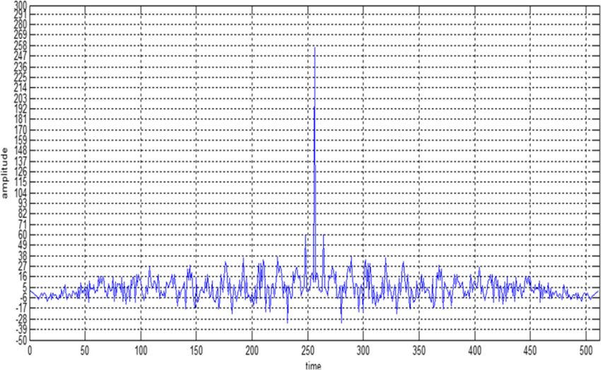
Alotaibi EURASIP Journal on Advances in Signal Processing   (2021) 2021:8                                        Page 2 of 19

                  pulse time Pdt, and it behaves as a receiver in duration of pulse time Prt. Pulse compres-
                  sion techniques have been traditionally employed to process signals in a radar system.
                  These techniques use long pulses at the transmitter side to improve the scope of target
                  detection and short duration pulses to acquire a high resolution at the recipient side. In
                  multiple-object environment, it is difficult to detect a single object which is of a smaller
                  size. Resolution plays a vital role to discriminate the required target in a multiple-
                  object environment. In art of work, pulse compression-matched filtering approach is
                  used to find the current position of the target using autocorrelation property. This ap-
                  proach optimizes the amplitude of side lobes which can hide the desired targets. To
                  achieve the side noise suppression noise, several codes such as Barker, Golay, PTM,
                  and other optimized techniques have been tested. Nevertheless, all these methods fail
                  to detect the multiple and moving target. In [1, 2], the authors optimized the target de-
                  tection using feedback and cognitive approaches. However, in both the approaches,
                  delay is increased which reduces the probability of multiple moving target detection.
                  Levanon [3] proposed an inter pulse coding technique to enhance the target detection,
                  but the approach is limited to low- and mid-range targets. Shi et al. [4] compares a
                  pseudo-random binary phase coding and the chirp modulation to estimate the per-
                  formance of target detection.
                    In this paper, several digital codes have been proposed with good autocorrelation
                  function and Doppler tolerance. These codes are used to detect the object which is
                  static or moving in multi-object ambience. The side noise in autocorrelation is opti-
                  mized, and side noise in the ambiguity plot is almost approximated to the threshold of
                  0.2 dB. The validation of designed codes is done using Matlab. In this article, we
                  propose the following:

                    i.  A method to optimize the side noise in autocorrelation function plot and improve
                        the Doppler tolerance of the codes obtained.
                    ii. Linear block code (7, 4) is used to obtain the binary sequence code of the lengths
                        128 and 256 (by performing some mathematical operations on (7, 4) codes).

                  2 Related work
                  Tian et al. [5] designed poly-phase radar codes with a lower signal-to-noise ratio (SNR)
                  by making use of the Wigner-Ville distribution (WVD). But the noise lobes were still
                  significant, and this method is suitable for electronic intelligent systems only. Kretsch-
                  mer and Lewis [6] discussed the Doppler effect of the combined poly-phase sequences
                  p1, p2, p3, and p4, and the frank codes. A comparative analysis is represented in which
                  there was 4 dB loss of the signal in a cyclic manner, and the loss increased when phase
                  shift was an odd multiple of π across the non-compressed pulses. However, when the
                  Doppler frequency is increased, p3 and p4 may fail to produce accurate results in case
                  of moving targets. Sivaswami [7] presented the repetitive Hadamard sequence which is
                  sub-complemented codes; the ambiguity functions of these codes are combined to
                  neutralize the effects of self-clutter. But this method increases hardware complexity as
                  the numbers of filters are high which are required to produce the combined effect of
                  their outputs with significant noise induced. Guey and Bell [8] presented a method to
                  obtain the measurements of the ambiguity function by using multiple signals. These
                  signals may be phase or frequency coded or combination of both phase and frequency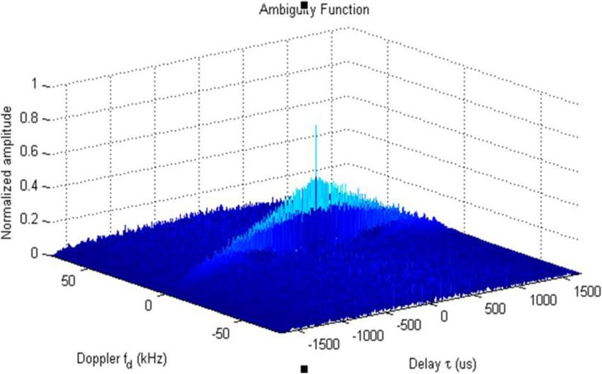
Alotaibi EURASIP Journal on Advances in Signal Processing   (2021) 2021:8                                        Page 3 of 19

                  with constant signal amplitude. However, this approach requires several radars to
                  monitor a single target which increases the hardware complexity and constraints its ap-
                  plication. The author in [9] designed the matrix of complementary sequences in which
                  the columns of the matrix forms the code vector. The codes used to form this matrix
                  are binary uni-modular complementary codes of the same length such that the autocor-
                  relation of the side lobes sums to “0”. But the complexity increases, and it is a time-
                  consuming process. Chang and Bell [10] proposed different techniques to develop se-
                  quences based on the frequency where the side lobes are minimum, and clear windows
                  are formed to detect the target which is masked. The codes were termed as a pushing
                  sequence. However, side lobe increases as the perfect error-correcting codes using lee
                  code words increases. Deng [11] proposed a hybrid algorithm for optimization which is
                  used to design polyphase codes. The hybrid algorithm used combines the method of
                  annealing and iterative selection of codes. But the iterative codes consume more time
                  when the code length is increased. And as the netted radar systems are used with an in-
                  crease in the code length, the hardware complexity also increases. When the delay in-
                  creases, the precise detection of the moving target is rarely possible.
                    Pezeshki et al. [12] used Golay complementary codes to be sequenced in pulse ampli-
                  tude modulation to mitigate the range side noise in the desired interval of Doppler, and
                  using the orthogonal frequency multiplexing, the Doppler side noise in the desired inter-
                  val range is root out. However, this method requires a library of phase codes with pairs of
                  complementary codes which is practically difficult. Deng [13] designed the binary se-
                  quence with good cross and autocorrelation function by using an optimization algorithm
                  known as annealing simulation to reduce the side noise this algorithm converges globally
                  and is robust. However, the algorithm presented is not used to its full potential as it con-
                  sumes more CPU time. Gladkova and Chebanov [14] discussed the suppression of the un-
                  desirable side peaks produced at the matched filter output when the input of uniform
                  frequency stepped pulse train is provided. This method is not capable of detecting the
                  moving targets. Levanon and Mozeson [15] discussed the suppression of grating lobes of
                  autocorrelation function using linear frequency-modulated pulses to obtain better reso-
                  lution of range. However, to make the significant suppression, the step size of normalized
                  frequency should be small, and the pulses should be high in number. Jenshak and Stiles
                  [16] presented a method of obtaining the sequence with low-error estimation of the range
                  which in turn lowers the side lobes. These codes detect only the static objects. The au-
                  thors of [17, 18] presented two different techniques to improve the Doppler tolerance of
                  moving targets. However, both the techniques maximize the mathematical complexity
                  and delay which reduces the efficiency of target detection and may not be optimum to de-
                  tect fast-moving targets. Raghavendra et al. [19] proposed a novel approach to reduce the
                  power and side lobe in multi-carrier radar. However, the authors fail to improve the auto-
                  correlation function which cannot detect the target precisely. Adithya et al. [20] proposed
                  convolution window technique to reduce side lobes. However, this method cannot be
                  used to detect moving targets, as the amplitude of side lobes are more than the threshold
                  limit, i.e., 0.2 dB.

                  3 Background and motivation
                  The pulse compression techniques can be classified as frequency modulation and phase
                  modulation. Frequency modulation is further classified as frequency hopping and linear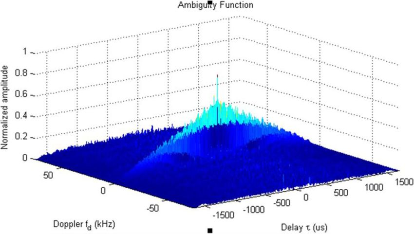
Alotaibi EURASIP Journal on Advances in Signal Processing   (2021) 2021:8                                          Page 4 of 19

                  and non-linear pulse compression method. In linear frequency pulse compression tech-
                  nique, the linear frequency-modulated signal is used as a transmitting signal. This tech-
                  nique is simple, but jamming of the signal is incorporated with it. Non-linear frequency
                  pulse compression technique and the non-linear frequency-modulated signal are used
                  as a transmitting signal. It requires no amplitude weighing of the signal but has system
                  complexities.
                    In phase modulation, the pulse compression technique is a digital method in which
                  the pulse with long duration (tr) is subdivided into short-duration pulses (ts). The pulse
                  compression ratio is given as tr/ts. Bi-phase or polyphase codes can be used in this tech-
                  nique. In bi-phase coding, the phases chosen are 0 or 180°, and in the polyphase code
                  sequence, the phase can be varied from 0 to 360°. However, the poly-phase sequences
                  are susceptible to the Doppler shift.

                  3.0.0.1 Ambiguity function It is the perfect value of the enclosure at the match filter
                  output when the input signal to the filter is Doppler shifted to that of the signal which
                  was matched by the filter. It can also be defined as the match filter time response for
                  the energy signal, which is finite and is Doppler shifted and delayed when compared to
                  the desired zero value of the filter at the receiver. It is a 3D figure of the amplitude vari-
                  ation in accordance with the Doppler and delay. The major properties of the ambiguity
                  function are as follows:

                     The ambiguity function has its maximum amplitude at the origin
                     The graph exhibits symmetric property to the origin
                     The regular volume of the graph irrespective of different waveforms

                    In this paper, binary phase-coded pulse compression sequences are used as it is a
                  digital technique, unlike the frequency modulation pulse compression which is an ana-
                  log method. The performance of the radar system can be measured by two parameters
                  represented as

                     Peak to side-lobe ratio (PSLR)

                                         Power of side‐lobe peaks
                      PSLR ¼ 10 log10                                                                       ð1Þ
                                           Power of main‐lobe

                    Integrated peak to side-lobe ratio (ISLR)

                                          Power of side‐lobe peaks
                       I SLR ¼ 10 log10                                                                     ð2Þ
                                            Power of main‐lobe

                    The well-known phase code pulse compression is Barker sequences, pseudorandom
                  sequences, Golay sequences, and PTM sequences. These sequences are being com-
                  monly used for side lobe reduction.

                  3.1 Barker sequences
                  Barker code or sequences are the sequence of finite binary digits consisting of − 1 and
                  + 1. The only available lengths of barker sequences are 2, 3, 4, 5, 7, 11, and 13 with the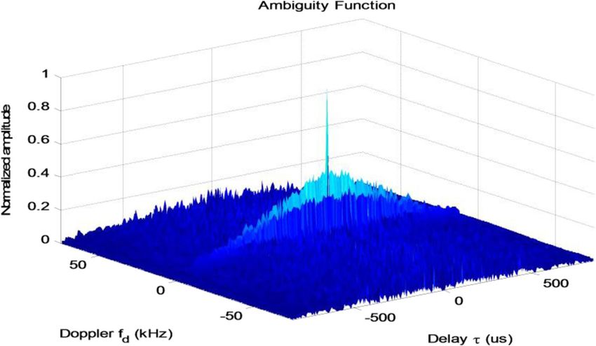
Alotaibi EURASIP Journal on Advances in Signal Processing      (2021) 2021:8                                  Page 5 of 19

                  PSLR of − 6 dB for the sequence length of 2 and − 22 dB for the sequence length of 13.
                  The autocorrelation output of these sequences gives the side lobes with the magnitude
                  of unity, i.e., 1 as presented in Fig. 1. Unfortunately, there are no Barker sequences of
                  more than length 13, which is not suitable in many applications when a higher com-
                  pression ratio is required. To maximize the pulse compression ratio, the codes with
                  greater length are required in many applications. Therefore, the main disadvantage of
                  the Barker sequence is the limited length of the codes.
                    To overcome this issue, compound Barker codes were designed by combining two
                  Barker codes by employing the product of Kronecker. If one code is of length “a1” and
                  the second code is of length “a2”, then the compound Barker code obtained from these
                  two codes is of the length of “a1 a2”. By increasing the length of the code, the pulse
                  compression ratio was improvised, but the side lobes obtained at the output of the
                  matched filter have larger amplitude, unlike the original Barker codes which gave unity
                  amplitude of the side lobes.
                    The ambiguity function of barker sequence has normalized noise amplitude more
                  than 0.5 (see Fig. 2) and is distributed over a wide range of Doppler frequencies. This
                  shadow of one target can mask the other targets present in the background and remain
                  undetectable when Barker code is employed.

                  3.2 Pseudorandom sequences
                  These codes are obtained using modulo-2 adder, shift registers, and a feedback loop.
                  There are 2m possible states if the shift register is of m-stage. The maximum sequence
                  length will be of 2m − 1 period. There is a wide scope of obtaining the codes with mini-
                  mum side lobes. However, it consumes a lot of time in figuring out the sequence with
                  good autocorrelation and minimum amplitude of side lobes as it is a trial-and-error
                  method. These codes are generated randomly without any specific method or technique.

                  3.3 Golay sequences
                  Golay code was introduced by Golay [21] to deal with the spectrometry. It is a binary
                  sequence generally used as error-correcting codes in communication systems. These

                    Fig. 1 Barker code with unity side-lobe amplitude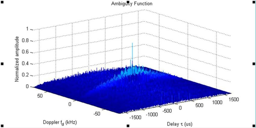
Alotaibi EURASIP Journal on Advances in Signal Processing      (2021) 2021:8                                        Page 6 of 19

                    Fig. 2 Ambiguity function of Barker code (13-bit)

                  codes give zero side lobes as the result of two complementary codes which are added.
                  These two complementary codes were transmitted in a different cycle of pulses, and at
                  the receiver end, they were correlated. When a complementary pair of code is
                  employed, the match filter output of the coefficients which are out of phase and non-
                  periodic sums to “0”. Hence, the side lobes are mitigated at the match filter output. A
                  modified Golay code was also designed to obtain better results at the output of the fil-
                  ter. But these codes were able to detect the targets in a static environment. In the
                  multi-target environment, these codes increase the side lobes of the autocorrelation
                  and degrade the performance of the system.

                  3.4 Prouhet-Thue-Morse (PTM) sequences
                  These codes can be obtained by concatenation of the digit and its complement, and the
                  initial bit can be either “0” or “1”. For example, if we consider “1” as the initial bit, then,
                  2-bit length PTM code will be “1” concatenated with its complement “0”, i.e., “10”.
                     On further complementing, the 4-bit length code obtained is “1001”, the 8-bit code
                  will be 10010110, and so on. Figure 3 presents the autocorrelation of 16-bit PTM se-
                  quence. All the codes generated are of length 2x where x = 0, 1, 2, 3, 4….., and there is
                  no restriction in the length of the code, one can easily generate the sequence to the de-
                  sired length, unlike the barker and Golay sequence.
                     The ambiguity function of PTM sequence is less distributed than that of barker code
                  with same normalized noise amplitude of 0.5 dB (see Fig. 4). It creates only one window
                  (i.e., 10–25 kHz, which is very close to 0.2 dB) that will be helpful to detect the masked
                  targets up to certain Doppler. However, other than these two windows, the noise ampli-
                  tude remains larger which will affect the system performance.
                     In this paper, different binary code sequences have been proposed which not only im-
                  prove the autocorrelation but also enhance the target detection in the presence of Dop-
                  pler. Different codes with various lengths are generated to reduce the side lobes to the
                  desired level of autocorrelation and obtain clear windows to detect the target which is
                  masked in the shadow of slow-moving targets.
Alotaibi EURASIP Journal on Advances in Signal Processing     (2021) 2021:8                                     Page 7 of 19

                    Fig. 3 Autocorrelation of 16-bit PTM sequence

                  3.5 Gold and Kasami sequences
                  A Gold sequence is a binary code used for target detection in a radar system. This se-
                  quence has 2z + 1 code with 2z − 1 period each. “z” is the shift register with linear feed-
                  back used to obtain maximum sequence of length 67. The autocorrelation of the 16-bit
                  length Gold codes obtained in [22] is of noise side lobe of amplitude 18. In Kasami

                    Fig. 4 Ambiguity function of 16-bit PTM sequence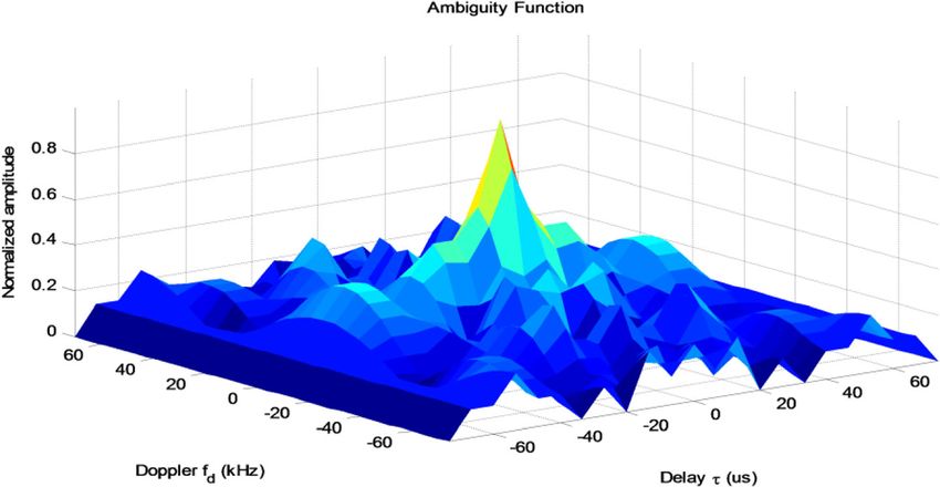
Alotaibi EURASIP Journal on Advances in Signal Processing   (2021) 2021:8                                               Page 8 of 19

                  sequence, the sequence with maximum length is I (g) where g = 1,….2G−1. The se-
                  quences with maximum length are periodic with the period of 2G− 1. The Kasami code
                  of length 64-bit in [23] has the autocorrelation side lobe value as 15.

                  4 Proposed approach
                  Table 1 presents the abbreviations and their description used in this paper. In this sec-
                  tion, digital binary codes are generated using linear block codes (LBC (7, 4)) used to
                  generate the series of digital codes that are tested in this paper in which optimal results
                  are obtained when compared to the standard codes. LBC reduces the mathematical cal-
                  culation and hardware as these codes are already being used in communication systems
                  which in-turn reduces the delay. Reduction in delay enhances the target detection in
                  multi-object ambience by creating clear windows in presence of noise.

                  4.1 Generation of (7, 4) code
                  To generate 7-bit digital code, 4-bit input binary code ICj is required where j = 24 (i.e., j
                  = 0, 1, …, 15 in decimal and 0000, 0001, 0010, …. 1111 in binary number system re-
                  spectively). These input codes are multiplied to the generator matrix using mod 2 addi-
                  tions. The generator matrix GM is represented as

                               0         1
                                 1000111
                               B 0100110 C
                         GM   ¼B         C
                               @ 0010101 A                                                                        ð3Þ
                                 0001011

                   For linear block codes, the generator matrix is pre-defined. The dimensions of this
                  matrix depend on the length of the linear block code (m, n) (here (m, n) = (7, 4)).
                   The final 7-bit code FCj can be represented as

                         F Cj ¼ I Cj  GM                                                                         ð4Þ

                        For example, when j = 0
                        IC0= 0000 then

                         F CO ¼ I CO  GM

                  Table 1 Abbreviations
                  Symbols                                                            Description
                  Pdt                                                                Transmitter pulse duration
                  Prt                                                                Receiver pulse duration
                  tr                                                                 Pulse with long duration
                  ts                                                                 Pulse with short duration
                  PSLR                                                               Peak side-lobe ratio
                  ISLR                                                               Integrated peak side-lobe ratio
                  SNR                                                                Signal to noise ratio
                  Rr                                                                 Side noise reduction ratio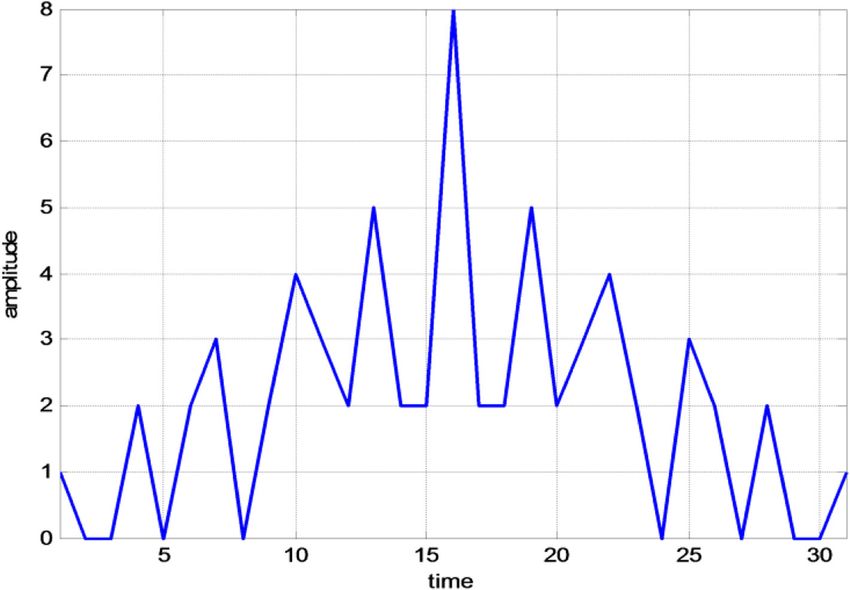
Alotaibi EURASIP Journal on Advances in Signal Processing   (2021) 2021:8                                              Page 9 of 19

                                         0       1
                                         1000111
                                       B 0100110 C
                         →½0 0 0 0 ¼ B         C
                                       @ 0010101 A
                                         0001011

                         F CO ¼ 0 0 0 0 0 0 0

                        when j = 1, IC1= 0001 then
                                            0         1
                                              1000111
                                            B 0100110 C
                         F C1 ¼ ½0 0 0 1  B         C
                                            @ 0010101 A
                                              0001011

                         F C1 ¼ 0 0 0 1 0 1 1

                    In similar manner, the rest of the codes are obtained and are presented in Table 2.
                    The proposed technique follows an algorithm to obtain Doppler tolerant and im-
                  proved autocorrelation property with the help of (7, 4) codes generated and can be rep-
                  resented as.

                        Step 1: Append even or odd parity bit to the 7-bit code FCj to make it a standard code
                        (see Table 3).
                        Step 2: Residue of 7 is used to get the good results as it follows the orthogonality
                        property and covers maximum changes (as it is an odd number and is close to the
                        given 8 bit code). The residue bits can be changed as per the following rule to get the
                        good autocorrelation and optimum value of the side noise.
                        Only 1’s are complemented, and no change is made to 0’s of the code at residue
                        positions (i.e., 1-, 2-, and 4-bit positions)

                  Table 2 Generated codes
                  ICj                                                                           FCj= ICj × GM
                  IC0= 0 0 0 0                                                                  FC0 = 0 0 0 0 0 0 0
                  IC1= 0 0 0 1                                                                  FC1 = 0 0 0 1 0 1 1
                  IC2= 0 0 1 0                                                                  FC2 = 0 0 1 0 1 0 1
                  IC3= 0 0 1 1                                                                  FC3 = 0 0 1 1 1 1 0
                  IC4= 0 1 0 0                                                                  FC4= 0 1 0 0 1 1 0
                  IC5= 0 1 0 1                                                                  FC5 = 0 1 0 1 1 0 1
                  IC6= 0 1 1 0                                                                  FC6 = 0 1 1 0 0 1 1
                  IC7= 0 1 1 1                                                                  FC7 = 0 1 1 1 0 0 0
                  IC8= 1 0 0 0                                                                  FC8= 1 0 0 0 1 1 1
                  IC9= 1 0 0 1                                                                  FC9 = 1 0 0 1 1 0 0
                  IC10= 1 0 1 0                                                                 FC10 = 1 0 1 0 0 1 0
                  IC11= 1 0 1 1                                                                 FC11 = 1 0 1 1 0 0 1
                  IC12= 1 1 0 0                                                                 FC12= 1 1 0 0 0 0 1
                  IC13= 1 1 0 1                                                                 FC13= 1 1 0 1 0 1 0
                  IC14= 1 1 1 0                                                                 FC14 = 1 1 1 0 1 0 0
                  IC15= 1 1 1 1                                                                 FC15 = 1 1 1 1 1 1 1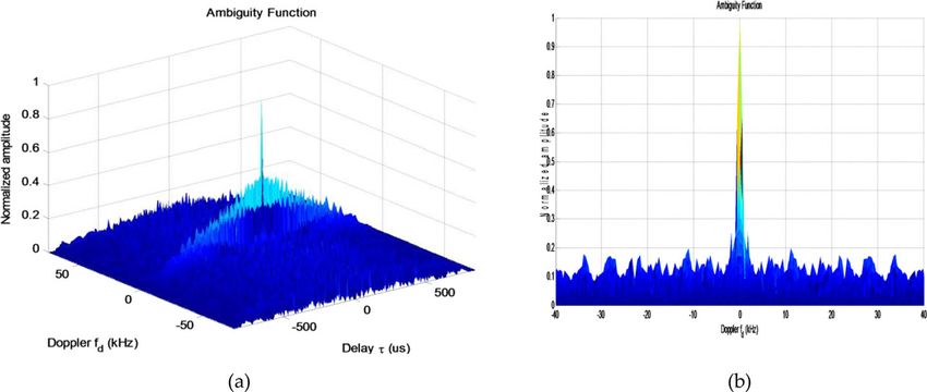
Alotaibi EURASIP Journal on Advances in Signal Processing   (2021) 2021:8                                            Page 10 of 19

                  Table 3 Generated codes with odd parity
                  FCj codes                                  Odd parity bit                FOCj codes
                  FC0 = 0 0 0 0 0 0 0                        1                             FOC0 = 0 0 0 0 0 0 0 1
                  FC1 = 0 0 0 1 0 1 1                        0                             FOC1 = 0 0 0 1 0 1 1 0
                  FC2 = 0 0 1 0 1 0 1                        0                             FOC2 = 0 0 1 0 1 0 1 0
                  FC3 = 0 0 1 1 1 1 0                        1                             FOC3 = 0 0 1 1 1 1 0 1
                  FC4= 0 1 0 0 1 1 0                         0                             FOC4= 0 1 0 0 1 1 0 0
                  FC5 = 0 1 0 1 1 0 1                        1                             FOC5 = 0 1 0 1 1 0 1 1
                  FC6 = 0 1 1 0 0 1 1                        1                             FOC6 = 0 1 1 0 0 1 1 1
                  FC7 = 0 1 1 1 0 0 0                        0                             FOC7 = 0 1 1 1 0 0 0 0
                  FC8= 1 0 0 0 1 1 1                         1                             FOC8= 1 0 0 0 1 1 1 1
                  FC9 = 1 0 0 1 1 0 0                        0                             FOC9 = 1 0 0 1 1 0 0 0
                  FC10 = 1 0 1 0 0 1 0                       0                             FOC10 = 1 0 1 0 0 1 0 0
                  FC11 = 1 0 1 1 0 0 1                       1                             FOC11 = 1 0 1 1 0 0 1 1
                  FC12= 1 1 0 0 0 0 1                        0                             FOC12= 1 1 0 0 0 0 1 0
                  FC13= 1 1 0 1 0 1 0                        1                             FOC13= 1 1 0 1 0 1 0 1
                  FC14 = 1 1 1 0 1 0 0                       1                             FOC14 = 1 1 1 0 1 0 0 1
                  FC15 = 1 1 1 1 1 1 1                       0                             FOC15 = 1 1 1 1 1 1 1 0

                    Only 0’s are complemented, and no change is made to 1’s of the code at residue
                    positions
                    Both 1’s and 0’s are complemented of the code at residue positions

                    The quadratic residue is defined as, if there is an integer “0 < x < p”, such that

                      2 ¼ qð modpÞ:                                                                          ð5Þ

                    Then, “q” is said to be a quadratic residue (mod p)

                    Step 3: The resultant codes are concatenated to generate the digital codes with the
                    lengths of 128 and 256 (as the recent research considers the codes of these lengths).
                    Step 4: Auto-correlation property of the obtained codes is tested.

                    The 0’s in the code are replaced with − 1’s so as to get the amplitude value equal to
                  the length of the code.

                    Step 5: Doppler tolerance of the codes are tested; in this test, no changes are made to
                    the codes obtained.

                    In the proposed approach, odd parity (step 1) is appended to the FCj codes, and the
                  resultant codes FOCj are presented in Table 3.
                    Now considering step 2, Tables 4 and 5 depict all the three cases of this step.
                    To improve the signal-to-noise ratio (SNR) and autocorrelation property of the re-
                  ceived echo signal, the length of the linear block code is increased. Here, digital codes
                  of lengths 128 and 256 bits are designed and tested.
Alotaibi EURASIP Journal on Advances in Signal Processing (2021) 2021:8 Page 11 of 19
Table 4 Generation of codes (Pj) as per step 2, case 1
FOCj codes Only 1’s are complemented at residue positions (P1, P2, and P4)
Pj P1 P2 P3 P4 P5 P6 P7 P8
FOC0 = 0 0 0 0 0 0 0 1 P0 0 0 0 0 0 0 0 1
FOC1 = 0 0 0 1 0 1 1 0 P1 0 0 0 0 0 1 1 0
FOC2 = 0 0 1 0 1 0 1 0 P2 0 0 1 0 1 0 1 0
FOC3 = 0 0 1 1 1 1 0 1 P3 0 0 1 0 1 1 0 1
FOC4= 0 1 0 0 1 1 0 0 P4 0 0 0 0 1 1 0 0
FOC5 = 0 1 0 1 1 0 1 1 P5 0 1 0 1 1 0 1 1
FOC6 = 0 1 1 0 0 1 1 1 P6 0 0 1 0 0 1 1 1
FOC7 = 0 1 1 1 0 0 0 0 P7 0 0 1 0 0 0 0 0
FOC8= 1 0 0 0 1 1 1 1 P8 0 0 0 0 1 1 1 1
FOC9 = 1 0 0 1 1 0 0 0 P9 0 0 0 0 1 0 0 0
FOC10 = 1 0 1 0 0 1 0 0 P10 0 0 1 0 0 1 0 0
FOC11 = 1 0 1 1 0 0 1 1 P11 0 0 1 0 0 0 1 1
FOC12= 1 1 0 0 0 0 1 0 P12 0 0 0 0 0 0 1 0
FOC13= 1 1 0 1 0 1 0 1 P13 0 0 0 0 0 1 0 1
FOC14 = 1 1 1 0 1 0 0 1 P14 0 0 1 0 1 0 0 1
FOC15 = 1 1 1 1 1 1 1 0 P15 0 0 1 0 1 1 1 0
Table 5 Generation of codes (Qj and Rj) as per step 2, cases 2 and 3
Only 0’s are complemented at residue Both 1’s and 0’s are complemented at residue
positions (Qj) positions (Rj)
Q0= 1 1 0 1 0 0 0 1 R0= 1 1 0 1 0 0 0 1
Q1= 1 1 0 1 0 1 1 0 R1= 1 1 0 0 0 1 1 0
Q2= 1 1 1 1 1 0 1 0 R2= 1 1 1 1 1 0 1 0
Q3= 1 1 1 1 1 1 0 1 R3= 1 1 1 0 1 1 0 1
Q4= 1 1 0 1 1 1 0 0 R4= 1 0 0 1 1 1 0 0
Q5= 1 1 0 1 1 0 1 1 R5= 1 0 0 0 1 0 1 1
Q6= 1 1 1 1 0 1 1 1 R6= 1 0 1 1 0 1 1 1
Q7= 1 1 1 1 0 0 0 0 R7= 1 0 1 0 0 0 0 0
Q8= 1 1 0 1 1 1 1 1 R8= 0 1 0 1 1 1 1 1
Q9= 1 1 0 1 1 0 0 0 R9= 0 1 0 0 1 0 0 0
Q10= 1 1 1 1 0 1 0 0 R10= 0 1 1 1 0 1 0 0
Q11= 1 1 1 1 0 1 0 0 R11= 0 1 1 0 0 0 1 1
Q12= 1 1 0 1 0 0 1 0 R12= 0 0 0 1 0 0 1 0
Q13= 1 1 0 1 0 1 0 1 R13= 0 0 0 0 0 1 0 1
Q14= 1 1 1 1 1 0 0 1 R14= 0 0 1 1 1 0 0 1
Q15= 1 1 1 1 1 1 1 0 R15= 0 0 1 0 1 1 1 0Alotaibi EURASIP Journal on Advances in Signal Processing (2021) 2021:8 Page 12 of 19
Fig. 5 Autocorrelation function of fC1
4.2 Generation of 128-bit digital code
Concatenation of codes is performed to obtain the digital code of length 128. Consider-
ing the 16 FOCj codes, each of length of 8-bit gives 128-bit (16×8) code (fCj) when
concatenated row wise represented as
f c1 ¼ F OC0 F OC1 F OC2 F OC15 ð6Þ
Now, the code fC1 is 128-bit code and is tested for the property of autocorrelation
and Doppler tolerance (ambiguity) presented in Figs. 5 and 6 a and b. Figure 6 b is a 2-
dimensional view of Fig. 6a in which the clear windows can be seen.
In Fig. 5, the side noise value of the code (fC1) is 13, and the amplitude of the main
lobe is 128. The reduction ratio (Rr) of side noise can be calculated as
Fig. 6 a Doppler tolerance of fC1. b Amplitude v/s Doppler of fC1Alotaibi EURASIP Journal on Advances in Signal Processing (2021) 2021:8 Page 13 of 19
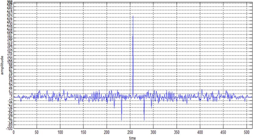
Fig. 7 Autocorrelation function of fC2
maximum amplitude of side noise
Rr ¼ 20 log10 ð7Þ
amplitude of main lobe
Thus, Rr of fC1 given as
13
Rr ð f c1 Þ ¼ 20 log10 ¼ − 19:87 dB
128
From Fig. 6 b, it has been observed that the side noise is either of amplitude 0.2 or
less than 0.2, which is the standard value of noise lobe [17, 18]. There exist almost clear
Fig. 8 Doppler tolerance of fc2Alotaibi EURASIP Journal on Advances in Signal Processing (2021) 2021:8 Page 14 of 19
Table 6 The Rr (fC3) and Rr (fC4) and their clear windows
Code Rr values in dB Clear windows in KHz
fC3 − 11.51 3–11, 14–16, 19–22, 24–40
fC4 − 10.10 2–16, 19–40
windows from frequencies 2 to 40 kHz. So any moving or static object can be detected
easily as it cannot mask itself.
Now consider the code fC2 which can be obtain by concatenation of Rj codes row
wise and can be represented as
f c2 ¼ R0 R1 R15 ð8Þ
The autocorrelation function of fC2 is presented in Fig. 7 with the side noise ampli-
tude value as 8 and main lobe value is 128. The Rr (fC2) = − 24.08 dB. Figure 8 presents
the Doppler tolerance of the code fC2 with the side noise of amplitude 0.2. From Fig. 8,
it is observed that clear windows are from 2 to 40 kHz.
In similar fashion, the codes fC3 and fC4 are tested for autocorrelation function and
Doppler tolerance where
fC3= concatenation of Pj codes (row wise) and can be given as
f C3 ¼ P 0 P1 P2 P 15 ð9Þ
fC4= concatenation of Qj codes (row wise) and can be given as
f C4 ¼ Q0 Q1 Q2 Q15 ð10Þ
The Rr (fC3) and Rr (fC4) and their clear windows are presented in Table 6.
4.3 Generation of 256-bit digital code
These codes are obtained by concatenation of FOCj with Pj or Qj or Rj such that
f C5 ¼ F OC0 P 0 F OC1 F OC15 P 15 ð11Þ
f C6 ¼ F OC0 Q0 F OC1 Q1 F OC15 Q15 ð12Þ
Fig. 9 Autocorrelation function of fC5Alotaibi EURASIP Journal on Advances in Signal Processing (2021) 2021:8 Page 15 of 19
Fig. 10 Doppler tolerance of fC5
f C7 ¼ F OC0 R0 F OC1 R1 F OC15 R15 ð13Þ
The autocorrelation and Doppler tolerance of these codes are shown in Figs. 9, 10,
11, 12, 13, and 14.
Table 7 presents the Rr (fC5), Rr (fC6), Rr (fC7), and their clear windows.
From the above results, it is evident that code fC2 and fC7 of lengths 128 and 256 re-
spectively gives better results when compared to the other codes obtained.
5 Results and discussion
Multiple radar systems use many antennas for communication and target detection.
Interference between any two radar signals should be minimized to detect the static as
Fig. 11 Autocorrelation function of fC6Alotaibi EURASIP Journal on Advances in Signal Processing (2021) 2021:8 Page 16 of 19
Fig. 12 Doppler tolerance of fC6
well as moving target precisely; therefore, the sequences used must have better autocor-
relation and Doppler tolerance.
Simulation results (shown in Table 8) depict that the designed binary sequences show
improvised autocorrelation properties when compared to the existing techniques such
as Barker codes, Golay codes, PTM, and over-sampled PTM (discussed in Section 3).
The Kasami and Gold codes in [22, 23] are compared with the proposed binary codes.
The proposed code gives better autocorrelation response when compared with Kasami
and Gold codes which are commonly used to reduce side lobes in radar target detec-
tion process and are also applicable to static objects only. For moving object detection,
the Doppler tolerance of the proposed codes is compared with [17, 18]. The proposed
approach gives large clear windows when compared with the existing methods. The
Fig. 13 Autocorrelation function of fC7Alotaibi EURASIP Journal on Advances in Signal Processing (2021) 2021:8 Page 17 of 19
Fig. 14 Doppler tolerance of fC7
length of the codes is not limited; one can design the sequence up-to-the desired length
by using mathematical operations. The designed sequences have optimal side noise,
and different clear windows have been obtained with respect to different Doppler.
These windows can be used to detect the moving targets with respect to the desired
Doppler. In the detection process, a matched filter is used, and the step of the range
gate can be mitigated which reduces the hardware. Hence, using four A-scope or PPI
(plan position indicator) units (receiver devises) for different sequences (i.e., of 128-
and 256-bit length) will cover the entire range of Doppler shift as a result of which no
target in the multi-target environment is missed. Hence, the designed sequences can be
used for multiple radar systems to communicate and detect the targets (both static and
moving) with high resolution, improvised range, precise target detection, and minimum
interference.
6 Conclusion
The presented codes are easy to implement and useful to detect stationary and moving
objects together with enhanced autocorrelation characteristics in the presence of Dop-
pler. The proposed series of codes have a distinctive benefit against the state-of-the-art
(i.e., PTM, Barker, over-sampled PTM, Golay, Gold codes and Kasami) that every code
follows orthogonality principle to decrease the numerical complication. These codes
can be obtained from linear block code by amending arithmetic and information
Table 7 Rr (fC5), Rr (fC6), Rr (fC7), and their clear windows
Code Rr values in dB Clear windows in KHz
fC5 − 16.57 1–40
fC6 − 16.57 1–40
fC7 − 21.72 1–40Alotaibi EURASIP Journal on Advances in Signal Processing (2021) 2021:8 Page 18 of 19
Table 8 Rr values and clear windows of the codes obtained
Code Rr values in dB Clear windows in kHz
fC1 − 19.87 2–40
fC2 − 24.08 2–40
fC3 − 11.51 3–11, 14–16, 19–22, 24–40
fC4 − 10.10 2–16, 19–40
fC5 − 16.57 1–40
fC6 − 16.57 1–40
fC7 − 21.72 1–40
theory. These codes reduce one step of target recognition (i.e., range gates) which re-
duces the delay and price of the equipment. The designed codes are well suitable to
sense multiple moving and fast objects on top of MAC-3, i.e., 5th generation combatant
vehicles. Multiple clear windows are created by using the designed codes with noise
amplitudes reduced to 0.2 dB (which is the standard threshold limit).
Acknowledgements
Not applicable.
About the Authors
Majid Alotaibi received his Ph.D. from The University of Queensland, Brisbane, Australia, in 2011. Currently, he is an
associate professor with the Department of Computer Engineering, Umm Al-Qura University, Makkah, Saudi Arabia. He
is a Co-founder of the SMarT Lab. His current research interests include mobile computing, Networks: mobile and sen-
sor networks, and computer networks, Internet of Things (IoT): wireless technologies, IoT in Healthcare, Smart Cities,
and RFID, Communications: antennas and propagation, protocols, and radar.
Declaration
The research work is implemented, and the experiment is carried out.
Author’s contributions
The digital codes using linear block coding technique has been designed and tested to improve the signal-to-noise ra-
tio and create multiple windows with respect to different Doppler to get the clear information about static and mul-
tiple targets. The author read and approved the final manuscript.
Funding
Not applicable.
Availability of data and materials
Not applicable.
Competing interests
The author declared that there is no conflict of interest.
Received: 13 September 2020 Accepted: 29 December 2020
References
1. P. Addabbo, A. Aubry, A. De Maio, L. Pallotta, S.L. Ullo, HRR profile estimation using SLIM. IET Radar, Sonar Navigation
13(4), 512–521 (2019)
2. Aubry, A., Carotenuto, V., De Maio, A., et al.: ‘High range resolution profile estimation via a cognitive stepped frequency
technique’. IEEE Trans. Aerosp. Electron. Syst 55(1), 444–458 (2018). https://doi.org/10.1109/TAES.2018.2880024
3. N. Levanon, Mitigating range ambiguity in high PRF radar using inter-pulse binary coding. IEEE Transact. Aerosp.
Electron. Syst 45(2), 687–697 (2009). https://doi.org/10.1109/TAES.2009.5089550
4. S. Shi, Z. Zhao, J. Liu, Comparison of radar waveforms combining pseudo-random binary phase coding and chirp
modulation for an high-frequency monostatic radar. IET Radar, Sonar Navigation 10(5), 935–944 (2016). https://doi.org/
10.1049/iet-rsn.2014.0507
5. R. Tian, G. Zhang, R. Zhou, W. Dong, Detection of polyphase codes radar signals in low SNR. Math. Probl. Eng. 2016, 1–6
(2016). https://doi.org/10.1155/2016/1382960
6. F.F. Kretschmer, B.L. Lewis, Doppler properties of polyphase coded pulse-compression waveforms. IEEE Trans. Aerosp.
Electron. Syst. AES-19(4), 521–531 (1983)
7. R. Sivaswami, Self-clutter cancellation and ambiguity properties of sub complementary sequences. IEEE Trans. Aerosp.
Electron. Syst. AES-18(2), 163–181 (1982)Alotaibi EURASIP Journal on Advances in Signal Processing (2021) 2021:8 Page 19 of 19
8. J.-H. Guey, M.R. Bell, Diversity waveform sets for delay-Doppler imaging. IEEE Trans. Inform. Theory 44(4), 1504–1522
(1998)
9. G.E. Coxson, W. Haloupek, Construction of complementary code matrices for waveform design. IEEE Transactions on
Aerospace and Electronic Systems 49(3), 1806–1816 (2013). https://doi.org/10.1109/taes.2013.6558021
10. C.-F. Chang, M.R. Bell, Frequency-coded waveforms for enhanced delay-Doppler resolution. IEEE Transact. Information
Theory 49(11), 2960–2971 (2003). https://doi.org/10.1109/tit.2003.818408
11. H. Deng, Poly-phase code design for orthogonal netted radar systems. IEEE Transactions on Signal Processing 52(11),
3126–3135 (2004). https://doi.org/10.1109/tsp.2004.836530
12. A. Pezeshki, R. Calderbank, L.L. Scharf, Sidelobe suppression in a desired range/Doppler interval (IEEE Radar conference
2009 at Pasadena, CA, 2009), pp. 1–5
13. H. Deng, Synthesis of binary sequences with good autocorrelation and cross-correlation properties by simulated
annealing. IEEE Trans. Aerosp. Electron. Syst. 32, 98–107 (1996)
14. Gladkova, I., & Chebanov, D.. Suppression of grating lobes in stepped-frequency train. IEEE International Radar
Conference, 2005, pp. 371–376
15. N. Levanon, E. Mozeson, Nullifying ACF grating lobes in stepped-frequency train of LFM pulses. IEEE Trans. Aerosp.
Electron. Syst. 39(2), 694–703 (2003)
16. J.D. Jenshak, J.M. Stils, “A fast method for designing optimal transmit codes for radar” IEEE Radar Conference (2008), pp.
1038–1042 26-30 May 2008
17. M. Alotaibi, in International Conference on Communications and Cyber Physical Engineering, Lecture Notes in Electrical
Engineering. Improved target detection in Doppler tolerant radar using a modified hex coding technique (Springer,
Singapore, 2018), pp. 63–72
18. M. Aleem, R.P. Singh, S.J. Ahmad, in Innovations in Electronics and communication engineering, Lecturer Notes in Networks
and Systems Vol 33. Enhance multiple moving target detection in Doppler tolerant radar using IRAESC technique
(Springer, Singapore, 2019), pp. 417–426
19. C.G. Raghavendra, N. Harsha, S. Mohan Kumar, H.S. Prashantha, Joint reduction of PMEPR and sidelobe in multicarrier
radar signals using ZC and SC method. WSEAS Trans. Commun. 19, 9–17 (2020)
20. N. AdithyaValli, D. Elizabath Rani, C. Kavitha, Convolution windows for side lobe reduction. Int. J. Innov. Technol.
Exploring Eng. 8(10), 3526–3529 (2019)
21. M.J.E. Golay, Complementary series (1961). IRE Trans. Inform. Theory 7(2), 82–87 (1961)
22. A. Khatter, P. Goyal, Design and analyze the various m-sequences codes in MATLAB. Int. J. Emerg. Technol. Adv. Eng.,
ISSN 2250-2459 2(11) (2012)
23. I.G.A.G.K. NyomanPramaita, D.H. Diafari, D.N.K.P. Negara, A. Dharma, New orthogonal small set Kasami code sequence.
Majalah Ilmiah Teknologi Elektro 14(1) (2015). https://doi.org/10.24843/mite.2015.v14i01p10
Publisher’s Note
Springer Nature remains neutral with regard to jurisdictional claims in published maps and institutional affiliations.You can also read