What's New in Autodesk Inventor 2019 - CAD Studio
←
→
Page content transcription
If your browser does not render page correctly, please read the page content below
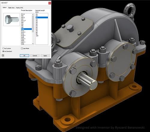
What's New in Autodesk Inventor 2019
Inventor 2019 is built for today's engineering and design professional.

Inventor customers from around the world continue to provide feedback and drive
enhancements to the Inventor 2019 experience. This release marks a continued focus on
improved performance, automation and core modeling workflows that enable professional-
grade mechanical engineering design. Inventor 2019 also connects to the Autodesk cloud to
unlock collaboration, design and supply chain user workflows.

Design and engineering professionals work to deliver innovation and high-quality products
every day. Inventor 2019 delivers with professional grade improvements in design, automation,
and performance to stay ahead of market demands.

Assembly and Drawing Performance
We know performance is important, so we're constantly looking for ways to improve Inventor
performance. This release has improvements in the following areas:

1. Assembly
   1. In-place editing
   2. Updates
   3. Pattern selection
2. Drawing
   1. View creation
   2. Updates
   3. Navigation
Content Center
In-memory caching

To reduce your time waiting for remotely hosted content to display, Inventor Content Center
now caches the remote content during the session. When content is accessed, the initial
content is cached for subsequent use eliminating the need to make the remote request again in
that session. When the Inventor session concludes, the cache is cleared.
iLogic
Components and Management Behavior

iLogic improvements make it easier to create rule code for adding, modifying, and deleting
components and constraints.

Document Units Geometry

There are new functions that use document units for coordinate values and objects
representing points, vectors, and matrices.
New iLogic Assembly Add Constraints Functions

The new iLogic Relationships (Add) functions allow you to create an iLogic assembly whose
occurrences and constraints are generated by a rule.
New Capture Current State Commands

The Capture Current State command now retains states when you use: Components.Add,
Components Constraints.Add, Constraints.Add, and Patterns.Add.

Constrain Geometry by Assigned Names

You can now assign names to faces and edges, and then create a rule that adds the
constraint(s) directly to a face or edge with those names.
iLogic Help for Functions

Help for iLogic functions and arguments are now available from the iLogic API Reference help
node. This help content is in English only.

Model-Based Definition
The Tolerance Advisor now displays constraint state using a color code. Click Face Status
Coloring in the Tolerance Advisor to turn on the display of colors.
Inventor 2019 connects to the Autodesk Cloud to allow users to collaborate, design and
communicate their designs in new and powerful ways. A cloud connected Inventor enables you
to leverage their design beyond the desktop with simple, secure, and powerful workflows.
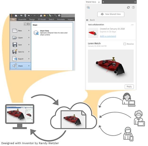
Shared Views
A subscription benefit
Shared Views provide a better way for designers, engineers, and visual artists to get feedback
on their work in progress, simplifying and speeding up review cycles. Use Shared Views to share
2D or 3D views of your work online and see comments directly in the product you're working in.
With shared views, any reviewer can review and comment online via the Autodesk Viewer.
They avoid the need for stakeholders to install a specific viewer and provide powerful
commenting and markup tools for conveying detailed feedback. Because shared views are
visual representations that expire after 30 days, your native designs or models are always
protected. This gives their authors a way of clearly separating unfinished work being shared for
feedback purposes from more formal and permanent deliverables.
Shared views enable users to:
• Quickly create online visual representations from within desktop application.
• Generate a link that can be shared with any stakeholder.
• Stakeholders can view the shared view and add comments and mark-up via Autodesk
Viewer.
• Authors can review comments and see feedback they've received within the authoring
application, then respond.
Autodesk Drive
A subscription benefit

Autodesk Drive is a cloud storage solution that allows individuals and small teams to organize,
preview, and share any type of design data. Autodesk Drive can be accessed directly from
desktop applications with Desktop Connector.

Desktop Connector for Autodesk Drive
Desktop Connector is a desktop service that integrates an Autodesk data management source
(or data source) with your desktop folder and file structure for easy file management.

AnyCAD for Fusion 360
Move Data Between the Desktop and the Cloud for Fusion 360 is available as a Preview in
Inventor 2019. This Preview allows you to experience new features on a test-only basis within
Inventor before these features are fully released.
This new AnyCAD workflow allows you to take advantage of the power of Inventor and Fusion
360 together.
Overview

Inventor continues to expand AnyCAD functionality by adding support for Fusion 360 design
files.

Bring Fusion 360 models directly into Inventor for system integration, large assembly design,
and documentation. When the Fusion 360 design is updated, the changes can be consumed in
Inventor.

Similarly, you can reference Inventor parts into Fusion 360 for cloud-enabled simulation, CAM,
and more. Because Fusion 360 now uses the same AnyCAD technology, changes in the Inventor
model can be automatically consumed in Fusion 360.

AnyCAD gives you the flexibility to use Inventor’s world class 3D mechanical engineering design
capabilities with the Product Innovation Platform, giving you the power to make anything.
Getting Started
To share data between Inventor, a desktop application, and Fusion 360, a cloud based platform,
there are a few things to set up and consider.
1. Install Desktop Connector. This piece enables you to move data between the desktop and
the cloud. Desktop Connector installs a desktop folder that provides direct access to Fusion
Team cloud space .
Download the Desktop Connector installer from your profile menu in your Fusion Team
account.
2. Identify a Fusion Team account to use for sharing data. Fusion Team provides a personal
central workspace in a cloud hub for your projects.
Import Fusion 360 (.fusiondesign) files as an AnyCAD Reference Model
Once set up, you can open/import Fusion 360 (.fusiondesign) files from your Fusion 360 drive
with an option to convert or create an AnyCAD reference. Importing a Fusion
360 (.fusiondesign) file as an AnyCAD reference model maintains a link to the selected file
which enables you to monitor and update as the model changes. This workflow allows you to
use Inventor data in Fusion 360 and Fusion 360 data in Inventor, allowing more flexible use of
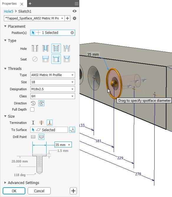
these tools as part of their product design and manufacturing process.Customer focused enhancements can be seen throughout Inventor 2019. Improving commands, streamlining workflows, and refreshing existing tools are areas where feedback from our customers around the world continue to improve the Inventor user experience. Many of the following enhancements were implemented directly from feedback posted on Inventor Ideas and direct customer engagements. Hole Command The new Hole command is faster and smarter by inferring hole placement from your interactions. You can apply dimensional and concentric constraints without first creating a sketch. Then, switch between feature editing and sketch editing without exiting the command.
Sheet Metal Face and Corner Enhancements
Symmetric Face

  An Inventor® Ideas submission

Many have asked to be able to center the sheet metal part along its thickness. We heard you,
and the Face command now supports extruding from the mid-plane to create a symmetric face.

Laser Weld Relief Shape

 The Linear Weld corner relief terminates on a point, the Arc Weld corner relief shape
terminates with a straight line segment. The new Laser Weld corner relief terminates with a
tangent arc and is more suitable for laser cut parts.
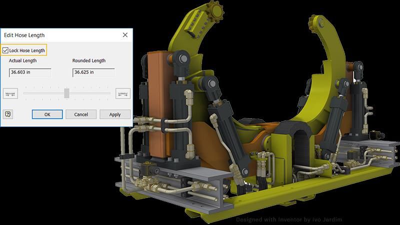
Tube and Pipe
Lock Hose Length

  An Inventor® Ideas submission

 The new option, Lock Hose Length, allows you to calculate an exact sum of hose length. When
selected, if components move or shift, this option prevents the length of the hose from
changing due to adaptivity.

You can also lock hose length by adding a General Dimension        from the 3D Sketch tab
Constraints panel to a flexible hose in the graphics window.
Frame Generator
CUTDETAIL Enhancement

  An Inventor® Ideas submission

 The values generated by applying the Trim/Extend command to cut angles on frame members
are available in the iProperties/Custom tab as CUTDETAIL1, CUTDETAIL2, etc. These can be
included in the Bill of Materials and Parts List. Additionally, the Frame Generator G_L
parameter reports the correct lengths.
Sketch Enhancements
The Helical Curve command has been enhanced to streamline creating a variable pitch helix.

 For drawing sketches, Autoproject edges during curve creation has been improved to behave
the same as model sketches.
Inverted Fillet
  An Inventor® Ideas submission

This new fillet option is the result of your feedback. You can create a fillet with 1) convex edges
or 2) concave edges.

Direct Edit Supports Automatic Blending
 Previously with 3D Model tab Modify panel Direct Edit, you could only rotate or move a face
feature to another location. When deselected, Automatic Blending maintains this behavior and
moves a face to a new location. When selected, the total length of a face feature is modified.

Automatic blending is a re-blending technology that automatically moves adjacent tangential
faces and also creates new blends if required. It is available when you move or rotate a face.
Thicken Command
  An Inventor® Ideas submission

Information about the depth and the method now display in the browser when the Application
Option/Parts tab Display extended information after feature node name in browser setting is
enabled.

Assembly Constraints
New Solutions for Constraining 2 Axes

  An Inventor® Ideas submission

The Place Constraint dialog box provides 3 new solutions for constraining 2 axes. When you
select 2 axes you can use the new options, Opposed and Aligned, to control the axis direction
when creating a mate constraint, making it easier for you to get the axes positioned the way
you want.
1. Opposed (default): Reverses the mate direction of the first selected component.
2. Aligned: Maintains the mate direction of the first selected component.
3. Undirected: Creates an undirected axis constraint on the closest axis.
New Option to Lock Rotation with Insert Constraint

  An Inventor® Ideas submission

Use the new option, Lock Rotation, to lock the rotational degrees of freedom on a component
when placing an insert constraint. This option prevents the part from rotating.

With Lock Rotation applied, the Insert constraint displays with a locked icon in the browser.
Angular Constraint Enhancements

  An Inventor® Ideas submission

 The Directed and Undirected Angle setting within an angular constraint now persist when
creating a new angle constraint or making edits to the existing constraint.

Migrate Custom Settings
 Use Migrate Custom Settings to bring your existing customization and Application Option
settings into the latest Inventor Release. Administrators have additional control over use of this
option in deployments.
Color Schemes
  An Inventor® Ideas submission

The color scheme editor is installed as part of Inventor 2019. You can access it from the
Application Options > Color Tab. Customizations are saved to the Application Options xml file.

Streamlining the Installation Process
 To expedite the installation process, some optional add-ins have been removed from the
installation and are made available by means of a separate download, links included where
applicable. This refinement affects the following add-ins or applications:
1. Autodesk Design Review
2. Vault Basic, available via your Autodesk account and through the Autodesk Desktop
     Application
3. Print Studio
Subscription Benefits Collaborate on 2D and 3D Views with Anyone Using Shared Views Collaborate with Shared Views Use Shared Views to collaborate on a visual representation of your model or design online. Simplify and speed up review cycles. Collaborate on 2D and 3D views with anyone, and receive comments and feedback directly inside your product. Any reviewer can review and comment online. Because shared views are visual representations, your designs or models are always protected. An Autodesk product is not needed to collaborate on shared views. All collaborators can view the shared view and add comments in Autodesk Viewer. Subscribe to Inventor or Inventor LT to use Shared Views. Store and Share your Data in the Cloud Autodesk Drive Autodesk Drive is a cloud storage solution that allows individuals and small teams to organize, preview, and share any type of design data. You can use Autodesk Drive to: 1. Upload data to a personal cloud drive. 2. Organize and manage your data into folders. 3. With Desktop Connector installed, you can view and organize files stored in Drive from your desktop and desktop applications, and only download when you need them. 4. View 2D and 3D designs within the browser on any device. 5. Share your drive with others for viewing, editing, uploading, and managing data. Subscribe to Inventor or Inventor LT to access Autodesk Drive as a subscription benefit. For more information on Autodesk Drive, see Autodesk Drive.
Assembly
 Constraint Enhancements
 New Solutions for Constraining 2 Axes
 The Place Constraint dialog box provides 3 new solutions for constraining 2 axes.

 Use the new options Opposed and Aligned to control the direction of an axis when creating a
 mate constraint between 2 axes. These options make it easier for you to get the axes
 positioned the way you want.

 1. Opposed (default): Reverses the mate direction of the first selected component.
 2. Aligned: Maintains the mate direction of the first selected component.
 3. Undirected: Creates an undirected axis constraint on the closest axis.

The example below displays the                                           With Aligned selected, the direction
center axis of the first selected   With Opposed selected, the           of the axis of the first selected
component, and the center axis      direction of the axis of the first   component is maintained.
of the second selected              selected component is reversed.
component.

   An Inventor® Ideas submission
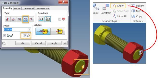
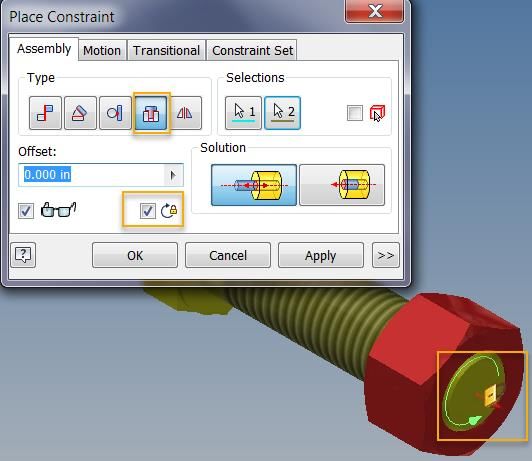
New Option to Lock Rotation with Insert Constraint
 Use the new option, Lock Rotation, to lock the rotational degrees of freedom on a component
 when placing an insert constraint. This option prevents the part from rotating.

A lock icon displays in the graphics window when     To view the lock icon in the graphics window
placing an Insert constraint with Lock Rotation      after closing the dialog box, click Assemble
selected. By default, the lock icon no longer        Relationships panel Show. Once displayed,
displays after closing the Place Constraint dialog   you can right-click the icon, and access
box.                                                 options for suppressing, and other edit
                                                     operations.

 Once Lock Rotation applied, the Insert constraint displays with a locked icon in the browser.

 Rotation is not available when creating an iMate definition. Lock Rotation is only available when
 creating an Insert constraint or editing an iMate result.

   An Inventor® Ideas submission
Angular Constraint Enhancements Previously, a Directed and Undirected Angle constraint flipped when a related component's position changed. Now, the Directed and Undirected Angle setting within a angular constraint persists when creating a new angle constraint or making edits to the existing constraint. An Inventor® Ideas submission Tube and Pipe Enhancements Lock Hose Length Previously, the value in the Actual Length field in the Edit Hose Length dialog box was not a reliable indicator of the length of the flexible hose in an assembly. The new option, Lock Hose Length, allows you to calculate an exact sum of hose length. When selected, if components move or shift, this option prevents the length of the hose from changing due to adaptivity. You can also lock hose length by adding a General Dimension from the 3D sketch tab Constraints panel to a flexible hose in the graphics window. An Inventor® Ideas submission
Content Center/Vault Server Enhancement
If you have custom libraries on a Vault server, you can deselect the new Application Options
setting, Check all Families for Library updates, to quickly suppress all families in custom
libraries from synchronizing to their parent library on the Vault Server.

Previously, the only way to prevent all Content Center families in custom libraries from being
synchronized to their parent families on the Vault Server was to suppress each family
individually in the Content Center editor.

This new option is located on the Application Options Content Center tab.
General Enhancements in Assembly
Browser icons
 Icons in Express and Full mode are being adjusted to align the display between those
environments. The following explains how icons appeared in 2018 and earlier releases and then
shows how these will display from 2019 onward.

Legend

     Express mode, left column;      Full mode, right column

Solid, Surface, and Multi-body Icons in Full Mode

For 2018 and prior releases, in Express mode, solid, surface, and multi-body components were
displayed using the standard part icon. When you switched to Full mode, the icons changed to
display as a solid, surface, or multi-body component.

For 2019 and later, these components display the same browser icon in Full mode as when in
Express mode.
Sheet Metal, iPart, and Content Center Icons in Express Mode
For 2018 and prior releases, in Express mode, Sheet Metal components, Content Center
components, and iParts displayed with the standard part icon.
For 2019 and later, these components display the same icon in Express mode as when in Full
mode.
Express Mode
The ability to resolve files when opening an assembly is now available in Express mode.
Frame Generator CUTDETAIL Enhancement
Previously the values generated by applying the Trim/Extend command to cut angles on frame
members were not available in the iProperties/Custom tab. In addition, the Frame Generator
G_L parameter did not reliably report correct lengths.
These limitations are now resolved. In Inventor 2019:
1. The Frame Generator G_L parameter reliably reports correct lengths.
2. The values generated by applying the Trim/Extend command to cut angles display in the
iProperties/Custom tab as CUTDETAIL1, CUTDETAIL2, etc. and can be included in the Bill of
Materials and Parts List.
Use the Rebuild All command to apply this behavior to models created in earlier versions of
Inventor: Open an assembly file that was created in an earlier version and click Manage tab
Update panel Rebuild All.
An Inventor® Ideas submissionParts Model-Based Definition Enhancements Tolerance Advisor Shows Face Status Coloring Previously, Tolerance Advisor reported only the status of the tolerance scheme. You can now enable Face Status Coloring to display the constraint state on the model. Click Face Status Coloring at the bottom of the Tolerance Advisor browser to turn face coloring on and off. Tip: Check out the Create and Analyze Tolerance Features tutorial in the gallery to experience the new workflow. 3D Annotation Hole/Thread Note Displays Quantity In the previous release, the quantity of a hole pattern was displayed only when you used a Tolerance Feature to annotate the hole. The General Annotation Hole/Thread Note command was updated to display the pattern quantity.
The active style library must contain the 2019 3DA style or the quantity is not displayed. If the
quantity is not displayed after you add the annotation, choose the Manage tab > Update to add
the quantity string to the 3DA styles.

Important: Autodesk added 3DA styles to the default style library to support MBD and 3DA
annotations. If you use your own style library, it may be missing these styles.

Direct Edit Enhancements
Direct Edit Now Supports Automatic Blending
Previously with 3D Model tab Modify panel Direct Edit, you could only rotate or move a face
feature to another location. When deselected, Automatic Blending maintains this behavior and
moves a face to a new location. When selected, the total length of a face feature is modified.
Automatic blending is a re-blending technology that automatically moves adjacent tangential
faces and also creates new blends if required. It is available when you move or rotate a face.
Sheet Metal Enhancements
Create a symmetric Face

Previously, you could only extrude a face in one direction or the other which made it difficult to
center a sheet metal part about the thickness. The Face command now supports extruding from
the mid-plane to create a symmetric face.

  An Inventor® Ideas submission
Laser Weld Relief Shape
The Linear Weld corner relief terminates on a point, the Arc Weld corner relief shape
terminates with a straight line segment. The new Laser Weld corner relief terminates with a
tangent arc and is more suitable for laser cut parts.

General Enhancements in Parts

Thicken Command Enhancement
Information about the depth and the method now display in the browser when the Application
Option/Parts tab, Display extended information after feature node name in browser setting is
enabled.

  An Inventor® Ideas submission
Fillet Creation Enhancement
Use the new Inverted Fillet option to invert fillets. You can create a fillet with 1) convex edges
or 2) concave edges.

  An Inventor® Ideas submission
Sketch

Spline Enhancements
Support for Locking the Length of a Spline

Previously there was not a way to prevent the length of a spline from changing when changes
were made to other components. For example, if you created a sketch profile consisting of line
and spline geometry, and then modified the length of the line geometry, both the length and
shape of the spline geometry changed. There was no mechanism in place to prevent the length
of a spline from changing.

Now there is. In the 3D Sketch environment, the general dimension command is enhanced to
preserve the length of an interpolation spline.

What happens: When you add a dimension to a spline, the spline's fit method is converted to
minimum energy. The dimension default value is the length of the converted minimum energy
spline length.

The result is: When you add a general dimension to a spline, a length dimension is added which
prevents the overall length of spline from changing. As components move or shift, although the
shape continues to adjust, the total spline length remains the same.

Important: The shape of a spline reverts back to its original shape when the length dimension
attached to a spline is removed. This is because a spline with length dimension is a curve with a
geometric constraint and a dimensional constraint to meet length control. When you delete the
dimension, you are deleting these constraints, causing the length control to also be removed.
The geometric constraint re-solves the spline to get a unique spline shape which does not
maintain the spline length.
General Enhancements in Sketch

Variable Pitch Helix
The Helical Curve command now supports creating a helix with a variable pitch.

Previously with 3D Sketch tab Create panel Helical Curve, you could only create a helix with a
constant pitch. Use the new Variable helical curve option in the command to specify multiple
Pitch, Revolutions, Diameter, and Height values. You can use the variable helical curve as a
guide in the Loft command or as a Path in the Sweep command.

Tip: Check out the new Create a Variable Pitch Helix tutorial in the gallery.
Drawing Sketch Autoproject
The Application Options/Sketch tab setting, Autoproject edges during curve creation, now
behaves the same in a drawing view sketch as it does in a part sketch.

In a drawing view sketch with Autoproject edges during curve creation selected:

1. Pausing the cursor over and around a drawing profile with a sketch command active no
   longer projects the profile. You must now click the profile to project the profile.
2. While hovering the cursor over an edge, a highlight preview shows and then a black
   projected curve graphic displays.
3. Deselecting Autoproject edges during curve creation in Application Options/Sketch tab
   when a sketch is active now takes effect immediately. You no longer need to exit and re-
   enter the sketch environment for the change to the command to be enabled.

Image Property Enhancements
You can now render images with unchanged alpha values (Alpha transparency) and specify a
transparency color.

The Image Property dialog box is enhanced with the following new settings:

1. Set Chroma Key: Select to specify a transparency color.
2. Use Image Alpha (only available if the image supports alpha layer):            Combines the
   background with the image using the alpha layer of the image.

As a result, quality of the rendered image is improved.
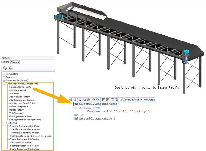
General
iLogic Enhancements

New iLogic Components and Management Behavior
Multiple new iLogic assembly functions make it easier for you to write rule code to add, modify,
and delete components and constraints. Here are some examples:

1. Components.Add: Ensures the component exists and that it has specified properties.
2. Components.AddiPart: Creates/updates an occurrence using an iPart factory and
   specification of a member.
3. ThisAssembly.BeginManage and ThisAssembly.EndManage: Allow you to delete
   components without specifically calling Components.Delete.

 In the following example, OptionA is a True/False parameter in the assembly. If the parameter
is set to True, the component named Occ A will be added or updated. If it is False, the
component won't be added or it will be deleted. iLogic ensures that Occ A is present if-and-
only-if OptionA is True.

When the EndManage code runs: If OptionA is false and if the component named Occ A already
exists in the assembly, it will be automatically deleted.

The principle is: Every time a BeginManage/EndManage block runs, you must call a function to
add only the components you want included in that block.

Important: iLogic uses the component name to determine which components to manage,
update, and delete. If you manually rename a managed occurrence, without updating the
managing iLogic rule, iLogic will stop managing it and create a new occurrence to replace the
renamed one.

For more information on the functions supported in iLogic, see iLogic API Reference.
New Document Units Geometry
 There are new functions which use document-units instead of database-units for the
coordinate values and objects representing Points, Vectors, and Matrices. These objects can be
used to specify the location and orientation of components created by Components.Add and
related functions. Use ThisDoc.Geometry.Point() or similar functions to create the objects.
property InDatabaseUnits can be used to retrieve the corresponding object in database units.
This is required when using Inventor API functions.

New iLogic Assembly Add Constraints Functions
The new iLogic Relationships (Add) functions allow you to create an iLogic assembly whose
occurrences and constraints are generated by a rule. The rule will re-generate or update the
content if any of the relevant parameters values are changed.

See below for the list of the new functions:

For more information, see iLogic API Reference
New Capture Current State Commands

 The Capture Current State command is enhanced to support the following:

 1. Capture Current State (Components.Add) Captures the state of the selected components
    using Components.Add. Ignores related constraints.
 2. Capture Current State (Components Constraints.Add) Captures the state of the selected
    components and related constraints using Components.Add.
 3. Capture Current State (Constraints.Add) Captures the state of the selected constraints
    using Constraints.Add. Only available if the file contains a constraint.
 4. Capture Current State (Patterns.Add) Captures the state of the selected pattern. Available
    if the file contains an assembly pattern.

The new Capture Current State              Here's an example of a rule generated from the
commands are available by right-clicking   Constraints.Add command. Once added to the rule editor,
on one or more files in the Rules Editor   you can make any modifications you want to the content
on the Model tab.                          directly in the rule editor.

  Multi-select components in the Model tree in the Rule Editor to capture the state of multiple
 components all at once. If you are capturing constraints between components, this ensures
 these are only captured once.
Use Assign Name to Identify Geometry for Constraints
You can now assign names to faces and edges, and then create a rule that adds the
constraint(s) directly to the face or edge with the assigned name.
Tip: Assign a descriptive name to the constrained geometry to make it easier to identify the
geometry in the rule editor.
To begin, assign a name to a face or edge:
Step 1 The assigned name displays in a new Geometry
In a part file, right-click on the geometry that is tab in the iLogic browser and on the geometry
or will be constrained to another part, and in the graphics window (part file only).
select Assign Name. Tip: Turn on and off the display of the assigned
name in the graphics window using the context
menu option Show/Hide Label.Next, create a rule that will add the constraint(s) directly to faces and edges with the assigned
names:
The rule editor populates with the new rule. The
Step 2the assembly file, in the Edit Rule dialog constraint will be re-created whenever you run the rule. If
box on the Model tab, multi-select the part the geometry was not assigned a name in the part file, the
names, right-click, and then select Rule Editor creates a generic name for the geometry.
Capture.Current.State (Components
Constraints.Add) from the context menu.
There is no associativity between the assigned name and the Rule Editor. If you change an
assigned name in a part file, you will need to recreate the rule or manually change the assigned
name in the rule editor.
Enhancement to the iLogic Help for Functions
Help for iLogic functions and arguments are now available from the iLogic API Referencehelp
node. This help content is in english only.Hole Feature Productivity, Workflow, and UI Enhancements
Productivity Enhancements
The new hole command provides the following productivity enhancements:
Faster Streamlined workflow reduces clicks, mouse movement, and
context switching thereby significantly increasing speed and
productivity. Additional performance improvements are made by
loading thread and clearance data.
Smarter We have simplified the placement selection types. You no longer
need to pick which one you want. It is inferred from your
interactions.
Robust You can add more than one hole without first creating a sketch.
Flexible Rapid linear offset dimensions to position a hole, as well as
concentric constraints, the command creates the underlying
sketch.
Seamless workflow Move between hole definition and sketch to add or modify
properties and switch back
What you need when you In-context dimensions replace the Mini Toolbar to allow for direct
need it access to parameters when interacting with your model.User Interface Enhancements The Hole command provides a streamlined workflow and hole presets for easy re-use.
Key Concepts
Streamlined Workflow
                       The property panel workflow is top to bottom.
                       That is, any property you set or change can affect
                       the properties in sections below it, but those
                       properties do not affect the properties in
                       preceding sections.

                       Improved dimension order allows faster value
                       entry for holes.

                       allow for creation and re-use of often used
                       property sets.

                       Breadcrumbs aid in feature creation and edit. In
Breadcrumb             the image (left), a hole feature (Hole3) is being
                       edited, you can click on 'Sketch4' to edit the
                       sketch or you can click on 'Hole3' to edit feature
                       defining parameters.

                       Panel sections can be expanded or collapsed to
Expand/Collapse        suit your use, personalizing the use interface for
                       often or seldom used parameters. Panel sections
                       remember the last used state between uses.

Panel menu             The drop down provides access to Help and
                       other advanced settings. The menu adjusts
                       based on context. For example, one list for the
                       property panel, one for the model browser, and
                       so on.
Color Scheme Enhancement New and Improved Color Scheme Editor Previously you needed to install the Color Scheme Editor from a separate installer, and the dialog box was not available from within Inventor. With Inventor 2019, the Color Scheme Editor is installed with Inventor and access to the Color Scheme Editor is available directly from the Application Options/Color tab. Click Customize Schemes to open the Color Scheme Editor and create your own custom color schemes. In addition, the Color Scheme Editor is enhanced as follows: 1. Edits are saved directly to the Application Options .xml file. Previously any modifications you made required you to save to the registry. 2. Provides settings to create new schemes and remove a scheme from the xml. 3. Custom color schemes are exported/imported to and from the Application Options .xml file using the Export and Import buttons on the Application Options dialog box. An Inventor® Ideas submission
Performance Improvements
 Significant performance improvements are seen in the following areas (Assembly related
improvements are not available in Inventor LT):
General Modeling

1. Threaded Hole - display has been optimized for better performance. Improvement is most
   noticeable in models with many threaded holes.
2. Zoom speed when using the mouse wheel has been significantly improved for large
   assemblies.

Assembly Modeling

1. In-place Edit - improved performance when entering and exiting in-place edit.
2. Design View - activation speed has been significantly improved.
3. Positional Representations - global update performance improvements for positional
    representations resulting in faster switching between Pos Reps, LODs, and so on. Additional
    efficiencies were achieved by updating only participating components.
4. Section View - improved performance when using the section view command in Full mode.
    Significant improvement in dragging the section plane during preview and with
    pan/zoom/rotate viewing tools.
5. Assembly Features - significant performance improvements affecting workflows using
    assembly updates, rebuild all, and updates during file open operations.
6. Express Mode - additional commands are now available in Express Mode. See .
7. Drive Constraint - improvement based on better management of assembly conditions not
    directly involved in driving constraints.
8. Replace All - for models where a component has a large number of instances (e.g. 300+)
    the performance is significantly improved.
9. Component Pattern Selection - significant performance improvements in selecting
    component patterns both for initial selection and subsequent selection.
10. Shrinkwrap - Detect Features exposes hidden component features, making it easy to
    exclude or include those features.
11. Frame Generator - general update performance improvements. The degree of
    improvement differs from one dataset to another.
12. Migration - applies to legacy assemblies, releases 2012 and prior. Performance of
    migration from Color Styles to Consistent Materials has been improved.
Drawing
Drawing view improvements are more noticeable for views of larger assemblies. Improvements
in the following areas are included:
1. View creation when using hidden line removed and shaded view for base and projected
views.
2. View navigation during view previews.
3. View updates for views using Design View, Level of Detail, and Positional representations
including those with visible surfaces.
4. Projected View - improved performance when using the Projected View command with a
placed view. Not applicable to projected view creation during base view placement.
5. Reference Part preview is improved for views where the reference parts extend beyond
the view margins.
Other General Enhancements
Language Pack Templates Now Install Under the Local Folder
When you install a language pack, the Inventor template files now install under the respective
local folder (\Templates\{locale} folder).
English language pack example:
Note: If you've installed a language pack, use the drawing template located in the templates
language folder, for example, Public\Documents\Autodesk\Inventor 2019\Templates\ja-
JP\Standard.dwg. You may encounter style conflicts using the drawing template located in the
standard directory, Public\Documents\Autodesk\Inventor 2019\Templates\Standard.dwg
template.Migrate Custom Settings Previously, you used xml files to migrate customization and Application Options settings to a new release. If an older supported version is detected when you install Inventor 2019, the Migrate Custom Settings dialog appears. Use this dialog to update Inventor with your customization and Application Option settings without the need to use the xml export/import process. If you close the dialog without migrating, you can migrate the settings later. Click Tools tabOptions panelMigrate Settings . 1. Supported older versions are Inventor 2018 or newer. 2. Restart Inventor after you migrate the settings.
A new option was added to Configure Options Settings that allows administrators to control
the use of Migrate Custom Settings in a deployment.

Clear the check box for Allow users to migrate custom settings from previous versions to block
the Migrate Custom Settings command. If the box is not checked, Migrate Custom Settings is
not installed with the deployment and is not available in the Tools tab. Check the box to install
Migrate Custom Settings.

Transparent Background Export Enhancement
When you export an Inventor file as a PNG, TIFF or BMP image with a transparent background,
the XYZ triad is no longer included in the exported image.
Guided Tutorials
New Tutorials
The Guided Tutorial learning content grew significantly this year. The gallery now contains 32
Autodesk authored tutorials, and 6 created by educational content developer Pluralsight LLC.
The Pluralsight tutorials are available in English only.

To access the guided tutorials, click the Get Started tab > Tutorial Gallery > Available Tutorials.

The following are new tutorials added for 2018 and 2019:

• ACAD Import
• AnyCAD for Fusion 360
• Apply Shape Generator
• Assembly 3D Annotation
• Basic Part Modeling: Shelf Support Bracket (Pluralsight)
• Basic Sweep: Cotter Pin (Pluralsight)
• Create a linear drive assembly
• Create and Analyze Tolerance Features (2019)
• Create and Use Sketch Blocks
• Create Detail Drawings
• Create GD&T Tolerance Features
• Create Plastic Part Features 1 of 2
• Create Plastic Part Features 2 of 2
• Design Accelerator - Shafts and Gears
• Fully-Constraining a Sketch (Pluralsight)
• Loft Basics: Creating a Vacuum Attachment (Pluralsight)
• Sheet Metal 3 v2
• Sheet Metal Design
• Shrinkwrap for General Use
• Understanding Extrude Extents (Pluralsight)
• Understanding Revolve Extents
New content is added frequently, so check the gallery often!
You can also read