USER MANUAL WAP-5903 WIFI 5 MESH-ENHANCED EXTENDER - VERSION A1.0, MAY 21, 2020 - COMTREND
←
→
Page content transcription
If your browser does not render page correctly, please read the page content below
USER MANUAL
  WAP-5903
  WiFi 5 Mesh-Enhanced Extender

                          Version A1.0, May 21, 2020

261072-045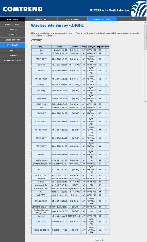
Preface
This manual provides information related to the installation and operation of this
device. The individual reading this manual is presumed to have a basic
understanding of telecommunications terminology and concepts.

If you find the product to be inoperable or malfunctioning, please contact technical
support for immediate service by email at INT-support@comtrend.com

For product update, new product release, manual revision, or software upgrades,
please visit our website at http://www.comtrend.com

EU Liaison Office :
COMTREND CORPORATION / Fijenhof 2, 5662AE Eindhoven, The Netherlands
Comtrend Central Europe, s.r.o. / nkovcova 1518/2, 170 00 Praha 7

Important Safety Instructions
With reference to unpacking, installation, use, and maintenance of your electronic
device, the following basic guidelines are recommended:

•   Do not use or install this product near water, to avoid fire or shock hazard. For
    example, near a bathtub, kitchen sink or laundry tub, or near a swimming pool.
    Also, do not expose the equipment to rain or damp areas (e.g. a wet
    basement).

•   To safeguard the equipment against overheating, make sure that all openings in
    the unit that offer exposure to air are not blocked.

•   Avoid using a telephone (other than a cordless type) during an electrical storm.
    There may be a remote risk of electric shock from lightening. Also, do not use
    the telephone to report a gas leak in the vicinity of the leak.

CAUTION:
     n       Changes or modifications to this unit not expressly approved by the party
             responsible for compliance could void the user authority to operate the
             equipment.
     n       Do not stack equipment or place equipment in tight spaces, in drawers, or
             on carpets. Be sure that your equipment is surrounded by at least 2
             inches of air space.
     n       If you experience trouble with this equipment, disconnect it from the
             network until the problem has been corrected or until you are sure that
             equipment is not malfunctioning.

     WARNING
         •     Disconnect the PLC from the power source before servicing
         •     For indoor user only
         •     Do NOT open the casing
         •     Do NOT use near water
         •     Do NOT insert sharp objects into the adapter’s socket
    nPower    Specifications:
             I/P: 100-240Vac, 50/60Hz, 0.6A

                                            1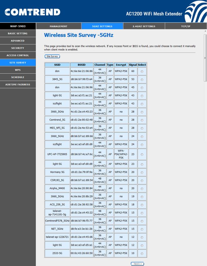
User Information
Any changes or modifications not expressly approved by the party responsible for
compliance could void your authority to operate the equipment.

Aucune modification apportée à l’appareil par l’utilisateur, quelle qu’en soit la
nature. Tout changement ou modification peuvent annuler le droit d’utilisation de
l’appareil par l’utilisateur.

Note: This equipment has been tested and found to comply with the limits for a
Class B digital device, pursuant to part 15 of the FCC Rules. These limits are
designed to provide reasonable protection against harmful interference in a
residential installation. This equipment generates, uses and can radiate radio
frequency energy and, if not installed and used in accordance with the instructions,
may cause harmful interference to radio communications. However, there is no
guarantee that interference will not occur in a particular installation. If this
equipment does cause harmful interference to radio or television reception, which
can be determined by turning the equipment off and on, the user is encouraged to
try to correct the interference by one or more of the following measures:

—Reorient or relocate the receiving antenna.
—Increase the separation between the equipment and receiver.
—Connect the equipment into an outlet on a circuit different from that to which the
receiver is connected.
—Consult the dealer or an experienced radio/TV technician for help.

This device complies with Part 15 of the FCC Rules. Operation is subject to the
following two conditions: (1) This device may not cause harmful interference, and
(2) this device must accept any interference received, including interference that
may cause undesired operation.

This Class B digital apparatus complies with Canadian ICES-003.
To reduce potential radio interference to other users, the antenna type and
its gain should be so chosen that the equivalent isotropically radiated power
(e.i.r.p.) is not more than that permitted for successful communication.
This device complies with Part 15 of the FCC Rules and Industry Canada licence-
exempt RSS standard(s).

Operation is subject to the following two conditions:
1. This device may not cause interference, and
2. This device must accept any interference, including interference that may
cause undesired operation of the device.

Cet appareil numérique de la classe B est conforme à la norme NMB-003 Canada.
Pour réduire le risque d’interférence aux autres utilisateurs, le type d’antenne
et son gain doivent être choisies de façon que la puissance isotrope
rayonnée équivalente (PIRE) ne dépasse pas ce qui est nécessaire pour une
communication réussie.
Cet appareil est conforme à la norme RSS Industrie Canada exempts de licence
norme(s).

Son fonctionnement est soumis aux deux conditions suivantes:
1. Cet appareil ne peut pas provoquer d’interférences et
2. Cet appareil doit accepter toute interférence, y compris les interférences
qui peuvent causer un mauvais fonctionnement du dispositif.

Radiation Exposure

FCC
1. This Transmitter must not be co-located or operating in conjunction with any
other antenna or transmitter.

                                          2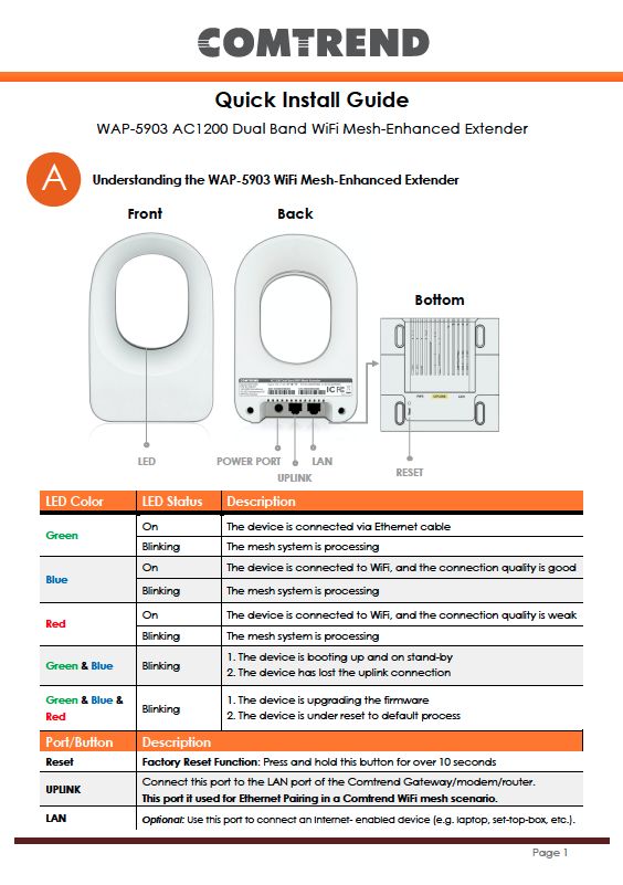
2. This equipment complies with FCC RF radiation exposure limits set forth for an
uncontrolled environment. This equipment should be installed and operated with a
minimum distance of 25 cm between the radiator and your body.

ISED
This device complies with the ISED radiation exposure limit set forth for an
uncontrolled environment. This device should be installed and operated with
minimum distance 25 cm between the radiator & your body. This transmitter must
not be co-located or operating in conjunction with any other antenna or
transmitter.

“This product meets the applicable Innovation, Science and Economic
development Canada technical specifications”.

The device for operation in the band 5150–5250 MHz is only for indoor use to
reduce the potential for harmful interference to co-channel mobile satellite
systems.

This product meets the applicable Industry Canada technical specifications.

The Ringer Equivalence Number (REN) indicates the maximum number of devices
allowed to be connected to a telephone interface. The termination of an interface
may consist of any combination of devices subject only to the requirement that the
sum of the RENs of all the devices not exceed five.

Cet équipement est conforme avec l'exposition aux radiations ISED définies pour
un environnement non contrôlé. Cet équipement doit être installé et utilisé à une
distance minimum de 25 cm entre le radiateur et votre corps. Cet émetteur ne doit
pas être co-localisées ou opérant en conjonction avec une autre antenne ou
transmetteur.

«Ce produit est conforme aux spécifications techniques applicables d'Innovation,
Sciences et Développement économique Canada».

les dispositifs fonctionnant dans la bande 5150-5250 MHz sont réservés
uniquement pour une utilisation à l’intérieur afin de réduire les risques de
brouillage préjudiciable aux systèmes de satellites mobiles utilisant les
mêmes canaux.

Le présent matériel est conforme aux specifications techniques applicables
d’Industrie Canada.

L’indice d’équivalence de la sonnerie (IES) sert à indiquer le nombre maximal de
terminaux qui peuvent être raccordés à une interface téléphonique. La terminaison
d’une interface peut consister en une combinaison quelconque de dispositifs, à la
seule condition que la somme d’indices d’équivalence de la sonnerie de tous les
dispositifs n’excède pas cinq.

Le numéro REN (Ringer Equivalence Number) indique le nombre maximal de
périphériques pouvant être connectés à une interface téléphonique. La terminaison
d'une interface peut consister en une combinaison quelconque d'appareils, à la
condition que la somme des REN de tous les appareils ne dépasse pas cinq.

Certification
    ● FCC / IC standard
              Part 15B / ICES-003
              Part 15C / RSS-247( 2.4GHz )
              Part 15E / RSS-247( 5GHz )

                                         3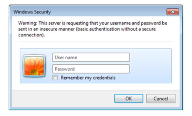
TIA-968 / IC-CS03
             UL 62368-1 / CSA 62368-1

Copyright
Copyright©2019 Comtrend Corporation. All rights reserved. The information
contained herein is proprietary to Comtrend Corporation. No part of this document
may be translated, transcribed, reproduced, in any form, or by any means without
prior written consent of Comtrend Corporation.

Protect Our Environment

         This symbol indicates that when the equipment has reached the end of
its
         useful life, it must be taken to a recycling centre and processed separate
         from domestic waste.

                                        4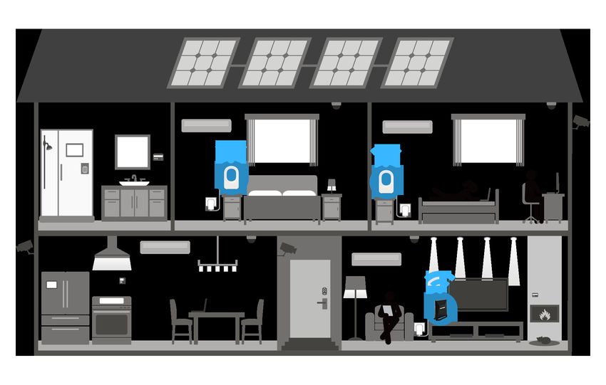
CATALOG
...................................................................................................................................................................... 0
CHAPTER 1 QUICK INSTALLATION .................................................................................................. 6
CHAPTER 2: WEB USER INTERFACE .............................................................................................. 14
 2.1 DEFAULT SETTINGS............................................................................................................................ 14
 2.2 IP CONFIGURATION ............................................................................................................................ 16
 2.3 LOGIN PROCEDURE ............................................................................................................................ 18
CHAPTER 3 MANAGEMENT............................................................................................................... 20
 3.1 STATUS............................................................................................................................................... 20
 3.2 STATISTICS ......................................................................................................................................... 21
 3.3 TIME ZONE SETTING .......................................................................................................................... 22
 3.4 TR-069 CONFIG ................................................................................................................................. 23
 1.5    WIFIXTEND CONFIG ................................................................................................................. 25
 3.6 UPGRADE FIRMWARE ......................................................................................................................... 26
 3.7 SAVE/RELOAD SETTING ..................................................................................................................... 27
 3.8 PASSWORD ......................................................................................................................................... 28
 3.9 LOGOUT ............................................................................................................................................. 29
CHAPTER 4 5GHZ SETTINGS ............................................................................................................. 30
 4.1 BASIC SETTING .................................................................................................................................. 30
 4.2 ADVANCED ........................................................................................................................................ 32
 4.3 SECURITY .......................................................................................................................................... 34
 4.4 ACCESS CONTROL ............................................................................................................................. 35
 4.5 SITE SURVEY ..................................................................................................................................... 36
 4.6 WPS .................................................................................................................................................. 37
 4.7 SCHEDULE ......................................................................................................................................... 38
 4.8 AIRTIME FAIRNESS ............................................................................................................................ 39
CHAPTER 5 2.4GHZ SETTINGS .......................................................................................................... 41
 5.1 BASIC SETTING .................................................................................................................................. 41
 5.2 ADVANCED ........................................................................................................................................ 43
 5.3 SECURITY .......................................................................................................................................... 45
 5.4 ACCESS CONTROL ............................................................................................................................. 46
 5.5 SITE SURVEY ..................................................................................................................................... 47
 5.6 WPS .................................................................................................................................................. 49
 5.7 SCHEDULE ......................................................................................................................................... 50
 5.8 AIRTIME FAIRNESS ............................................................................................................................ 51
CHAPTER 6 TCP/IP ................................................................................................................................ 53
 4.1 LAN SETTING .................................................................................................................................... 53
APPENDIX A: SPECIFICATIONS ........................................................................................................ 54

The setup images used in this manual are for reference only. The contents of these
images may vary according to firmware version. The official image contents are
based on the newest firmware version.

                                                                                  5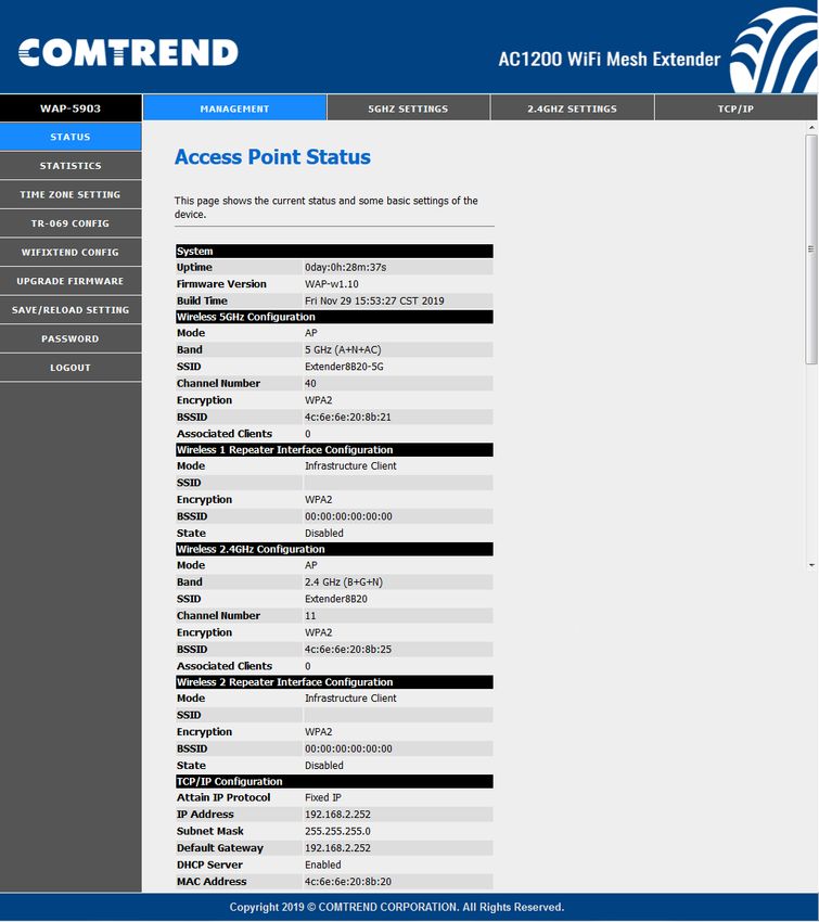
Chapter 1 Quick Installation
1. Package Contents
- WAP-5903 Wireless Mesh Extender
- Quick Installation Guide (QIG)
- Power Adapter
- Ethernet Cable
2. System Requirements
l Computer or network devices with wired or wireless network interface
card.
l Any connected devices must feature a network port.
l Web browser (Microsoft Internet Explorer 8.0 or above, Google Chrome
web browser, Opera web browser, or Safari web browser).
3. WAP-5903 Overview
The WAP-5903 Wireless Mesh Extender provides a simple way to “extend” your
wireless signal to areas with weak or nonexistent coverage, and to build-up a WiFi
mesh network in your home/office.
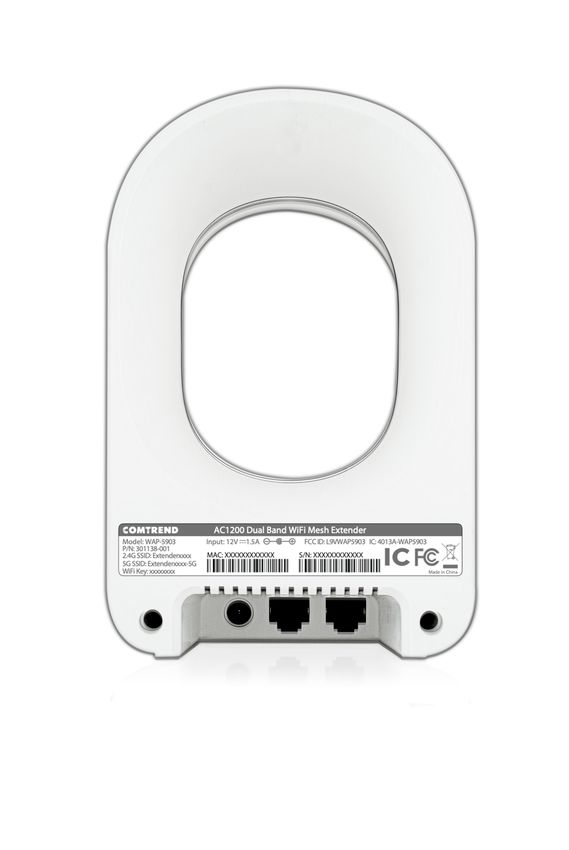
4. Hardware Explanation
Port / Button Description
Factory Reset Function: Press and hold this button for over 10
RESET Button
seconds
Connect this port to the LAN port of the home broadband
UPLINK Port router
Ethernet Pairing: Working in Comtrend WiFi mesh scenario
This port can also be used to connect to a pc/notebook for
LAN Port
Internet access
6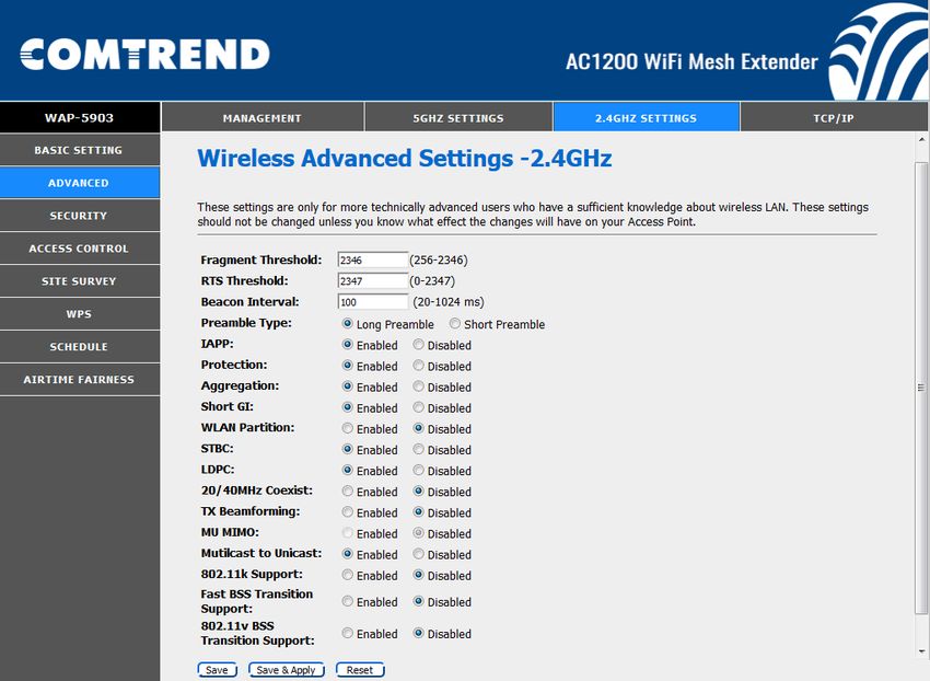
LED Explanation

      LED Color        LED Status                     Description

                          On        The device is connected via Ethernet cable
        Green

                        Blinking    The mesh system is processing

                                    The device is connected to WiFi, and the
                          On
                                    connection quality is GOOD
         Blue

                        Blinking    The device is booting up

                                    The device is connected to WiFi, and the
                          On
                                    connection quality is WEAK
         Red

                        Blinking    The mesh system is processing

    Green & Blue                    1. The device is standing by after booting up
                        Blinking
                                    2. The device lost the uplink connection

  Green & Blue & Red                1. The device is under firmware upgrade
                        Blinking
                                    2. The device is under reset to default process

                                        7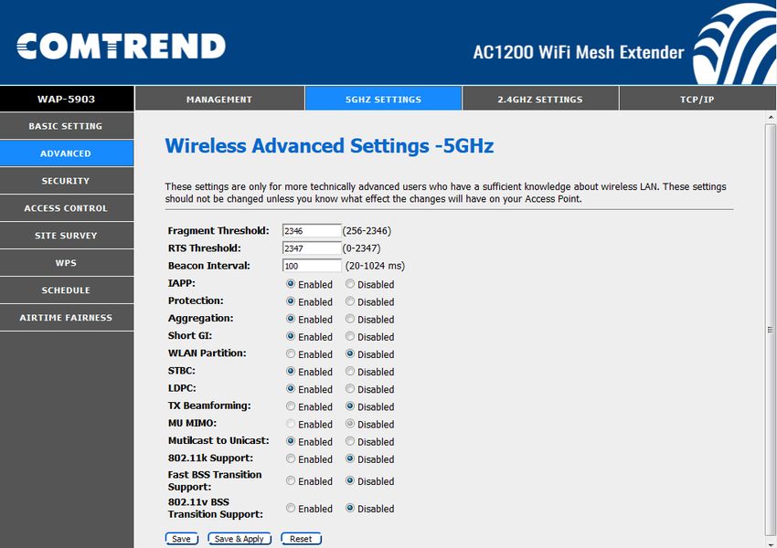
Quick Install Guide
          WAP-5903 AC1200 Dual Band WiFi Mesh-Enhanced Extender

A        Understanding the WAP-5903 WiFi Mesh-Enhanced Extender

                 Front                         Back

                                                                                Bottom

                 LED

                                                                           RESET

LED Color        LED Status        Description
                 On                The device is connected via Ethernet cable
Green
                 Blinking          The mesh system is processing
                 On                The device is connected to WiFi, and the connection quality is good
Blue
                 Blinking          The mesh system is processing

                 On                The device is connected to WiFi, and the connection quality is weak
Red
                 Blinking          The mesh system is processing

                                   1. The device is booting up and on stand-by
Green & Blue     Blinking
                                   2. The device has lost the uplink connection

Green & Blue &                     1. The device is upgrading the firmware
                 Blinking
Red                                2. The device is under reset to default process

Port/Button      Description
Reset            Factory Reset Function: Press and hold this button for over 10 seconds
                 Connect this port to the LAN port of the Comtrend Gateway/modem/router.
UPLINK
                 This port it used for Ethernet Pairing in a Comtrend WiFi mesh scenario.
LAN              Optional: Use this port to connect an Internet- enabled device (e.g. laptop, set-top-box, etc.).

                                                     8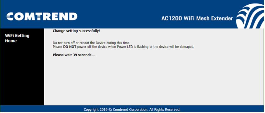
Choose One

                                   Scenario I:
          Setup with a Comtrend Gateway that supports WifiXtend2.0™
                             (Continue to Step B)

                                     Scenario II:
                 Setup with either a non-Comtrend Gateway or
            a Comtrend Gateway that does not support WifiXtend2.0™
                               (Continue to Step E)

    WifiXtend2.0™ is Comtrend’s WiFi Mesh technology for enhanced whole-home WiFi
    coverage. The WAP-5903 and select Comtend Gatways support WifiXtend2.0™. When
    WifiXtend2.0™ technologies are being utilized, the WiFi network will automatically
    become a single network with one SSID and Password per band.

B   Scenario I: Setting up the WiFi Mesh Extender with a Comtrend Gateway
    that Supports WifiXtend2.0™

    1. Use the included Ethernet cable to connect one end into the LAN port of the
       Comtrend Gateway that supports WifiXtend2.0™ and the other
       end into the UPLINK port of                                         WAP-5903
       the WAP-5903.

    2. Power on the WAP-5903 by
       connecting one end of the
       Power Adapter into the Power
       Port of the WAP-5903 and the
       other end into an outlet. The
       Ethernet Pairing will                      Power Plug
       automatically start processing
       and the WAP-5903’s LED will
       begin blinking green.
                                                                  Ethernet Cable
    3. Wait until the WAP-5903’s LED
       is solid green. This means that
       the WAP-5903 is paired and                      Comtrend Gateway
       grouped in the same WiFi
       mesh network as the
       Comtrend gateway.

    4. If you are setting up more
       than one WAP-5903, then please follow instructions 1-3 with the additional WAP-
       5903 units.

                                              9
C Deploy the WiFi Mesh Extender
5. After the WAP-5903 is paired, move it to the nearest outlet where additional WiFi
coverage is needed. Once it is plugged in, wait for the LED to light up solid blue,
which means it is ready.
LED Description
Solid The WAP-5903 is placed in an ideal location
Blue and is receiving a good WiFi signal.
The WAP-5903 is placed too far away from
the Comtrend Gateway, and is receiving a
Solid
weak WiFi signal. Action Required: Move
Red
the WAP-5903 closer to the Comtrend
Gateway.
D The WiFi Mesh Network is Ready to Use!
6. The WiFi mesh network is automatically using the original WiFi configuration on the
Comtrend Gateway. If you would like to further change the network settings, then
please refer to the Comtrend Gateway’s User Manual to make changes directly to
the Gateway.
E Scenario II: Setting up the WiFi Mesh Extender with a Non-Comtrend
Gateway/Comtrend Gateway that does not Support WifiXtend2.0™.
Note: This scenario requires at least two WAP-5903 units to create a connection.
101. Optional: Disable the WiFi on the non-Comtrend modem/router. This will help
improve the performance of the WiFi Mesh Extender and avoid confusing the
Internet-enabled devices.
WAP-5903
2. Use the included Ethernet
cable to connect one end
into the LAN port of the
existing home modem/router
and the other end into the
UPLINK port of the first WAP-
5903.
Power Plug
3. Power on this WAP-5903 by
connecting one end of the
Power Adapter into the Power
Port of the WAP-5903 and the Ethernet Cable
other end into an outlet.
Existing Modem/Router
F Setup the WiFi Network
4. You can now use your computer’s wireless configuration utility to
search for a Wireless Network name such as: Extender2368 or
Extender2368-5G. (The default SSID of this extender device is
‘Extender2368’, and 2368 is for reference. It is the last 4 digits of
the device’s MAC number.)
5. When you are prompted to input the security key, the WiFi Key
(password) can be found on the label at the back of the WAP-
5903 device.
116. Click the OK button to connect to the network.
7. Open your web browser, and input ‘http://extender-setup/’ in the address bar.
8. The system will prompt you to input the username and password. Default username
is ‘root’ and password is ‘12345’. Click the OK button to continue.
9. After logging into the Web page, input the new SSID for both the 2.4GHz and 5GHz
fields. The user can setup a new password by inputting it in both the Key fields. Click
the Apply/Save button to complete setup.
1210. After applying the wireless setting the WAP-5903 will reboot. When the WAP-5903’s
LED is solid green it means it is ready.
11. You can now connect the additional WAP-5903. Power on the additional WAP-
5903 by connecting one end of the Power Adapter into the Power Port of the
WAP-5903 and the other end into an outlet. The Ethernet Pairing will automatically
start processing and the WAP-5903’s LED will begin blinking green.
12. Wait until the WAP-5903’s LED is solid green. This means that the WAP-5903 is
paired and grouped in the same WiFi mesh network as the first WAP-5903.
13. You can now move the additional WAP-5903 extender to the nearest outlet where
more WiFi coverage is needed. Once plugged in, wait for the LED to light up solid
blue, which means it is ready.
13LED Description
The WAP-5903 is placed in an ideal
Solid
location and is receiving a good WiFi
Blue
signal.
The WAP-5903 is placed too far away from
the first WAP-5903 (i.e. the one connected
Solid
to the modem/router), and is receiving a
Red
weak WiFi signal. Action Required: Move
the WAP-5903 closer to the first WAP-5903.
14. Repeat steps 11-13 to add more WAP-5903 extenders to the mesh
network.
G The WiFi Mesh Network is Ready to Use!
FOR MORE HELP: For instructions on advanced features, FAQ, etc., please visit our
online Product Webpage.
For more information:
YouTube: https://www.youtube.com/user/ComtrendConnection
Facebook: https://facebook.com/Comtrend
Website: http://us.comtrend.com/
Support: Visit our website or call (949) 753-9640
Chapter 2: Web User Interface
2.1 Default Settings
The factory default settings of this device are summarized below.
• LAN IP address: 192.168.2.252
• LAN subnet mask: 255.255.255.0
• Administrative access (username: root , password: 12345)
• WLAN access: enabled
Technical Note
During power on, the device initializes all settings to default values. It will then read
the configuration profile from the permanent storage section of flash memory. The
default attributes are overwritten when identical attributes with different values are
configured. The configuration profile in permanent storage can be created via the
web user interface or telnet user interface, or other management protocols. The
factory default configuration can be restored either by pushing the reset button for
more than five seconds until the power indicates LED blinking or by clicking the
Restore Default Configuration option in the Restore Settings screen.
1415
2.2 IP Configuration
DHCP MODE

When the WAP-5903 powers up, the onboard DHCP server will switch on. Basically,
the DHCP server issues and reserves IP addresses for LAN devices, such as your
PC.

To obtain an IP address from the DCHP server, follow the steps provided below.

NOTE:    The following procedure assumes you are running Windows. However,
         the general steps involved are similar for most operating systems (OS).
         Check your OS support documentation for further details.
STEP 1: From the Network Connections window, open Local Area Connection (You
        may also access this screen by double-clicking the Local Area Connection
        icon on your taskbar). Click the Properties button.
STEP 2: Select Internet Protocol (TCP/IP) and click the Properties button.
STEP 3: Select Obtain an IP address automatically as shown below.

STEP 4: Click OK to submit these settings.

If you experience difficulty with DHCP mode, you can try static IP mode instead.

                                        16
STATIC IP MODE
In static IP mode, you assign IP settings to your PC manually.
Follow these steps to configure your PC IP address to use subnet 192.168.2.x.
NOTE: The following procedure assumes you are running Windows. However,
the general steps involved are similar for most operating systems (OS).
Check your OS support documentation for further details.
STEP 1: From the Network Connections window, open Local Area Connection (You
may also access this screen by double-clicking the Local Area Connection
icon on your taskbar). Click the Properties button.
STEP 2: Select Internet Protocol (TCP/IP) and click the Properties button.
STEP 3: Change the IP address to the 192.168.2.x (12.3 Login Procedure
Perform the following steps to login to the web user interface.
NOTE: The default settings can be found in 2.1 Default Settings.
STEP 1: Start the Internet browser and enter the default IP address for the device
in the Web address field. For example, if the default IP address is
192.168.2.252, type http://192.168.2.252.
STEP 2: A dialog box will appear, such as the one below. Enter the default
username and password, as defined in section 2.1 Default Settings.
Click OK to continue.
NOTE: If you can’t see the web management interface, and you’re being
prompted to input user name and password again, it means you didn’t input
username and password correctly. Please retype user name and password
again. If you’re certain about the user name and password you type are correct,
please go to section 3.7 to perform a factory reset or to set the password back
to the default value.
The login password can be changed later (see section3.8).
18STEP 3: After successfully logging in for the first time, you will reach this screen.
19Chapter 3 Management
3.1 Status
This page shows the current status and some basic settings of the device.
203.2 Statistics
This page shows the packet counters for transmission and reception regarding to
wireless and Ethernet networks.
213.3 Time Zone Setting
You can maintain the system time by synchronizing with a public time server over
the Internet.
Consult the table below for descriptions.
Heading Description
Current Time Input the current time manually or click on the Copy
Computer Time button
Time Zone Select Select your time zone from the Drop-down menu
Automatically Adjust Check the checkbox þ to select
Daylight Saving
Enable NTP client Check the checkbox þ to select
update
NTP server Select from the drop-down list or manually input the
NTP server address
223.4 TR-069 Config
This page is used to configure the TR-069 CPE. Here you may change the setting
for the ACS's parameters.
Consult the table below for descriptions.
Option Description
Enable TR-069 Select the Disabled or Enabled radio button to disable or
enable TR-069
ACS URL URL for the CPE to connect to the ACS using the CPE
WAN Management Protocol. This parameter MUST be in
the form of a valid HTTP or HTTPS URL. An HTTPS URL
indicates that the ACS supports SSL. The “host” portion
of this URL is used by the CPE for validating the
certificate from the ACS when using certificate-based
authentication.
ACS User Name Username used to authenticate the CPE when making a
connection to the ACS using the CPE WAN Management
Protocol. This username is used only for HTTP-based
authentication of the CPE.
23Option Description
ACS Password Password used to authenticate the CPE when making a
connection to the ACS using the CPE WAN Management
Protocol. This password is used only for HTTP-based
authentication of the CPE.
Periodic Inform Select the Disabled or Enabled radio button to disable or
Enable enable Periodic Inform. Whether enabled or not the CPE
MUST periodically send CPE information to the ACS using
the Inform method call.
Periodic Inform The duration in seconds of the interval for which the CPE
Interval attempts to connect with the ACE if periodic inform is
enabled
Connection Request
User Name Username used to authenticate an ACS making a
Connection Request to the CPE
Password Password used to authenticate an ACS making a
Connection Request to the CPE
Path The Path of the TR069 connection request URL
Port The Port of the TR-069 connection request URL
STUN Connection
STUN Select the Disabled or Enabled radio button to disable or
enable STUN
Server URL The URL for STUN server
Server Port The Port for STUN server
Username The Username for STUN server
Password The Password for STUN server
MaxKeepAlivePeriod The maximum value in seconds to check the server
connection
MinKeepAlivePeriod The minimum value in seconds to check the server
connection
241.5 WiFiXTEND Config
WifiXtend is a Whole-Home WiFi Mesh system that creaters an ultimate
WiFi Mesh network quickly and easily . Service providers can use WifiXtend to
deploy theirdevices into the WiFi Mesh system.
Select the required radio button to enable or disable. Then, click the Save & Apply
button to save and apply your changes.
253.6 Upgrade Firmware
This page allows you upgrade the Access Point firmware to new version. Please
note, do not power off the device during the upload because it may crash the
system.
STEP 1: Click the Browse button to select the required file.
STEP 2: Then, click the Upload button to upgrade the new firmware.
NOTE1: The update process will take a few minutes to complete. The device will
reboot and the browser window will refresh to the default screen upon successful
installation. It is recommended that you compare the Software Version on the
Status screen with the firmware version installed, to confirm the installation was
successful.
NOTE2: The Power LED indicates the status of firmware update progress. Please
DO NOT power off the device when Power LED is flashing or the device will be
damaged.
263.7 Save/Reload Setting
This page allows you save current settings to a file or reload the settings from the
file which was saved previously. Besides, you could reset the current configuration
to factory default.
Save Settings to File: Click the Save button to save your settings to a file on your
computer.
Load Settings from File: Click the Browse button to select the required file.
Then, click the Upload button to upgrade the new firmware.
Reset Settings to Default: Click the Reset button to display the following.
Click the OK button to proceed. Then you will need to wait for one minute for the
device to reboot.
273.8 Password
This page is used to set the account to access the web server of Access Point.
Empty user name and password will disable the protection.
STEP 1: Input the User Name.
STEP 2: Input the New Password.
STEP 3: Confirm the New Password by inputting it again.
STEP 4: Click the Save and Apply button to save and apply your change.
If you just click the Save button, it is saved to flash memory.
283.9 Logout
This page is used to logout.
29Chapter 4 5GHz Settings
4.1 Basic Setting
The Basic option allows you to configure basic features of the wireless LAN
interface. Among other things, you can enable or disable the wireless LAN
interface, hide the network from active scans, and set the wireless network name
(also known as SSID).
Heading Description
Disable Wireless LAN A checkbox þ that enables or disables the wireless
Interface LAN interface
Band Select from the drop-down menu
SSID Sets the wireless network name. SSID stands for
Service Set Identifier. All stations must be configured
[1-32 characters] with the correct SSID to access the WLAN. If the SSID
does not match, that user will not be granted access.
Channel Width Drop-down menu that allows the widening of the
signal for transferring data.
Control Sideband Select Upper or Lower sideband when in
20MHz/40MHz mixed mode.
DFS Channel If DFS channel is enabled, the access point can use
DFS channels reserved for radars.
Channel Number Drop-down menu that allows selection of a specific
channel.
Broadcast SSID If SSID broadcast is on, the access point will
broadcast the network name (SSID) every few
seconds, computers in the neighborhood are quickly
informed of the network
30Heading Description
WMM (Wi-Fi The technology maintains the priority of audio, video
Multimedia) and voice applications in a Wi-Fi network. It allows
multimedia service get higher priority.
Data Rate Drop-down menu that allows the changing of the data
rate for transferring data.
TX restrict Transmission limit
RX restrict Receive limit
Associated Clients Display connected device information including (MAC
Address, Mode, Tx Packet…)
314.2 Advanced
These settings are only for more technically advanced users who have a sufficient
knowledge about wireless LAN. These settings should not be changed unless you
know what effect the changes will have on your Access Point.
Heading Description
Fragment Threshold Set the Fragment threshold of wireless radio.
Do not modify the default value if you don’t
know what it is, default value is 2346.
RTS Threshold The RTS (Request To Send) threshold parameter
controls what size data packet (number of bytes) the
low level RF protocol issues to an RTS packet. Do not
modify the default value if you don’t know what
it is, default value is 2347.
Beacon Interval The Beacon Interval value indicates the frequency
interval of the beacon. A beacon is a packet broadcast
by the Router to synchronize the wireless network. Do
not modify the default value if you don’t know
what it is, default value is 100.
IAPP Click to enable or disable the IEEE 802.11f Inter-
Access Point Protocol (IAPP)
Protection Click to enable or disable the Management Frame
Protection
Aggregation Frame aggregation is a feature of the IEEE 802.11e,
802.11n and 802.11ac wireless LAN standards that
increases throughput by sending two or more data
frames in a single transmission.
Click to enable or disable.
32Heading Description
Short GI Short GI(Short Guard Interval) guard intervals are
used to ensure that distinct transmissions do not
interfere with one another, or otherwise cause
overlapping transmissions. Click to enable or disable.
WLAN Partition WLAN Partition prevents associated wireless clients
from communicating with each other. Click to enable
or disable.
STBC By enabling Space-Time Block Coding (STBC), the
transmission rate is reduced; however the
transmission quality is improved. Click to enable or
disable.
LDPC Low-Density Parity Check (LDPC)
In the 802.11 association process, the LDPC-encoded
frame is negotiated. If the peer indicates that the
LDPC is supported in the Beacon or Association
Request frame, the 802.11n device only transmits the
LDPC-encoded frame.
Click to enable or disable.
TX Beamforming Beamforming Beam, which can be directional to
transmit signals, mainly for the receiver.
Click to enable or disable.
MU MIMO MU-MIMO (Multi-User MIMO), at the same time, data
can be transferred to multiple users at the same time.
Click to enable or disable.
Multicast to Unicast Multicast: this article is about one-to-many
communications
Unicast: refers to a one-to-one transmission from one
point in the network to another point.
Click to enable or disable.
802.11k Support Helps the client to generate the optimized AP list for
Wi-Fi roaming.
Click to enable or disable.
Fast BSS Transition Provides a quick authentication method for Wi-Fi
Support roaming.
Click to enable or disable.
802.11v BSS Transition Provides wireless network management to assist client
Support roaming to better AP.
Click to enable or disable.
334.3 Security
This page allows you setup the wireless security. Turn on WEP or WPA by using
Encryption Keys could prevent any unauthorized access to your wireless network.
Heading Description
Select SSID Select the wireless network name from the drop-down
box. SSID stands for Service Set Identifier. All
stations must be configured with the correct SSID to
access the WLAN. If the SSID does not match, that
client will not be granted access.
Encryption This option specifies whether a network key is used
for authentication to the wireless network. If network
authentication is set to Disable, then no authentication
is provided. Despite this, the identity of the client is
still verified. Each authentication type has its own
settings.
Authentication Mode Select the authentication server(RADIUS)
authentication or personal authentication
WPA2 Cipher Suite Select WPA2 type of encryption
Management Frame Provide protection for unicast and multicast
Protection management action frames
Pre-Shared Key Format Pre-Shared Key Format has Passphrase and HEX(64
characters)
Pre-Shared Key Pre-shared key (PSK) is a shared secret which was
previously shared between the two parties using some
secure channel before it needs to be used
344.4 Access Control
If you choose 'Allowed Listed', only those clients whose wireless MAC addresses are
in the access control list will be able to connect to your Access Point. When 'Deny
Listed' is selected, these wireless clients on the list will not be able to connect the
Access Point.
Note:
Mac Address format: 831bf4d5c14
No colons between characters required
354.5 Site Survey
This page provides tool to scan the wireless network. If any Access Point or IBSS is
found, you could choose to connect it manually when client mode is enabled.
364.6 WPS
This page allows you to change the setting for WPS (Wi-Fi Protected Setup). Using
this feature could let your wireless client automatically synchronize its setting and
connect to the Access Point in a minute without any hassle.
Consult the table below for descriptions.
Heading Description
Disable WPS A checkbox þ that enables or disables the Wi-Fi
Protected Setup (WPS)
Self-PIN Number This AP itself is the WPS Personal Identification
Number
Push Button Start Wi-Fi Simple Configuration process
Configuration
Stop WSC Stop Wi-Fi Simple Configuration process
Client-PIN Number Shows the current value of client PIN
Current Key Info Shows Wi-Fi Security information
374.7 Schedule
This page allows you setup the wireless schedule rule. Please do not forget to
configure system time before enable this feature.
Consult the table below for descriptions.
Heading Description
Enable Wireless A checkbox þ that enables or disables the wireless schedule
Schedule
Enable A checkbox þ that enables or disables an entry
Day Select the day form the drop-down menu
From Select the hour and the minute form the drop-down menu
To Select the hour and the minute form the drop-down menu
384.8 Airtime Fairness
Airtime Management, sometimes called Airtime Fairness is based on TDMA (Time
Division Multiple Access) technology. This function can allocate airtime time evenly
or set a dedicated airtime to a different network (by SSID) or devices (by Mac/IP
address). The Allocation is used to make all clients getting airtime fairly or make
some network or device getting airtime proportional. In this way, the capacity and
efficiency of Wi-Fi will be improved.
Select SSID Mode from the drop-down menu to display the following.
To apply your changes, click the Apply Changes button.
Heading Description
Equal Airtime Set equal airtime for all Wi-Fi netoworks.
Across all Click to enable or disable.
Networks
Root AP Allocation (percentage) for Root AP
RepeaterClient Allocation (percentage) for Repeater Client
39Select Device Mode from the drop-down menu to display the following.
To apply your changes, click the Apply Changes button.
Heading Description
Equal Airtime Set equal airtime for all devices.
Across all Click to enable or disable.
Devices
IP / MAC Device information for Airtime Priorities
Allocation Allocation (percentage) for this device
Comment A note for this client
Click the Add Station button to add the station.
40Chapter 5 2.4GHz Settings
5.1 Basic Setting
The Basic option allows you to configure basic features of the wireless LAN
interface. Among other things, you can enable or disable the wireless LAN
interface, hide the network from active scans, and set the wireless network name
(also known as SSID).
Heading Description
Disable Wireless LAN A checkbox þ that enables or disables the wireless
Interface LAN interface
Band Select from the drop-down menu
SSID Sets the wireless network name. SSID stands for
Service Set Identifier. All stations must be configured
[1-32 characters] with the correct SSID to access the WLAN. If the SSID
does not match, that user will not be granted access.
Channel Width Drop-down menu that allows the widening of the
signal for transferring data.
Control Sideband Select Upper or Lower sideband when in
20MHz/40MHz mixed mode.
Channel Number Drop-down menu that allows selection of a specific
channel.
Broadcast SSID If SSID broadcast is on, the access point will
broadcast the network name (SSID) every few
seconds, computers in the neighborhood are quickly
informed of the network
WMM (Wi-Fi The technology maintains the priority of audio, video
Multimedia) and voice applications in a Wi-Fi network. It allows
multimedia service get higher priority.
41Heading Description
Data Rate Drop-down menu that allows the changing of the data
rate for transferring data.
TX restrict Transmission limit
RX restrict Receive limit
Associated Clients Display connected device information including (MAC
Address, Mode, Tx Packet…)
425.2 Advanced
These settings are only for more technically advanced users who have a sufficient
knowledge about wireless LAN. These settings should not be changed unless you
know what effect the changes will have on your Access Point.
Heading Description
Fragment Threshold Set the Fragment threshold of wireless radio.
Do not modify the default value if you don’t
know what it is, default value is 2346.
RTS Threshold The RTS (Request To Send) threshold parameter
controls what size data packet (number of bytes) the
low level RF protocol issues to an RTS packet. Do not
modify the default value if you don’t know what
it is, default value is 2347.
Beacon Interval The Beacon Interval value indicates the frequency
interval of the beacon. A beacon is a packet broadcast
by the Router to synchronize the wireless network. Do
not modify the default value if you don’t know
what it is, default value is 100.
Preamble Type Preamble Type setting indicates the length of the CRC
(Cyclic Redundancy Check) block:
Long preamble: Provides better compatibility for older
client or high interference environment.
Short preamble: Provides better performance for
newer clients.
Check to choose "Long preamble" or "Short preamble"
IAPP Click to enable or disable the IEEE 802.11f Inter-
Access Point Protocol (IAPP)
43Heading Description
Protection Click to enable or disable the Management Frame
Protection
Aggregation Frame aggregation is a feature of the IEEE 802.11e,
802.11n and 802.11ac wireless LAN standards that
increases throughput by sending two or more data
frames in a single transmission.
Click to enable or disable.
Short GI Short GI(Short Guard Interval) guard intervals are
used to ensure that distinct transmissions do not
interfere with one another, or otherwise cause
overlapping transmissions. Click to enable or disable.
WLAN Partition WLAN Partition prevents associated wireless clients
from communicating with each other. Click to enable
or disable.
STBC By enabling Space-Time Block Coding (STBC), the
transmission rate is reduced; however the
transmission quality is improved. Click to enable or
disable.
LDPC Low-Density Parity Check (LDPC)
In the 802.11 association process, the LDPC-encoded
frame is negotiated. If the peer indicates that the
LDPC is supported in the Beacon or Association
Request frame, the 802.11n device only transmits the
LDPC-encoded frame.
Click to enable or disable.
20/40MHz Coexist If enabled, when interference occurs, it will be
(WLAN2 2.4GHz only) reduced to 20Mhz, and the speed will be reduced by
half to enhance anti-interference and friendliness.
TX Beamforming Beamforming Beam, which can be directional to
transmit signals, mainly for the receiver.
Click to enable or disable.
MU MIMO MU-MIMO (Multi-User MIMO), at the same time, data
can be transferred to multiple users at the same time.
Click to enable or disable.
Multicast to Unicast Multicast: this article is about one-to-many
communications
Unicast: refers to a one-to-one transmission from one
point in the network to another point.
Click to enable or disable.
802.11k Support Helps the client to generate the optimized AP list for
Wi-Fi roaming.
Click to enable or disable.
Fast BSS Transition Provides a quick authentication method for Wi-Fi
Support roaming.
Click to enable or disable.
802.11v BSS Transition Provides wireless network management to assist client
Support roaming to better AP.
Click to enable or disable.
445.3 Security
This page allows you setup the wireless security. Turn on WEP or WPA by using
Encryption Keys could prevent any unauthorized access to your wireless network.
Heading Description
Select SSID Select the wireless network name from the drop-down
box. SSID stands for Service Set Identifier. All
stations must be configured with the correct SSID to
access the WLAN. If the SSID does not match, that
client will not be granted access.
Encryption This option specifies whether a network key is used
for authentication to the wireless network. If network
authentication is set to Disable, then no authentication
is provided. Despite this, the identity of the client is
still verified. Each authentication type has its own
settings.
Authentication Mode Select the authentication server(RADIUS)
authentication or personal authentication
WPA2 Cipher Suite Select WPA2 type of encryption
Management Frame Provide protection for unicast and multicast
Protection management action frames
Pre-Shared Key Format Pre-Shared Key Format has Passphrase and HEX(64
characters)
Pre-Shared Key Pre-shared key (PSK) is a shared secret which was
previously shared between the two parties using some
secure channel before it needs to be used
455.4 Access Control
If you choose 'Allowed Listed', only those clients whose wireless MAC addresses are
in the access control list will be able to connect to your Access Point. When 'Deny
Listed' is selected, these wireless clients on the list will not be able to connect the
Access Point.
Note:
Mac Address format: 831bf4d5c14
No colons between characters required
465.5 Site Survey
This page provides tool to scan the wireless network. If any Access Point or IBSS is
found, you could choose to connect it manually when client mode is enabled.
4748
5.6 WPS
This page allows you to change the setting for WPS (Wi-Fi Protected Setup). Using
this feature could let your wireless client automatically synchronize its setting and
connect to the Access Point in a minute without any hassle.

Consult the table below for descriptions.

  Heading                   Description
  Disable WPS               A checkbox þ that enables or disables the Wi-Fi
                            Protected Setup (WPS)
  Self-PIN Number           This AP itself is the WPS Personal Identification
                            Number
  Push Button               Start Wi-Fi Simple Configuration process
  Configuration

  Stop WSC                  Stop Wi-Fi Simple Configuration process
  Client-PIN Number         Shows the current value of client PIN
  Current Key Info          Shows Wi-Fi Security information

                                            49
5.7 Schedule
This page allows you setup the wireless schedule rule. Please do not forget to
configure system time before enable this feature.
Consult the table below for descriptions.
Heading Description
Enable Wireless A checkbox þ that enables or disables the wireless schedule
Schedule
Enable A checkbox þ that enables or disables an entry
Day Select the day form the drop-down menu
From Select the hour and the minute form the drop-down menu
To Select the hour and the minute form the drop-down menu
505.8 Airtime Fairness
Airtime Management, sometimes called Airtime Fairness is based on TDMA (Time
Division Multiple Access) technology. This function can allocate airtime time evenly
or set a dedicated airtime to a different network (by SSID) or devices (by Mac/IP
address). The Allocation is used to make all clients getting airtime fairly or make
some network or device getting airtime proportional. In this way, the capacity and
efficiency of Wi-Fi will be improved.
Select SSID Mode from the drop-down menu to display the following.
To apply your changes, click the Apply Changes button.
Heading Description
Equal Airtime Set equal airtime for all networks.
Across all Click to enable or disable.
Networks
Root AP Allocation (percentage) for Root AP
RepeaterClient Allocation (percentage) for Repeater Client
51Select Device Mode from the drop-down menu to display the following.
To apply your changes, click the Apply Changes button.
Heading Description
Equal Airtime Set equal airtime for all devices.
Across all Click to enable or disable.
Devices
IP / MAC Device information for Airtime Priorities
Allocation Allocation (percentage) for this device
Comment A note for this client
Click the Add Station button to add the station.
52Chapter 6 TCP/IP
4.1 LAN Setting
This page is used to configure the parameters for local area network which
connects to the LAN port of your Access Point. Here you may change the setting for
IP address, subnet mask, DHCP, etc...
Consult the table below for descriptions.
Heading Description
IP Address Input the IP address for the LAN port
Subnet Mask Input the subnet mask for the LAN port
Default Gateway IP Address of the default gateway
DHCP Select the method to get an IP address, DHCP or
Static
Domain Name Display Host name
53Appendix A: Specifications
Hardware
.RJ-45 X 1 for LAN (10/100/1000)
.RJ-45 X 1 for UPLINK (10/100/1000)
.Reset button X 1
.Internal Antenna X 2
Ethernet
. IEEE 802.3, IEEE 802.3u
Management
. TR-069, SNMP, Telnet, Web- Based Management, Configuration Backup and
Restoration
. Software Upgrade via HTTP
Wireless
.IEEE 802.11n, 2.4GHz, 2T2R
Backward compatible with 802.11g/b
2412 – 2462 MHz ( for FCC / IC )
2412 – 2472 MHz ( for CE )
.IEEE 802.11ac,5GHz, 2T2R,
Backward compatible with 802.11n/a
U-NII-1 ( 5150~5250 MHz )
U-NII-2a ( 5250~5350 MHz ) optional
U-NII-2c/2e ( 5470~5725 MHz ) optional
U-NII-3 ( 5725~5825 MHz ) for FCC / IC only
WPA2/WPA2-PSK with TKIP & AES Security Type
.MAC Address Filtering
Power Supply
.External power adapter :
I/P: 100-240Vac, 50/60Hz, 0.6A
Environment
.Operating Temperature: 0°C ~40°C (32°F ~104°F)
.Operating Humidity: 10%~90% non-condensing
.Storage Temperature: -25°C ~65°C (-23°F ~149°F)
.Storage Humidity: 5%~90% non-condensing
Kit Weight
(1* WAP-5903, 1*RJ45 cable, 1*power adapter) = 0.75 kg
NOTE: Specifications are subject to change without notice.
54You can also read