Free Match Multi Zone Outdoor Units - User Manual Model No.: EAC2H18R2C EAC4H36R2C EAC3H24R2C EAC5H42R2C - EQK HVAC
←
→
Page content transcription
If your browser does not render page correctly, please read the page content below
Free Match Multi Zone Outdoor Units

User Manual
Model No.: EAC2H18R2C
           EAC4H36R2C
           EAC3H24R2C
           EAC5H42R2C

Thank you very much for purchasing our air conditioner. Please read this owen's manual carefully before
using your air conditioner.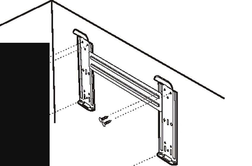
Safety Instructions                                                                       1
  Preparation before Use                                                                    3

  Safety Precautions                                                                        4

  Installation Instructions                                                                 5

  Care and Maintenance                                                                     17

  Protection                                                                               18

  Energy Saving Tips                                                                       19

  Troubleshooting                                                                          20

  Identification of Parts                                                                  21

  Display Introduction                                                                     22

THANK YOU
Congratulations on your purchase and welcome to the              Family.
Your new           Air Conditioner combines high-efficiency operation with portable convenience.
By following the operating and care instructions in this manual, your air conditioner will
provide you with many years of reliable service.
Please visit our website www.eqkhvac.com
For any questions or Technical Support,
please contact us by mail info@geektechnology.com or by phone 1-888-493-0305.
SAFETY INSTRUCTIONS
 1. To guarantee the unit work normally, please read the manual carefully before
 installation, and try to install strictly according to this manual.
 2. Do not let air enter the refrigeration system or discharge refrigerant when moving the
 air conditioner.
 3. Properly ground the air conditioner into the earth.
 4. Check the connecting cables and pipes carefully, make sure they are correct and firm
 before connecting the power of the air conditioner.
 5. There must be an air-break switch.
 6. After installing, the consumer must operate the air conditioner correctly
 according to this manual,keep a suitable storage for maintenance and moving of
 the air conditioner in the future.
 7. The Fuse of the unit:
            Model                      Fuse of Indoor unit        Fuse of outdoor unit

          9K(115V)                     T 3.15A or T 5A 250V            T 25A 250V
          12K(115V)                    T 3.15A or T 5A 250V            T 25A 250V
     9K-12K(208/230V)                  T 3.15A or T 5A 250V            T 15A 250V
       18K(208/230V)                   T 3.15A or T 5A 250V            T 20A 250V
     24K-36K(208/230V)                 T 3.15A or T 5A 250V            T 30A 250V
 8. A residual current device(RCD)with the rating of above 10mA shall be
 incorporated in the fixed wiring according to the national rule.
 9. Warning: Risk of electric shock can cause injury or death: Disconnect all remote
 electric power supplies before servicing .
 10. The best length of the connecting pipe between the indoor unit and outdoor
 unit is less than 7.5 meters(24.6ft). It will affect the efficiency of the air conditioner
 if the distance longer than that length.
 11. This appliance is not intended for use by persons (including children) with
 reduced physical, sensory or mental capabilities, or lack of experience and
 knowledge, unless they have been given supervision or instruction concerning
 use of the appliance by a person responsible for their safety.Children should be
 supervised to ensure that they do not play with the appliance.
 12. This appliance can be used by children aged from 8 years and above and
 persons with reduced physical, sensory or mental capabilities or lack of
 experience and knowledge if they have been given supervision or instruction
 concerning use of the appliance in a safe way and understand the hazards I
 nvolved. Children shall not play with the appliance. Cleaning and user
 maintenance shall not be made by children without supervision.                            .
 13. The batteries in remote controller must be recycled or disposed of properly.
 Disposal of Scrap Batteries --- Please discard the batteries as sorted municipal
 waste at the accessible collection point.

                                            1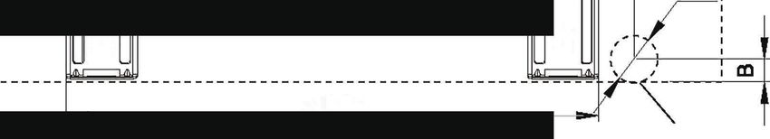
SAFETY INSTRUCTIONS
14.If the appliance is fixed wiring, the appliance must be fitted with means for
disconnection from the supply mains having a contact separation in all poles
that provide full disconnection under overvoltage category III conditions, and
these means must be incorporated in the fixed wiring in accordance with the
wiring rules.
15.If the supply cord is damaged, it must be replaced by the manufacturer, its
service agent or similarly qualified persons in order to avoid a hazard.
16.The appliance shall be installed in accordance with local electrical safety
regulations and National Electrical Codes(NEC).
17.The air conditioner must be installed by professional or qualified persons.
18.The appliance shall not be installed in the laundry.
19.Regarding to installation, please refer to section “Installation instructions”.
20.Regarding to maintenance, please refer to section “Care and Maintenance”.

                                       2
PREPARATION BEFORE USE
  Note

         When charging refrigerant into the system, make sure to charge in liquid state, if
         the refrigerant of the appliance is R410A.Otherwise, chemical composition of
         refrigerant (R410A) inside the system may change and thus affect performance
         of the air conditioner.
         According to the character of refrigerant (R410A,the value of GWP is 2088), the
         pressure of the tube is very high, so be sure to be careful when you install and
         repair the appliance.
         If the supply cord is damaged, it must be replaced by the manufacturer, its
         service agent or similarly qualified persons in order to avoid a hazard.
         The air conditioner must be installed by trained, qualified installers
         and service mechanics.
         The temperature of refrigerant circuit will be high, please keep the
         interconnection cable away from the copper tube.
  Preset
Before using the air conditioner, be sure to check and preset the following.
 Remote Control Presetting
Each time after the remote control is replaced with new batteries or is energized, remote control auto presetting
heat pump.If the air conditioner you purchased is a Cooling Only one, heat pump remote controller can also be
used.
 Back-light Function of Remote Control(optional)
Hold down any button on remote control to activate the back light. It automatically shuts off 10 seconds
later.
Note: Back-light is an optional function.
 Auto Restart Presetting
The air conditioner has an Auto-Restart function.

   Safeguarding the environment
This appliance is made of recyclable or re-usable material. Scrapping must be carried out in
compliance with local waste disposal regulations. Before scrapping it, make sure to cut off the
mains cord so that the appliance cannot be re-used.
For more detailed information on handling and recycling this product, contact your local authorities
who deal with the separate collection of rubbish or the shop where you bought the appliance.

SCRAPPING OF APPLIANCE

This marking indicates that this product should not be disposed
with other household wastes throughout the North America. To
 prevent possible harm to the environment or human health from
uncontrolled waste disposal, recycle it responsibly to promote
the sustainable reuse of material resources. To return your
used device, please use the return and collection systems or
contact the retailer where the product was purchased.
They can take this product for environmental safe recycling.

                                                        3
SAFETY PRECAUTIONS
Symbols in this Use and Care Manual are interpreted as shown below.
      Be sure not to do.                                                        Grounding is essential.

      Pay attention to such a situation.                                        Warning: Incorrect handling could
                                                                                cause a serious hazard, such as death,
                                                                                serious injury, etc.

                                                            ON                                            ON

      Use correct power supply in                          OFF
                                                                                                          OFF
      accordance with the rating plate
      requirement. Otherwise, serious
      faults or hazard may occur or a
      fire maybe break out.                      Keep the power supply circuit breaker
                                                 or plug from dirt. Connect the power           Do not use the power supply circuit
                                                 supply cord to it firmly and correctly,        breaker or pull off the plug to turn it off
                                                 lest an electric shock or a fire break out     during operation. This may cause a fire
                                                 due to insufficient contact.                   due to spark, etc.

  Do not knit, pull or press the power supply
  cord, lest the power supply cord be broken.    Never insert a stick or similar obstacle     It is harmful to your health if the cool air
  An electric shock or fire is probably caused   to the unit. Since the fan rotates at high   reaches you for a long time. It is advisable
  by a broken power supply cord.                 speed, this may cause an injury.             to let the air flow be deflected to all the room.

                          ON
                          OFF

            ON/OFF

            MODE        FAN

            SWING      SLEEP      SUPER

            SMART       IFEEL     DIMMER

           TIMER ON   TIMER OFF   CLOCK

  Turn off the appliance by remote control       Do not repair the appliance by yourself. Prevent the air flow from reaching the gas
  firstly before cutting off power supply if     If this is done incorrectly, it may cause an burners and stove.
  malfunction occurs.                            electric shock, etc.

                                                                                              It is the user's responsibility to make the
                                                                                              appliance be grounded according to
    Do not touch the operation buttons             Do not put any objects on the outdoor      local codes or ordinances by a licenced
    when your hands are wet.                       unit.                                      technician.

                                                                      4
INSTALLATION INSTRUCTIONS
Installation diagram
                                             Distance from ceiling
                                              should be over
  Distance from wall                          200 mm/7.9in
 should be over 50mm/2in

 Distance from the obstacle
 should be over 3.0m/10ft.                                                                                             Distance from the wall
                                                                                                                       should be over 50mm/2in

                  Distance from floor should be
                  over 2.4m/8ft.

                                                  Indoor unit A
 Above figure is only a simple presentation of the unit, it may not match the external appearance of the unit you purchased.

 Installation must be performed in accordance with the national wiring standards by authorized personnel only.

 Site Instructions
Site for Installing Indoor Unit
  1. Where there is no obstacle near the air outlet and air can be
  easily blown to every corner.
                                                                                                                             Indoor unit
  2. Where piping and wall hole can be easily arranged.
  3. Keep the required space from the unit to the ceiling and wall
  according to the installation diagram on previous page.
  4. Where the air filter can be easily removed.                                                                                            Pipe length is
  5. Keep the unit and remote controller 1m(3.28ft) or more apart                                                                           20 meters
                                                                                                                                            (65.4ft) Max.
  from television, radio etc.
                                                                                           be less than 10m (32.8ft)

  6. Keep as far as possible from fluorescent lamps.
  7. Do not put anything near the air inlet to obstruct it from air
                                                                                  Height should

                                                                                                                                                Outdoor unit
  absorption.
  8. Install on a wall that is strong enough to bear the weight of t
  he unit.
  9. Install in a place that will not increase operation noise and
  vibration.
                                                                                                                 Indoor unit is higher than outdoor unit
  10. Keep away from direct sunlight and heating sources. Do not place
   flammable materials or combustion apparatuses on top of the unit.
Installation of outdoor unit refers to the outdoor unit installation manual.

                                                              5
INSTALLATION INSTRUCTIONS
Suggested Tools

   In order to install your air-conditioner more conveniently and safely, you might use
 those special tools listed below.

                                    Standard Wrench

                                    Screw Driver

                                    Hex Keys or Allen Wrenches

                                    Adjustable/Crescent Wrench

                                    Torque wrench

                                    Drill & Drill Bits

                                    Manifold and Gauges

                                    Vacuum Pump

                                    Clamp on Amp Meter

                                    Level

                                    Work Gloves

                                    Safety Glasses

                                    Pipe Cutter

                                    Refrigerant Scale

                                    R410A Flaring Tool

                                    Micron Gauge

                                    Hole Saw

                                                     6
INSTALLATION INSTRUCTIONS
Indoor unit installation
1. Installing the Mounting Plate
FOR the Ordinary Mounting Plate
Decide an installing location for the mounting plate according to the indoor unit location and piping
direction.
Note: it is recommended to install screw anchors for sheet rock, concrete block, brick and such type of wall.
Keep the mounting. plate horizontal with a horizontal level or dropping line.
Mark the center of the indoor unit on mounting plate for future reference.
Note: the center of the mounting bracket may be not the center of the indoor unit.
Tapping mounting plate to the wall with a minimum of five screws, evenly spaced to properly support
indoor unit weight.
Tapping screw
Mounting plate
Note: The shape of your mounting plate may be different from the one above, but the installation method is similar.
Note: As the above figure shown, the six holes matched with tapping screw on the mounting plate must be used to
fix the mounting plate, the others are prepared.
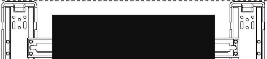
MOUNTING BRACKET DIAGRAMS AND DIMENSIONS (Recommended)
Indoor unit outline
200mm/7.9in or more to ceiling
50mm/2in
or more to wall
50mm/2in
or more to wall
Pipe hole
For 738 Series Model, WIDTH:522mm/20.6in
For 808 Series Model, WIDTH:592mm/23.3in
7INSTALLATION INSTRUCTIONS
FOR the Ordinary Mounting Plate
MOUNTING BRACKET DIAGRAMS AND DIMENSIONS (Recommended)
Indoor unit outline
200mm/7.9in or more to ceiling
50mm/2in
or more to wall
50mm/2in
or more to wall
Pipe hole
For 908/1080 Series Model, WIDTH: 629mm/24.8in
Indoor unit outline
200mm/7.9in or more to ceiling
50mm/2in 50mm/2in
or more to wall or more to wall
Pipe hole
For 1280 Series Model, WIDTH:820mm/32.3in
8INSTALLATION INSTRUCTIONS
Indoor unit installation
FOR the Wooden Wall Mounting Plate
Decide an installing location for the mounting plate according to the indoor unit location and piping
direction.
Note: it is recommended to install screw anchors for sheet rock, concrete block, brick and such type of wall.
Keep the mounting. plate horizontal with a horizontal level or dropping line.
Mark the center of the indoor unit on mounting plate for future reference.
Note: the center of the mounting bracket may be not the center of the indoor unit.
Tapping mounting plate to the wall with a minimum of five screws, evenly spaced to properly support
indoor unit weight.
Note: The shape of your mounting plate may be different from the one above, but the installation method is similar.
Note: As the above figure shown, the six holes matched with tapping screw on the mounting plate must be used to
fix the mounting plate, the others are prepared.
MOUNTING BRACKET DIAGRAMS AND DIMENSIONS (Recommended)
9INSTALLATION INSTRUCTIONS
FOR the Wooden Wall Mounting Plate
MOUNTING BRACKET DIAGRAMS AND DIMENSIONS (Recommended)
Indoor unit outline
200mm/7.9in or more to ceiling
50mm/2in 50mm/2in
or more to wall or more to wall
Pipe hole
For 1280 Series Model, WIDTH:820mm/32.3in
10REMOTE CONTROL
INSTALLATION INSTRUCTIONS
Indoor unit installation
2. Drill a Hole in wall for interconnecting Piping, Drain & Wiring
Decide the position of the hole for piping according to the Wall hole sleeve
location of mounting plate. ( hard polythene tube
Outdoor
Indoor
Drill a hole in the wall. The hole should tilt a little prepared by user)
downward toward outside.
Install a sleeve through the wall hole to keep the wall
tidy and clean.
5mm
0.2in
(tilt downward)
Table of Wall Hole Mounting size per Unit Size
Size A Size B Size C
Unit Model
mm/in mm/in mm/in
738 Series 68/2.68 33/1.3 70/2.7
808 Series 70/2.75 35/1.38 70/2.7
908 Series 137/5.4 40/1.57 70/2.7
1080 Series 170/6.7 40/1.57 70/2.7
1280 Series 64/2.52 41.2/1.62 70/2.7
3. Piping and Drain Hose Connections to Indoor Unit
Put the piping (liquid and gas pipe) and cables through the wall hole from outside or put them through
from inside after indoor piping and cables connection is complete to connect to the outdoor unit.
Decide whether to saw the unloading piece off in accordance with the piping direction.(as shown below)
Piping direction
Drain
Trough hole Drainage
structure
Unloading
piece
4 Rubber plug
1
3
Saw the unloading piece
off along the trough Note: When installing the pipe at the directions
2 1,2 or 4, saw the corresponding unloading piece
off the indoor unit base.
After connecting the piping , install the drain hose. Then connect the power cords. After connecting,
wrap the piping, cords and drain hose together with thermal insulation materials.
Note: Both sides drainage structure is standard. For both sides drainage structure, it can be chosen for right, left or both
sides drainage connection. If choosing both sides drainage connection, another proper drain hose is needed as there is
only one drain hose offered by factory. If choosing one side drainage connection, make sure the drain hole on the other
side is well plugged.
11INSTALLATION INSTRUCTIONS
Indoor unit installation
Piping Joints Thermal Insulation:
Wrap the piping joints with thermal
insulation materials and then wrap
with a vinyl tape. wrapped with vinyl type
Thermal insulation
Piping Thermal Insulation:
Large pipe Thermal insulation
a. Place the drain hose under the piping. tube
b. Insulation material uses polythene foam over 6mm in thickness. Power cord
Note: Drain hose is prepared by user.
Do not arrange the drain pipe in a way that leaves it twisted, sticking Small
out or waving around. Do not immerse the end of it in water. pipe
If an extension drain hose is connected to the drain pipe, make sure
to insulated when passing along the indoor unit.
Drain hose
(prepared by user)
When the piping is directed to the right, piping, power
Cord and drain pipe should be thermal insulated and
fixed onto the back of the unit with a piping fixer.
Insert here
large large
pipe pipe
drain small drain small
hose pipe hose pipe
Piping fixer Hook here
Base Piping fixer Base Base
A. Insert the pipe fixer to the slot. B. Press to hook the pipe fixer onto the base.
Piping Connection:
a.Before unscrewing the big and the small sealing caps, press the small
sealing cap with the finger until the exhaust noise stops, and then loosen
the finger.
b. Connect indoor unit pipes with two wrenches. Pay special attention
to the allowed torque as shown below to prevent the pipes, connectors
and flare nuts from being deformed and damaged.
c. Pre-tighten them with fingers at first, then use the wrenches.
If you don't hear the exhaust noise, please contact with the merchant.
Model Pipe size Torque Nut width Min.thickness
9K-18K Liquid Side (φ6 or 1/4) 15~20N·m or 11~15ft-lbs 17 or 5/8 0.5 or 0.02
24K-36K Liquid Side (φ9.53 or 3/8) 30~35N·m or 22~26ft-lbs 22 or 7/8 0.6 or 0.024
9K-12K Gas Side (φ9.53 or 3/8 ) 30~35N·m or 22~26ft-lbs 22 or 7/8 0.6 or 0.024
18K Gas Side (φ12 or 1/2 ) 50~55N·m or 37~41ft-lbs 24 or 0.94 0.6 or 0.024
24K-36K Gas Side (φ16 or 5/8) 60~65N·m or 44~48ft-lbs 27 or 1.1 0.6 or 0.024
36K Gas Side (φ19 or 3/4) 70~75N·m or 52~55ft-lbs 32 or 1.26 1.0 or 0.039
NOTE:
Dimensions are in “mm or inch” unless otherwise stated in the table.
12INSTALLATION INSTRUCTIONS
If the diameter of connection pipe does not match the port size of outdoor unit, select
proper different-diameter joints in the accessory according to the following table.
Name Quantity Purpose
Change pipe diameter from
1
1/4(6.35) to 3/8(9.52)
Change pipe diameter from Outdoor unit Different-diameter joint indoor unit
1
3/8(9.52) to 5/8(15.88)
Change pipe diameter from Connect pipes using different-diameter joint
1
3/8(9.52) to 1/2(12.7) mm
Power and Wiring Front panel
Terminal (inside)
Connecting of the Cable
Indoor Unit
Connect the power cord to the indoor unit by connecting
the wires to the terminals on the control board individually Cabinet
in accordance with the outdoor unit connection.
Indoor unit
Chassis
Note: For some models, it is necessary to remove the cabinet to
connect to the indoor unit terminal. The figures in this manual are based on the external
view of a standard model. Consequently, the shape
may differ from that of the air conditioner you have
selected.
Caution:
1. Never fail to have an individual power circuit specifically for the air conditioner. As for the method of
wiring, refer to the circuit diagram posted on the inside of the access door .
2. Comfirm that the cable thickness is as specified in the power source specification.
3. Check the wires and make sure that they are all tightly fastened after cable connection.
4. Be sure to install an earth leakage circuit breaker in wet or moist areas.
Cable Specifications
capacity(Btuh) Power cord Power connecting cord
Normal cross- Normal cross-
Type Type
sectional areas sectional areas
9K-12K(208/230V) SJ TW 3X16 AWG SJ TW 4X18 AWG
18K(208/230V) SJ TW 3X14 AWG SJ TW 4X18 AWG
24K-36K(208/230V) SJ TW 3X12 AWG SJ TW 4X18 AWG
9K,12K(115V) SJ TW 3X14 AWG SJ TW 4X18 AWG
Attention:
The plug must be accessible even after the installation of the appliance in case there is a need
to disconnect it. If not possible, connect appliance to a double-pole switching device with
contact separation of at least 3 mm placed in an accessible position even after installation.
13INSTALLATION INSTRUCTIONS
Wiring diagram
Make sure that the color of the wires in the outdoor unit and terminal No. are the same as those
of the indoor unit.
Warning: Before obtaining access to terminals, all supply circuits must
be disconnected.
(1) 208/230V
For the mono split
Terminal
Indoor unit Outdoor unit
1(N) 2(L) 3(SI) Terminal Terminal
Power supply
GN
WHT
L1
Gree BLK
n Power connecting cord L2
White White
1(N) ac
k Bl
ac 1(N)
Bl Re k
d d
2(L) R
e 2(L)
Connecting
Gree
cable to outdoor unit 3(SI) 3(SI)
n
For the multi interver
Terminal Indoor unit Outdoor unit
Terminal Terminal
1(N) 2(L) 3(SI)
YE/G
N Power connecting cord Black 4(SI)
Blue Blue
1(N) ow
n Br
ow 2(N)
Br ck n
2(L) la 1(L)
B
YE/G
3(SI)
Connecting
N
cable to outdoor unit
The diagram is reference only, and the actual terminal shall prevail.
14INSTALLATION INSTRUCTIONS
Wiring diagram
Make sure that the color of the wires in the outdoor unit and terminal No. are the same as those
of the indoor unit.
Warning: Before obtaining access to terminals, all supply circuits must
be disconnected.
(2) 115V
For the mono split
Terminal
Indoor unit Outdoor unit
1(N) 2(L) 3(SI) Terminal Terminal
Power supply
GN
WHT
N
Gree BLK
n Power connecting cord L
White White
1(N) ac
k Bl
ac 1(N)
Bl Re k
d d
2(L) R
e 2(L)
Connecting
Gree
cable to outdoor unit
3(SI) 3(SI)
n
For the multi interver
( Currently unavailable. )
The diagram is reference only, and the actual terminal shall prevail.
15INSTALLATION INSTRUCTIONS
Start-up
Test Operation
Perform test operation after completing gas leak and electrical safety check.
1.Turn on electrical disconnect to outdoor unit.
2.Push the “ON/OFF” button on Remote Controller to begin testing.
3.Push MODE button, select COOLING, HEATING, FAN mode to confirm all functions.
System Checks
1.Conceal refrigerant pipes where possible.
2.Make sure drain hose slopes downward along entire length.
3.Ensure all refrigerant pipes and connections are properly insulated.
4.Fasten pipes to outside wall, when possible.
5.Seal and weatherproof wall hole which the interconnecting wires and refrigerant pipes pass through.
Indoor Unit
1.Do all Remote controller’s buttons function properly?
2.Do the display panel lights work properly?
3.Does the swing louver function properly?
4.Does the drain work?
Outdoor Unit
1.Push the mode button to COOL and adjust the room setting to 61 ℉(16℃) deg. wait up to 3 minutes
from compressor time guard. Does compressor and outdoor fan turn on in cooling mode?
2.Push the mode button to HEAT and adjust the room setting to 85 ℉(30℃) deg. wait up to 3 minutes
for compressor time guard. Does compressor and outdoor fan turn on in heat mode?
16CARE AND MAINTENANCE
Front panel maintenance Air filter maintenance
1.Turn off the air conditioner first.
2.Cut off the power supply by moving the
the power plug.
It is necessary to clean the air filter
after using it for about 200 hours.
Clean it as follows:
a Stop the appliance and remove
the air filter.
Grasp position "a" and
pull outward to remove the
front panel. a
1
2
3
Wipe with a soft
1.Open the front panel.
and dry cloth.
2.Press the handle of the filter gently
Use soft moisture cloth Use a dry and from the front.
to clean if the front panel soft cloth to 3. Grasp the handle and slide out the filter.
clean it.
is very dirty.
Never use volatile substance
such as gasoline or polishing Clean and reinstall the air filter.
powder to clean the appliance.
If the dirt is conspicuous,
wash it with a solution of
detergent in lukewarm water.
After cleaning, dry well in
shade.
Never sprinkle water onto the
indoor unit
Dangerous!
Electric Close the front panel again.
shock!
Reinstall and shut the front panel. Clean the air filter every two weeks
Reinstall and shut the front panel by if the air conditioner operates in an
pressing position "b" downward. extremely dusty environment.
b b
17PROTECTION
Operating condition
Operating temperature
Temperature Cooling operation Heating operation Drying operation
max 90 32 81 27 90 32
Indoor
temperature
min 70 (21 45 (7 64 18
max 115 (46 75 (24 ) 115 (46
Outdoor
temperature min note 5 (-15 70 (21
NOTE:
*Optimum performance will be achieved within these operating temperature. If air conditioner is used outside of
the above conditions, the protective device may trip and stop the appliance.
*For Tropical (T3) Climate condition models, the outdoor max temperature is 131 (55 instead of 115 (46 .
*For some models, can keep cooling at 5 (-15 outdoor ambient via unique design. Normally, optimum cooling
performance will be achieved above 70 21 . Please consult the merchant to get more information.
*For some models, can keep heating at 5 (-15 outdoor ambient , some models heat at -4 (-20 outdoor ambient
even heat at lower outdoor ambient
The temperature of some products is allowed beyond the range. In specific situation, please consult the
merchant. When relative humidity is above 80%, if the air conditioner runs in COOLING or DRY mode with door
or window opened for a long time, dew may drip down from the outlet.
Noise pollution
Install the air conditioner at a place that can bear its weight in order to operate more quietly.
Install the outdoor unit at a place where the air discharged and the operation noise would not annoy
your neighbors.
Do not place any obstacles in front of the air outlet of the outdoor unit lest it increases the noise level.
Features of protector
1. The protective device will work at following cases.
Restarting the unit at once after operation stops or changing mode during operation, you need to wait for
3 minutes.
Connect to power supply and turn on the unit at once, it may start 20 seconds later.
2. If all operation has stopped, press ON/OFF button again to restart, Timer should be set again if it has
been canceled.
Features of HEATING mode
Preheat
At the beginning of the HEATING operation, the airflow from the indoor unit is discharged 2-5 minutes later.
Defrost
In HEATING operation the appliance will defrost (de-ice) automatically to raise efficiency.
This procedure usually lasts 2-10 minutes. During defrosting, fans stop operation.
After defrosting completes, it returns to HEATING mode automatically.
Note: Heating is NOT available for cooling only air conditioner models.
18ENERGY SAVING TIPS
1.Relaxing room temperature at night is OK: During the nighttime hours you
don't require the same level of conscious cooling or heating. Try using Sleep
mode to gradually relax room temperature and allow the unit to run less and save
energy.
2.Curtains and shades: In the summer, you need to block the effects of the sun.
Close window curtains and shades on the south and west side of your home to
help block solar heat. In winter, the sun is your friend. Open curtains and shades
to allow solar heat into your room.
3.Close doors: If you don't need to heat and cool your whole home, confine the
heating and cooling to one room by closing doors. Limit the space you're heating
and cooling to specified capability of the unit.
4.Service the unit: Some basic maintenance might be all you need. The outdoor
unit will greatly benefit from a good hosing out, especially in treed areas where
seeds and other debris can stick to coil fins and make the unit work harder!
5.Rearrange the room: Furniture that obstructs airflow means you could be
heating and cooling the back of a chair or the front of a sofa instead of the actual
living space. Use the swing louvers to help direct the air in the right direction for
the room; remove or rearrange obstacles blocking airflow.
6.Try 75 degrees: 75℉(24℃) is a good point for an air conditioner to run at its
optimal performance level. Even a 1-degree change in temperature can make
your unit use more energy!
7.Lighting: Turning lights off can help reduce your heat. Each light bulb is a tiny
heater. Your air conditioner must waste energy overcoming the heat from your
lights to reach and hold your desired room temperature.
8.Is anyone home? If possible, while you're away turn your unit to Auto mode and
make sure windows and drapes are closed. Although the room temperature will be
uncomfortable for a few minutes when you come home, the unit will have the room
back to your desired temperature in no time.
9.Don't forget the fan: The fan is much like a car. The faster it runs, the more
energy is consumed. Sometimes we need the car to go fast, but slow is good
enough most of the time. Try saving money by using the comfortable quiet low fan
speed as much as possible.
19TROUBLESHOOTING
The following cases may not always be a malfunction, please check it before asking for service.
Trouble Analysis
If the protector trip or fuse is blown.
Please wait for 3 minutes and start again,
Does not run protector device may be preventing unit to work.
.If batteries in the remote controller exhausted.
If the plug is not properly plugged.
No cooling or Is the air filter dirty?
heating air Are the intakes and outlets of the air
conditioner blocked?
Is the temperature set properly?
Ineffective control If strong interference(from excessive static
electricity discharge, power supply voltage
abnormality)presents, operation will be
abnormal. At this time, disconnect from the
power supply and connect back 2-3 seconds later.
Changing mode during operation, 3 minutes
Does not operate will delay.
immediately
don't run
This odor may come from another source
such as furniture, cigarette etc, which is
Peculiar odor sucked in the unit and blows out with the air.
A sound of Caused by the flow of refrigerant in the
flowing water air conditioner, not a trouble.
Defrosting sound in heating mode.
The sound may be generated by the expansion
Cracking sound is or contraction of the front panel due to change
heard of temperature.
Spray mist from Mist appears when the room air becomes
the outlet very cold because of cool air discharged
from indoor unit during COOLING or DRY
operation mode.
The running indicator flashes on constantly, The unit is shifting from heating mode to defrost.
and indoor fan stops. The indicator will flash within twelve minutes and
returns to heating mode.
cooling dry heating fan
Mode interfere cooling normal
For the reason that all indoor units use one outdoor dry mode interfere
unit, outdoor unit can only run with same mode heating
(cooling or heating),so,when the mode you set is fan
different from the mode that outdoor is running with, outdoor unit always run with the mode of first indoor unit that turned on.
mode interfere occurs. Following shows the mode when the setting mode of following indoor unit is interfered with it, 3 beeps
would be heard, and the indoor unit interfered with the normal running units
interfere scene. would turn off automatically.
20IDENTIFICATION OF PARTS
Indoor unit
4
3
2
Part Name
1
1. Remote Controller
ON
OF
F
ON
2. Air Filter
/O
FF
MO
DE
SW FA
IN G N
SM S LE
AR EP
T
SU
TI M IF E PE
ER EL R
ON
TI M D IM
ER ME
O FF R
C LO
CK
3. Horizontal Louvers
4. Front Panel
5. Pipes and Power
5 Connection Cord
Outdoor unit 6. Drain Hose
6
The figures in this manual are based on the external view of a standard model.
Consequently, the shape may differ from that of the air conditioner you have selected.
21DISPLAY INTRODUCTION
Temperature indicator 1
Display set temperature.
It shows FC after 200 hours of usage as reminder to clean the filter.
After filter cleaning press the filter reset button located on the indoor unit behind the front
panel in order to reset the display.(optional)
Running indicator 2
It lights up when the AC is running.
It flashes during defrosting.
Timer indicator 3
It lights up during set time.
Sleep indicator 4
It lights up in sleep mode.
Compressor indicator 5
It lights up when the compressor is on.
Mode indicator 6
Heating displays orange,others display white
Fan speed indicator 7
Signal Receptor 8
Smart WIFI indicator 9
It lights up during WIFI is on.
NANOE indicator 10
It lights up in NANOE mode.
VQ/TE/TF/DA/DG(Middle)/DH/DL(Right side) series
3
3 5 1 2 4
8
The symbols may be different from these models, but the functions are similar.
22DISPLAY INTRODUCTION
VT series
3 5 1 2 4
8
DG(Right side) series
1 2 3 4 5 8
DE series DF series
3
1 8 5
1
2
4
3 5 2 4 8
The symbols may be different from these models, but the functions are similar.
23DISPLAY INTRODUCTION
TA series TQ/TR series
1 8
optional
9 3
8
2 4
3
optional
1
TD/TG/TS/TT/DB/DC/DH(Hidden display)/ SC series
DL(Middle)/DJ/DK/DN series 1
8 1
3 2 4 6 7
2
TL series
1
3 2 4
The symbols may be different from these models, but the functions are similar.
24DISPLAY INTRODUCTION
QA/QB series
1
optional
10 9
2
optional
(TD/TL/TJ/TQ/TR/TS/TT/TP/TM/ (CA/CB)(Right side) series
DB/DC/DL/DJ/DK/DX)(Only 88)/
(CA/CB)(Middle) series
1 2
Emergency button A QA/QB series
A A
ON/OFF To let the AC run or stop by pressing the button.
The symbols may be different from these models, but the functions are similar.
25Emerson Quiet Kool Co. Ltd. 120 US- 46 Parsippany -Troy Hills, NJ 07054 Toll Free 1-888-493-0305 Version Update:--2021.5.0
Free Match Multi Zone Outdoor Units

User Manual
Model No.: EAC2H18R2C
           EAC4H36R2C
           EAC3H24R2C
           EAC5H42R2C

Thank you very much for purchasing our air conditioner. Please read this owen's manual carefully before
using your air conditioner.
Instrucciones de seguridad 1 Preparación antes del uso 3 Precauciones de seguridad 4 Instrucciones de instalación 5 Cuidado y mantenimiento 17 Protección 18 Consejos de ahorro de energía 19 Solución de problemas 20 Identificación de piezas 21 Introducción de visualización 22 THANK YOU Congratulations on your purchase and welcome to the Family. Your new Air Conditioner combines high-efficiency operation with portable convenience. By following the operating and care instructions in this manual, your air conditioner will provide you with many years of reliable service. Please visit our website www.eqkhvac.com For any questions or Technical Support, please contact us by mail info@geektechnology.com or by phone 1-888-493-0305.
INSTRUCCIONES DE SEGURIDAD
1. Para garantizar que la unidad funcione con normalidad, lea atentamente el manual antes de
realizar la instalación y realícela en estricta conformidad con este manual.
2. No deje que entre aire en el sistema de refrigeración o descargue el refrigerante cuando traslade
el climatizador.
3. Conecte adecuadamente el climatizador a tierra.
4. Compruebe detenidamente los cables de conexión y las tuberías, y asegúrese de que las
conexiones sean correctas y firmes antes de conectar la alimentación del climatizador.
5. Debe disponer de un interruptor neumático.
6. Después de la instalación, el consumidor debe operar correctamente el climatizador en
conformidad con este manual, disponer de material de almacenamiento adecuado para realizar el
mantenimiento y el traslado del climatizador en el futuro.
7. Fusible de la unidad:

             Modelo                      Fusible de la unidad interior   Fusible de la unidad exterior

           9K(115V)                     T 3.15A o T 5A 250V                     T 25A 250V
          12K(115V)                     T 3.15A o T 5A 250V                     T 25A 250V
     9K-12K(208/230V)                   T 3.15A o T 5A 250V                     T 15A 250V
       18K(208/230V)                     T 3.15A o T 5A 250V                    T 20A 250V
     24K-36K(208/230V)                   T 3.15A o T 5A 250V                    T 30A 250V

8. Se debe incorporar un dispositivo de corriente residual (RCD) con una potencia superior a
10 mA en el cableado fijo en conformidad con la normativa nacional.
9. Advertencia: Riesgo de descarga eléctrica que podría causar lesiones o muerte:
Desconecte toda alimentación eléctrica remota antes de revisar el aparato.
10. La longitud óptima de la tubería de conexión entre la unidad interior y la unidad exterior
es de menos de 7,5 metros (24,6 pies). Si la distancia es mayor, afectará a la eficacia del
climatizador.
11. Este aparato no ha sido diseñado para que lo utilicen personas (incluidos niños) con
capacidades físicas, sensoriales o mentales reducidas, o con falta de experiencia o
conocimientos, a menos que estén supervisados o reciban instrucciones acerca del uso del
aparato por parte de una persona responsable de su seguridad. Los niños deben estar
supervisados para garantizar que no jueguen con el aparato.
12. Este aparato puede ser utilizado por niños mayores de 8 años y por personas con
capacidades físicas, sensoriales o mentales reducidas o falta de experiencia y
conocimientos si están supervisados o han recibido instrucciones relativas al uso del
aparato de forma segura y si comprender los riesgos asociados. Los niños no deben jugar
con el aparato. La limpieza y el mantenimiento no deben realizarlos niños sin supervisión.
13. Las pilas del mando a distancia deben reciclarse o eliminarse adecuadamente.               .
Eliminación de las pilas usadas: deseche las pilas como residuos municipales clasificados
en un punto de recogida accesible.

                                                1
INSTRUCCIONES DE SEGURIDAD
14.Si el aparato tiene cableado fijo, debe disponer de un medio de desconexión de
la alimentación eléctrica con una separación del contacto en todos los polos que
proporcione una desconexión completa en condiciones de sobretensión de categoría
III y dichos medios deben estar incorporados en el cableado fijo de acuerdo con las
normas de cableado.
15.Si el cable de alimentación está dañado, debe sustituirlo el fabricante, su agente
de mantenimiento o personas cualificadas similares para evitar riesgos.
16.El aparato debe instalarse en conformidad con la normativa de seguridad
eléctrica local y el National Electric Code (NEC).
17.La instalación del climatizador debe realizarla una persona profesional o
cualificada.
18.No debe instalarse el aparato en una lavandería.
19.Para ver más información acerca de la instalación, consulte la sección
“Instrucciones de la instalación”.
20.Para ver más información acerca del mantenimiento, consulte la sección
“Cuidado y mantenimiento”.
2PREPARACIÓN ANTES DEL USO
Nota
Cuando cargue refrigerante en el sistema, asegúrese de que que esté en
estado líquido si el refrigerante del aparato es R410A. De lo contrario, la
composición química del refrigerante (R410A) en el interior del sistema podría
cambiar y afectar al rendimiento del climatizador.
De acuerdo con el carácter del refrigerante (R410A, el valor de GWP es 2088),
la presión del tubo es muy elevada, así que sea cauteloso cuando instale y
repare el aparato.
Si el cable de alimentación está dañado, debe sustituirlo el fabricante, su agente
de mantenimiento o personas cualificadas similares para evitar riesgos.
Solo instaladores y mecánicos de servicio cualificados y formados
deben instalar el climatizador.
La temperatura del circuito de refrigerante será alta, mantenga el cable
de conexión de las unidades apartado de las tuberías de cobre.
Preajuste
Antes de utilizar el climatizador, compruebe y realice el preajuste de los siguientes elementos.
Preajuste del mando a distancia
Cada vez que se sustituyan las pilas del mando a distancia o se cargue, el mando a distancia se ajusta
automáticamente en bomba de calor. Si el climatizador que ha comprado es solo de enfriamiento, también
puede usar el mando a distancia de uno de bomba de calor.
Función de retroiluminación del mando a distancia (opcional)
Mantenga pulsado cualquier botón del mando a distancia para activar la retroiluminación. Se apagará
automáticamente 10 segundos después.
Nota: La retroiluminación es una función opcional.
Preajuste de reinicio automático
El climatizador tiene una opción de reinicio automático.
Proteger el entorno
Este aparato está fabricado con materiales reciclables o reutilizables. El desguace del mismo debe
realizarse siguiendo las normativas locales de eliminación de residuos. Antes de desguazarlo,
asegúrese de cortar los cables eléctricos de forma que no pueda reutilizarse el aparato.
Para obtener información más detallada de la manipulación y el reciclaje de este producto, póngase
en contacto con las autoridades locales que gestionen la recogida separada de residuos o con la
tienda donde compró el aparato.
Esta marca indica que no se debe eliminar el producto con otros
residuos doméstico en la UE. Para evitar posibles daños al medio
ambiente o a la salud debidos a la eliminación descontrolada de
residuos, recíclelo de forma responsable para fomentar la
reutilización sostenible de los recursos materiales. Para devolver su
dispositivo usado, utilice los sistemas de devolución y recogida o
póngase en contacto con el distribuidor donde compró el producto.
Ellos pueden hacerse cargo del producto para reciclarlo de forma
segura para el medio ambiente.
3PRECAUCIONES DE SEGURIDAD
Los símbolos de este manual de uso y mantenimiento se interpretan de la
siguiente manera.
No hacer bajo ningún concepto. La conexión a tierra es fundamental.
Preste atención a esta situación. Advertencia: Una manipulación
incorrecta puede provocar riesgos
graves, como muerte, lesiones
graves, etc.
Encendido
Encendido
Utilice una alimentación Apagado Apagado
eléctrica que se corresponda
con el requisito nominal del
equipo. De lo contrario, podrían
ocurrir fallos graves o un Evite que el interruptor o el enchufe de No utilice el interruptor de la alimentación
incendio. alimentación eléctrica se ensucien. Conecte eléctrica ni estire del enchufe para apagarlo
el cable eléctrico con firmeza y
correctamente, ya que podría provocar durante el funcionamiento. Esto podría
descargas eléctricas o incendios por un provocar un incendio causado por chispas,
contacto insuficiente. etc.
No doble, estire ni aplaste el cable Nunca inserte palos ni objetos similares Estar expuesto al aire frío durante mucho
eléctrico, ya que podría romperse. Los en la unidad. Debido a la alta velocidad tiempo es perjudicial para la salud,. Se
cables eléctricos rotos podrían provocar de giro de los ventiladores, podría recomienda permitir que el flujo de aire se
una descarga eléctrica o un incendio. causar lesiones. distribuya por toda la habitación.
ON
OFF
ON/OFF
MODE FAN
SWING SLEEP SUPER
SMART IFEEL DIMMER
TIMER ON TIMER OFF CLOCK
Primero apague el aparato con el
mando a distancia antes de No repare el aparato usted mismo. Si se Evite que el flujo de aire llegue a los
desconectar la alimentación eléctrica si hace de forma incorrecta, podría quemadores de gas y a la estufa.
hubiera un mal funcionamiento. provocar una descarga eléctrica, etc.
Es responsabilidad del usuario
asegurarse de que un técnico
No toque los botones de No coloque objetos en la unidad cualificado realice la conexión a tierra
funcionamiento con las manos exterior. del aparato en conformidad con los
mojadas. códigos u ordenanzas locales.
4INSTRUCCIONES DE INSTALACIÓN
Diagrama de instalación
La distancia del techo
debería ser más de
La distancia de la 200mm/7,9pulgadas
pared debería ser
más de 50mm/2pulgadas
La distancia desde el obstáculo
debería ser de más de 3,0 m/10 La distancia de la pared debería
pies. ser más de 50mm/2pulgadas
La distancia del suelo
debería ser más de 2,4m/8 pies.
Unidad interna A
Instrucciones del sitio
Lugar de instalación de la unidad interior:
Donde no haya obstáculos cerca de la salida de aire y el aire pueda
llegar fácilmente a todos los rincones.
Donde pueda realizarse fácilmente un orificio en la pared. Unidad interior
Mantenga la separación requerida desde la unidad hasta el techo y
la pared de acuerdo con el diagrama de instalación de la página
anterior.
Donde el filtro de aire pueda sustituirse fácilmente. La longitud de la
tubería es de 20
Mantenga la unidad y el mando a 1 m (3,28 pies) de distancia o metros (65,4 pies)
más respecto a televisores, radios, etc.
inferior a 10 m (32,8 pies)
máx.
La altura debe ser
Tan alejada como sea posible de lámparas fluorescentes.
No coloque nada cerca de la entrada de aire que obstruya la
absorción de aire. Unidad exterior
Instálela en una pared lo bastante fuerte para soportar el peso de la
unidad.
Instálela en un lugar que no incremente el ruido y las vibraciones
del funcionamiento.
Manténgala apartada de la luz solar directa y de fuentes de calor.
La unidad interior debe estar más
No coloque materiales inflamables ni aparatos de combustión sobre elevada que la unidad exterior.
la unidad.
La instalación de la unidad interna se refiere al manual de instalación de la unidad externa.
5INSTRUCCIONES DE INSTALACIÓN
Herramientas sugeridas
Para instalar el climatizador de forma más conveniente y segura, puede utilizar las
herramientas especiales descritas a continuación.
Llave inglesa estándar
Destornillador
Llaves hexagonales o llaves Allen
Llave ajustable/llave de media luna
Llave dinamométrica
Taladro y brocas de taladro
Colector y manómetros
Bomba de vacío
Pinza amperimétrica
Nivel
Guantes de trabajo
Gafas de seguridad
Cortador de tuberías
Escala de refrigerante
Herramienta de ensanchamiento R410A
Indicador de micras
Sierra perforadora
6INSTRUCCIONES DE INSTALACIÓN
1.Instalación de la placa de montaje
Para la placa de montaje
Decida una ubicación de instalación para la placa de montaje conforme a la ubicación de la
Nota: ladrillos y tipos similares de paredes.
Mantenga la placa de montaje horizontal con una regla.
Marque el centro de la unidad interna en la placa de montaje para futuras referencias.
Nota:El centro del soporte de montaje no debe ser el centro de la unidad interior.
Atornille la placa de montaje en la pared con cinco tornillos como mínimo, separados
Tornillo autorroscante
Placa de montaje
Nota: La forma de su placa de montaje podría ser diferente a la mostrada aquí, pero el método de instalación es similar.
Nota: Como se muestra en la imagen de arriba, se deben utilizar los seis orificios que coinciden con el tornillo
autorroscante en la placa de montaje para fijar la placa, los otros están preparados
DIAGRAMAS Y DIMENSIONES (recomendadas) DE LA PLACA DE MONTAJE
Esquema de la unidad interior
200 mm/7,9 pulgadas o más respecto al techo
50 mm/2 pulgadas o más
respecto a la pared
50 mm/2 pulgadas o
más respecto a la pared
Ancho
Orificio para tubería
Para el modelo Serie 738, ancho:522mm/20.6 pulgadas
Para el modelo Serie 808, ancho:592mm/23.3 pulgadas
7INSTRUCCIONES DE INSTALACIÓN
Para la placa de montaje ordinaria
DIAGRAMAS Y DIMENSIONES (recomendadas) DE LA PLACA DE MONTAJE
Esquema de la unidad interior
200 mm/7,9 pulgadas o más respecto al techo
50 mm/2
pulgadas o más 50 mm/2 pulgadas o
respecto a la más respecto a la pared
pared
Orificio para tubería
Para el modelo Serie 908/1080, ancho:629mm/24.8 pulgadas
Esquema de la unidad interior
200 mm/7,9 pulgadas o más respecto al techo
50 mm/2
pulgadas o más 50 mm/2 pulgadas o
respecto a la más respecto a la pared
pared
Orificio para tubería
Para el modelo Serie 1280, ancho:820mm/32.3 pulgadas
8INSTRUCCIONES DE INSTALACIÓN
Instalación de la unidad interna
Para la placa de montaje en la pared de madera
Decida una ubicación de instalación para la placa de montaje conforme a la ubicación de la
Nota:
Marque el centro de la unidad interna en la placa de montaje para futuras referencias.
Nota:El centro del soporte de montaje no debe ser el centro de la unidad interior.
Atornille la placa de montaje en la pared con cinco tornillos como mínimo, separados
Tornillo
Tornillo autorroscante
autorroscante
Placa de montaje Placa de montaje
Pared de hormigón / ladrillo Pared de madera
Nota: La forma de su placa de montaje podría ser diferente a la mostrada aquí, pero el método de instalación es similar.
Nota: Como se muestra en la imagen de arriba, se deben utilizar los seis orificios que coinciden con el tornillo
autorroscante en la placa de montaje para fijar la placa, los otros están preparados
DIAGRAMAS Y DIMENSIONES (recomendadas) DE LA PLACA DE MONTAJE
Esquema de la unidad interior
200 mm/7,9 pulgadas o más respecto al techo
50 mm/2 pulgadas o más
respecto a la pared
50 mm/2 pulgadas o
más respecto a la pared
Orificio para tubería
Para el modelo Serie 738, ancho:522mm/20.6 pulgadas
Para el modelo Serie 808, ancho:592mm/23.3 pulgadas
9INSTRUCCIONES DE INSTALACIÓN
Para la placa de montaje ordinaria
DIAGRAMAS Y DIMENSIONES (recomendadas) DE LA PLACA DE MONTAJE
Esquema de la unidad interior
200 mm/7,9 pulgadas o más respecto al techo
50 mm/2
pulgadas o más 50 mm/2 pulgadas o
respecto a la más respecto a la pared
pared
Orificio para tubería
Para el modelo Serie 908/1080, ancho:629mm/24.8 pulgadas
Esquema de la unidad interior
200 mm/7,9 pulgadas o más respecto al techo
50 mm/2
pulgadas o más 50 mm/2 pulgadas o
respecto a la más respecto a la pared
pared
Orificio para tubería
Para el modelo Serie 1280, ancho:820mm/32.3 pulgadas
10REMOTE CONTROL
INSTRUCCIONES DE INSTALACIÓN
Perfore un orificio en la pared para interconectar la tubería, el desagüe y el cableado
Funda en orificio en
ubicación de la placa de montaje. la pared
(tubo de polietileno
Interior
Exterior
duro preparado por
el usuario)
mantener la pared limpia.
5mm
(inclinación
descendente)
Tamaño A Tamaño Tamaño
Modelo de unidad
mm/pulgadas mm/pulgadas mm/pulgadas
Conexión de la tubería y la manguera de drenaje a la unidad interna
Pase las tuberías (de líquido y de gas) y los cables por el orificio de la pared desde fuera o páselos
desde dentro después de completar la conexión de la tubería interior y los cables para conectar la
unidad exterior.
Decida si desea cortar la pieza de descarga conforme a la dirección de las tuberías. Como se muestra
a continuación Dirección de las tuberías
Orificio
Canalización de Estructura
drenaje de drenaje
Pieza de
descarga
4 Tapón de caucho
1
3
Corte la pieza de descarga a
lo largo de la canalización
2 correspondiente de la base de la unidad interior.
Después de conectar las tuberías según sea necesario, instale la manguera de drenaje. A continuación,
conecte los cables eléctricos. Después de conectarlos, envuelva las tuberías, los cables y la manguera
de drenaje con materiales de aislamiento térmico .
Nota: La estructura de drenaje de ambos lados es estándar. Puede elegirse conectar el drenaje en el lado
derecho, izquierdo o a ambos lados. Si elige conectar el drenaje a ambos lados, será necesaria otra
manguera de drenaje adecuada ya que solo se incluye una manguera de drenaje de fábrica. Si elige conectar
el drenaje en un lado, asegúrese de que el orificio de drenaje del otro lado esté bien taponado.
11REMOTE CONTROL
INSTALLATION INSTRUCTIONS
Aislamiento térmico de las juntas de la tubería:
después envuélvalas con cinta de vinilo. Envueltas con cinta de vinilo
Aislamiento térmico
Aislamiento térmico de la tubería:
Tubería grande Tubo de
Cable aislamiento
eléctrico térmico
Nota: El usuario prepara la manguera de drenaje.
Tubería
No coloque la tubería de desagüe de manera que quede torcida, que
pequeña
sobresalga o que se mueva. No sumerja el extremo de la misma en el
agua.
Si se conecta una extensión de la manguera de drenaje con la
tubería de desagüe, asegúrese de realizar el aislamiento cuando Manguera de drenaje
pasa por la unidad interna. (preparado por el
usuario)
Cuando se dirige la tubería hacia la derecha, la tubería, el cable de
alimentación y la tubería de desagüe deberían estar aisladas
térmicamente y fijadas en la parte de atrás de la unidad con un fijador.
Insertar aquí
Tubería Tubería
grande grande
Manguer Manguer
a de a de
Enganchar aquí
Fijador de tubería Fijador de tubería
inserte el fijador de tubería en la ranura Presione para enganchar el fijador de tubería en la base
Conexión de la tubería:
Tapón de sellado pequeño
a. Antes de desatornillar los tapones de sellado grande y pequeño, presione el
tapón de sellado con el dedo hasta que el ruido de salida pare y, a continuación,
suelte el dedo. Presione aquí
b. Conecte las tuberías de la unidad interior con dos llaves. Preste especial
Tapón de sellado grande
atención al par permitido mostrado a continuación para evitar que las tuberías,
los conectores y las tuercas cónicas se deformen y resulten dañadas.
c. Apriételas previamente con los dedos primero y después utilice las llaves.
Si no escucha el ruido de salida, póngase en contacto con el distribuidor.
Modelo Tamaño de la tubería Par Ancho de tuerca Grosor mín.
9K-18K Lado del líquido (φ6 o 1/4) 15~20N·m o 11~15pies-libras 17 o 5/8 0.5 o 0.02
24K-36K Lado del líquido (φ9.53 o 3/8) 30~35N·m o 22~26pies-libras 22 o 7/8 0.6 o 0.024
9K-12K Lado del gas (φ9.53 o 3/8 ) 30~35N·m o 22~26pies-libras 22 o 7/8 0.6 o 0.024
18K Lado del gas (φ12 o 1/2 ) 50~55N·m o 37~41pies-libras 24 o 0.94 0.6 o 0.024
24K-36K Lado del gas (φ16 o 5/8) 60~65N·m o 44~48pies-libras 27 o 1.1 0.6 o 0.024
36K Lado del gas (φ19 o 3/4) 70~75N·m o 52~55pies-libras 32 o 1.26 1.0 o 0.039
Las dimensiones son en “mm o pulgadas” a menos que se indique de otro modo en la tabla.
12INSTRUCCIONES DE INSTALACIÓN
Si el diámetro de la tubería de conexión no coincide con el tamaño del puerto de la unidad externa,
seleccione juntas de diámetros diferentes en los accesorios siguiendo la siguiente tabla.
Nombre Cantidad Propósito
Cambie el diámetro de la tubería
1 desde 1/4 (6,35) hasta 3/8 (9,52)
Junta de distinto unidad interna
1 Cambie el diámetro de la tubería Unidad externa diámetro
desde 3/8 (9,52) hasta 5/8 (15,88)
Cambie el diámetro de la tubería Conecte la tubería utilizando la junta de distinto
1 desde 3/8 (9,52) hasta 1/2 (12,7) diámetro
Panel delantero
Terminal (dentro)
Conectar el cable
Unidad interior
Conecte el cable eléctrico con la unidad interior
conectando individualmente los cables a los terminales
Gabinete
del panel de control siguiendo la conexión de la unidad
exterior. Unidad interna
Chasis
Nota: Para algunos modelos, se necesita el gabinete Las figuras de este manual están basadas en la
para conectar con la terminal de la unidad interna. vista externa de un modelo estándar. En
consecuencia, la forma podría diferir de la del
climatizador que haya seleccionado.
Precaución:
1. Utilice siempre un circuito eléctrico individual para el climatizador. Igual que para el método de
cableado, consulte el diagrama del circuito incluido en el interior de la puerta de acceso.
2. Confirme que el grosor del cable sea el especificado en la especificación de la fuente de alimentación.
3. Compruebe los cables y asegúrese de que estén ajustados con firmeza después de conectarlos.
4. Asegúrese de instalar un interruptor para fugas de tierra en una zona mojada o húmeda.
Especificación de los cables
Capacidad (Btuh) Cable eléctrico Cable de alimentación
Tipo Áreas transversales Tipo Áreas transversales
normales normales
9K-12K(208/230V) SJ TW 3X16 AWG SJ TW 4X18 AWG
18K(208/230V) SJ TW 3X14 AWG SJ TW 4X18 AWG
24K-36K(208/230V) SJ TW 3X12 AWG SJ TW 4X18 AWG
9K,12K(115V) SJ TW 3X14 AWG SJ TW 4X18 AWG
Atención:
El enchufe debe estar accesible incluso después de instalar el aparato en caso de que sea
necesario desconectarlo. Si no fuera posible, conecte el aparato a un dispositivo
interruptor de dos polos con una separación de contacto de al menos 3 mm colocado en
una posición accesible incluso después de la instalación.
13You can also read