Frozen Spin Targets In a Nutshell - Version 2.0
←
→
Page content transcription
If your browser does not render page correctly, please read the page content below
Frozen Spin Targets
    In a Nutshell
      Version 2.0
       Chris Keith
Dynamic Nuclear Polarization (the simple model)

Use Low Temperature + High Field to polarize free electrons
(aka paramagnetic centers) in the target material.

Use microwaves to “transer” this polarization to nuclei.

                                               ωe + ωp

                             ωe - ωp

          140 GHz

  B=5 T
                             210 MHz
               e
                     e p
    Zeeman energy levels                 Positive           Negative
   of a hydrogen-like atom             polarization        polarization
Dynamic Nuclear Polarization (the abstract model)
ESR { − E
k T ss
−E e
k TL
e
Spins in equilibrium with lattice
P = PTE
t2 “spin-spin relaxation time constant”
− E
k T ss
e
Spins colder than lattice
P > PTE
− E
k T ss
e
Spins at “negative” temperature
P
Equipment List for Dynamically Polarized Target

Polarizing Magnet: 5 Tesla, DB/B ~ 10-5
Microwaves: 20 mW/g @ 140 GHz
Polarizing Refrigerator: Q ≥ 20 mW @ T ≈ 1 K
NMR: 212 MHz
Target: free protons (or deuterons) w/ paramagnetic centers

Disadvantage: Large magnet restricts aperture for
scattered particles to about ± 50°

Solution: Polarize with a smaller magnet

Or: Use a Frozen Spin Target
Four Easy Steps to a Frozen Spin Target

               Step 1. Polarize the Target via DNP

               Step 2. Freeze the Polarization at a Very Low Temperature
                       (and modest magnetic field)

               Step 3. Take Physics Data while the Polarization (slowly) Decays

               Step 4. Go to Step 1
Polarization

                                        Days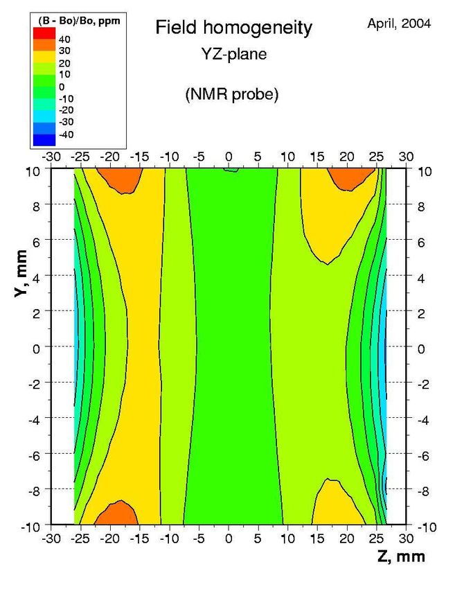
Ch. Bradtke
PhD Thesis, Univ. Bonn, 1999
Equipment List for Frozen Spin Target

Polarizing Magnet: 5 Tesla
Microwaves: 1-2 mW/g @ 140 GHz
Polarizing Refrigerator: Q ≥ 20 mW @ T ≤ 0.5K
NMR: 212 MHz

Holding Magnet: 0.5 Tesla internal solenoid
Holding Refrigerator: Q ≥ 10 mW @ T ≤ 0.05 K
NMR: 21 MHz
Target: Ø15 mm × 50 mm butanol (C4H9OH)
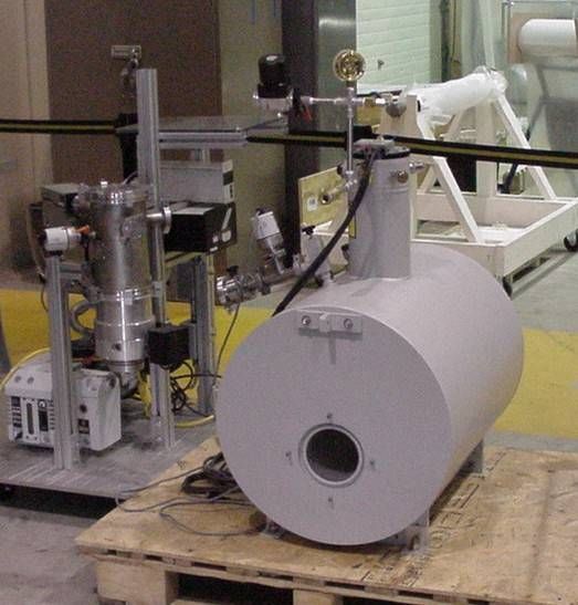
Polarizing Magnet

 Max. Field: 5.1 T
 ∆B/B: < 3×10⁻⁵
 Bore: Ø127 mm

Cryomagnetics, Inc.
Oak Ridge, TN, USA
                      A. Dzyubak, priv. comm..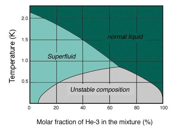
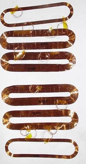
Holding Magnet, Longitudinal
Wire: Ø.1 mm multifilament NbTi, three layers
Dimensions: Ø 50 × 110
Max. Field: 0.42 Tesla
Homogeneity: ∆B/B ~ 3 10-3
Holding Magnet, Transverse (Prototype)
Wire: Ø.1 mm multifilament NbTi, three layers
Dimensions: Ø 40 × 355 mm
Max. Field: 0.27 Tesla
Homogeneity: ∆B/B ~ 5 10-3
Refrigeration Techniques below 1 Kelvin
1. Evaporative cooling of liquid Helium
ṅ = evaporation rate
Q̇T = ṅ L L = Latent heat ≈ constant
∝ L V̇ P V̇ = pump speed ≈ constant
−1/T
P = vapor pressure ∝ e
Vapor Pressure (and therefore cooling power)
decreases exponentiallyRefrigeration Techniques below 1 Kelvin
2. 3He/4He Dilution Refrigeration
Below 0.8 K, a 3He/4He mixture will separate into two phases
Xd Xc
Note: Even at absolute zero, some 3He remains
in the dilute phase (about 6.5%)Thermodynamics of Dilution Refrigeration
At very low temperatures ³He behaves as a non-interacting
gas of spin-½ particles (e.g. electrons in a metal)
2 2/3
Nmk T V 2/3
C = ∝ V T
ℏ 3N
Vc Vc
Since Vd = ≈ Cd ≈ 6 Cc
x 0.065
Experimentally,
C d = 106 T [ J mol−1 K −1 ] C c = 22 T [ J mol−1 K −1 ]
The specific heat of a 3He atom is higher in the lower, dilute
phase than in the upper, concentrated phase!
Therefore, 3He will absorb energy when it dissolves into the dilute phase.
If 3He is removed from the lower part of the mixing chamber, 3He from
the upper part will absorb heat from its surroundings in order to dissolve
into the dilute phase and reestablish equilibrium.
H. London, 1951Cooling Power of Dilution Process
Consider chemical potential m of ³He in the two phases:
= H−TS H = enthalpy
S = entropy
In equilibrium, d =c
H d −TSd = Hc −TSc
Re-arrange,
Hd −H c = T S d −S c “Latent heat of dilution”
T
C C
= T ∫ d − c dT
0 T T
T
= T ∫ 106−22 dT
0
2
= 84 T
“Ideal” cooling power of the dilution process:
Q̇ = ṅ [H d − H c ]
2 2
Cooling power decreases as T-2
= 84 ṅ T Watt /mol KPractical Dilution Refrigeration
3
He is “distilled” from the lower,
dilute phase of the mixing chamber
After distillation, the 3He is recondensed
in a LHe bath at ~1.5K and
returned to the mixing chamber
The cooling power and minimum temperature
depend strongly on heat exchange between
the concentrated (warm) and
dilute (cold) fluid streams
2 2
Q̇T m = ṅ[Hd T m − Hc T c ]
2 2
= ṅ[95T m − 11T c ]
Performance of HX
determines T2cHeat Exchange between 3Hed and 3Hec
3 3
Heat Flow: Hec HX walls Hed
At low temperatures, the main impediment to heat transfer
is the thermal boundary (Kapitza) resistance Rk between the helium
and the HX walls
1 v 31 A 4 4
Only a small fraction of phonons ∝ 10
−5
Q˙ K = [T 2 −T 1 ]
from liquid will enter the HX walls 2 v
3 2RK
2
3
T AT
Or a more familiar form: Q˙K = = T Heat transfer drops fast at low T !
R RkCooling Power with Ideal Heat Exchanger
Cooling power, assuming 100% heat exchange is
determined by molar flow rate and Rk/A of heat exchanger
Q̇T m = ṅ [94.5T 2m−12.5T 2c ]
2 RkT
= ṅ [94.5T m−625 ṅ] (Giorgio Frossati, 1986)
A
Build HX with low RkT OR, large Area
Use sinter of ultra-fine silver or copper powder
to provide several m2 of area40 mesh copper powder
sintered at 870 C
0.08 m2/g
50 m
1 micron silver powder
sintered at 370 C
0.3 m2/g
2 m
150 nm silver powder
sintered at 370 C
1.5 m2/g
2 mOptimization of Heat Exchanger Geometry
To optimize heat exchangers, must consider heat leaks due to both
axial conduction and frictional heating
D2 128L
Qcond =
4L
∫ T dT Qfric =
D
4
ṅV
2
=aD 2 = b D−4
d 2 −4
Minimize Qcon + Qfric : aD bD = 0 Dopt = (2b/a)1/6
dDIntrinsic heat leak as a function of tube diameter HX Length: 1.5 m Flow rate: 1 mmol/s Inlet temperature: 200 mK Outlet temperature: 20 mK
1 micron Ag powder
   Sinter at 250 oC  0.5 m2/g

Outside (dilute):        15 g = 7.5 m2
Inside (concentrated):   8.5 g = 4.2 m2
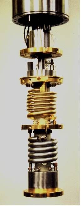
An example of a commercial, vertical dilution refrigerator
© Leiden Cryogenics, BV
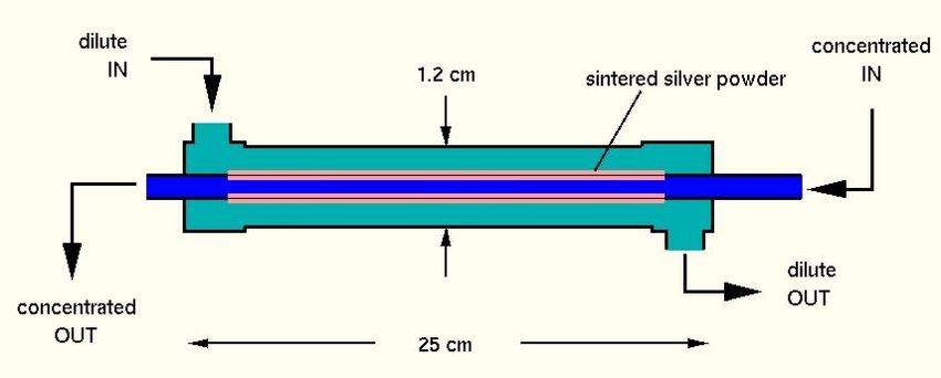
Very nice, but it won't fit inside CLAS...Horizontal Dilution Refrigerator for Frozen Spin Target
T.O. Niinikoski, CERN 1971Hall B Frozen Spin Target
The Frozen Spin Waltz

Step 1: Polarizing

 - Target is fully retracted,
 magnet is lifted to beam height

 - Target is inserted into magnet,
 magnet energized, microwaves on

Step 2: Beam On
  - Microwaves off, magnet off,
  holding coil on

  - Target is fully retracted,
  magnet is lowered

  -Target is fully insert into CLAS
Equipment List for Frozen Spin Target
1 microwave generator + power supply (140 GHz) + misc. waveguide components
    1 power meter
    1 frequency counter
1 RF generator (NMR) + RF voltmeter
2 NMR Q-meters
2 superconducting magnets + 2 power supplies
2 gas panels (4He & 3He/4He)
    29 valves
    13 pressure transducers
    4 flow meters
    2 storage tanks (3He + 4He)

18 vacuum pumps
     6 vacuum transducers
1 Dilution Refrigerator
    18 thermometers
    2 8-channel temperature monitors
    1 AC resistance bridge
    2 superconducting level probes + readouts
    1 capacitance level probe + bridge circuit
    4 micro needle valves + actuators
    2 heaters
Summary - A frozen spin polarized target for tagged photon experiments is under development at Jefferson Lab. - 5 Tesla polarizing magnet is in house. - Superconducting holding coils (~1mm thick), both longitudinal and transverse, are under development. - Horizontal dilution refrigerator is under construction. - Positioning system for Hall B is still in conceptual design stage.
You can also read