Hot runner control technology Devices with system character
←
→
Page content transcription
If your browser does not render page correctly, please read the page content below
Hot runner control technology
Devices with system character
• A unified concept for all device sizes
• Superior for all hot runner systems
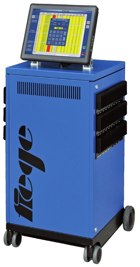
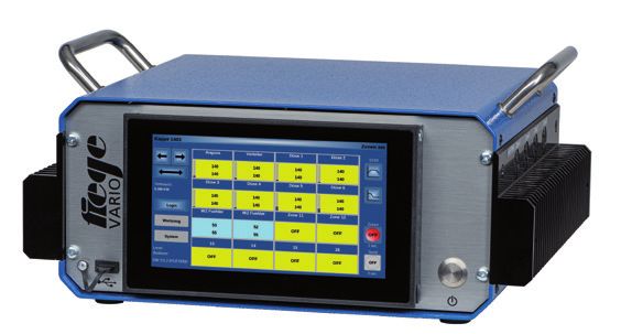
VARIO JETmaster TP
Tabletop device for 4 to 32 zones in steps of Standalone device for 24 to 240 zones in
4 Control via microcontroller with tiltable 7“ steps of 8
multi touch panel Control via industrial PC with 15“ touch panel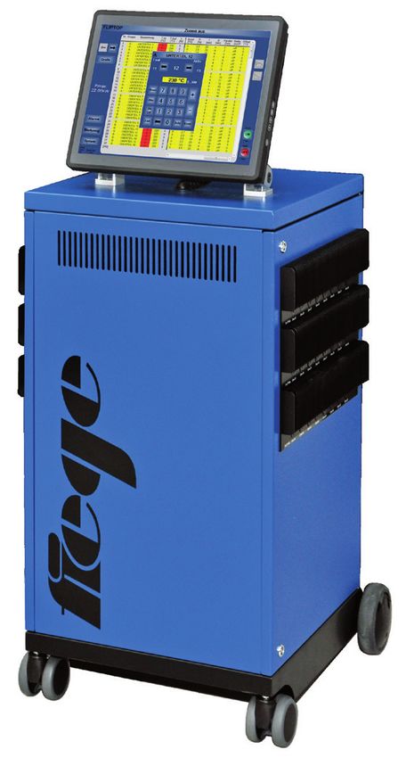
User interface Device rear view
1 1 5 1. Customized mould connection
1. Tiltable 7“ multi touch panel 2. Customized power supply
4 4
2. USB connection 3. Ethernet connection
3. Power button 1 3 4. Alarm contact
2 3 2
4. Fuses 5. ext. reduction and boost
Depending on specification, the rear view may differ from this picture.
User interface Device rear view
1
1
2 6
2
3
1. USB- and Ethernet connection
4 5
2. Customized mould connection
3. Customized power switch
1. Industrial PC with 15” 4. ext. reduction and boost
touch panel 5. Alarm contact
2. Fuses 6. Power switch
Depending on specification, the rear view may differ from this picture.
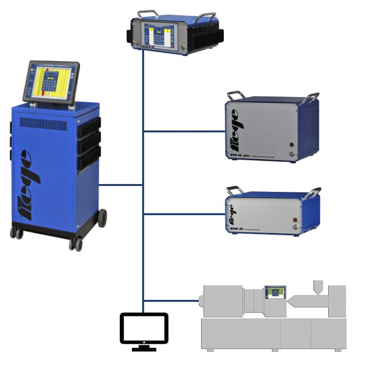
Kombinationsvarianten
All device data and tool settings can be centrally stored and managed via the
ethernet connection.
NVS
The ethernet connection will continue to be used to connect additional Needle Valve Control
devices, such as needle valve control NVS* and cavity pressure measurement
DMS*, to the devices. These then perform the operation and visualisation.
DMS
Ethernet Cavity Pressure Measu-
Various injection moulding machines can be connected via conventional data rement
interfaces or via the ethernet so that operation and visualisation occurs on
the machine‘s screen.
*See separate data sheet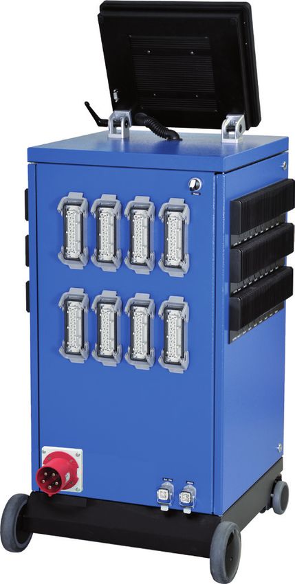
Technical Data
Housing:                                              Heating outputs:                                         JETmaster TP: CEE 32A, CEE 63A, CEE 125A,
Aluminum, colour RAL 5010 gentian blue, special       230 VAC/16 A =3680 W per zone, trouble-free              Multiple feed, connector
colours available upon request                        switching algorithm, secured by super-fast-acting
                                                      (FF) safety fuses 16 A, 6.3 x 32 mm                      Interfaces:
Dimension/weight:                                                                                              1xUSB-external, 1xEthernet, OPC/UA, optional:
According to table of “equipment designs”             Alarm output:                                            RS232, RS485, TTY
                                                      Potential-free alarm contact, max. load up to 250
Temperature control:                                  VAC / 2A (can be inverted)                               Control fuse:
Microprocessor controlled multi-loop controller                                                                VARIO: 2 A 250V slow (miniature fuse radially
with automatic computation of the control para-       Safety shutdown:                                         wired round)
meters for each zone                                  Load shedding in the case of broken-down Triac           JETmaster TP: Fusible cut-out MT 6.3 A, 5 x 20 mm
                                                      (short circuit)
Operation/ Visualisation:                                                                                      Ambient temperature:
VARIO: Microcontroller with tiltable 7“ multi touch   Reduction / Boost:                                       Operation 0...+50°C, storage -30...+70°C
panel                                                 Can be switched both manually and externally
JETmaster TP: Industrial PC with 15” touch panel      via the 24 VDC control circuit.                          Climatic application class:
                                                                                                               According to DIN 40 040, relative air humidity ≤
Sensor input:                                         Mould connection:                                        75% annual average, non condensing
Thermocouple Fe/CuNi, switchable to Ni/CrNi with      According to customer specification
internal thermocouple reference junction                                                                       Protective system:
                                                      Power supply:                                            IP20
Temperature range:                                    400 VAC +10...-10%, 50...60 Hz, 3P / N / PE,
0 - 500°C, can be converted to 32 - 932°F             other voltages upon request                              Protection class:
                                                                                                               I
Calibration accuracy:                                 Power supply:
≤ 0,25 %                                              VARIO: CEE 16A, CEE 32A, 4m

                                                                                                                                   Device models

   Type                              Zones                         Type-no.                          Size(mm)                        Weight app.
                                                                                                     BxHxT                           (kg)

   VARIO 4 TP                        4                             2410-xxxx-04                      341 x 175 x 250                 6

   VARIO 8 TP                        8                             2410-xxxx-08                      341 x 175 x 250                 7

   VARIO 12 TP                       12                            2410-xxxx-12                      341 x 260 x 250                 9

   VARIO 16 TP                       16                            2410-xxxx-16                      341 x 260 x 250                 10

   VARIO 20 TP                       20                            2410-xxxx-20                      341 x 345 x 250                 12

   VARIO 24 TP                       24                            2410-xxxx-24                      341 x 345 x 250                 13

   VARIO 28 TP                       28                            2410-xxxx-28                      341 x 430 x 250                 15

   VARIO 32 TP                       32                            2410-xxxx-32                      341 x 430 x 250                 16

   JETmaster TP                      24 to 96                      1610-xxxx-96*                     480 x 1360 x 470

   JETmaster TP                      104 to 144                    1610-xxxx-144*                    480 x 1590 x 470

   JETmaster TP                      152 to 192                    1610-xxxx-192*                    480 x 1800 x 470

   JETmaster TP                      200 to 240                    1610-xxxx-240*                    special

*corresponds to the number of zones                                                                                                       Options

xxxx: will be replaced by a customized version number when the order                  Serial interfaces                       Type-no.
 is placed.
                                                                                      RS485                                   xxx1-xxxx-xx

                                                                                      RS232                                   xxx2-xxxx-xx

                                                                                      TTY                                     xxx3-xxxx-xx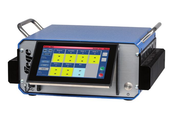
Functions

  •M
    icro-process controller with PID algorithm and automatic adaptation          • P otential-free alarm contact configurable as opener or closer

  • Each zone 230V / 16 A, 3680W                                                  • S afety switch-off in the case of broken-down Triac

  •A
    ccess levels for operators, setters and administrators                       •M
                                                                                    ould data memory for more than 500 moulds

  • F unctional in any desired language                                          •M
                                                                                    ould data can be transferred to all devices of the TP- and VARIO-
                                                                                   series. Therefore, the moulds are operational without restart.
  •A
    utomatic starting control for drying of moist heaters
                                                                                  • T emperature recorder for all active zones with export function
  • T emperature monitoring
                                                                                  •A
                                                                                    utomatic tool inspection and diagnostic function with logging
  •D
    isplay of sensor breakage and polarity reversal                               (analyze wiring)

  •A
    utomatic and manual switching to manual mode in case of sensor               •V
                                                                                    ARIO: Connection of two devices up to a total of max 32 zones.
   error                                                                           Operation is via a device.

  •A
    ny number of zones can be switched in parallel and controlled by the         • F urther external devices, e. g. needle valve control and cavity pressure
   pilot zone                                                                       measurement, connectable via ethernet which are operated, visualised
                                                                                    and managed via the devices of the TP- and VARIO- series
  • T emperature reduction can be controlled manually and by the injection
    moulding machine, with or without reduction delay                             • J ETmaster TP: up to 8 photos can be added and labelled per mould

  •D
    evice shutdown timer in case of timeout of an external reduction             • J ETmaster TP: optionally available with offset screen
   (adjustable)
                                                                                  • P C-Software for administration, evaluation, documentation and
  •B
    oost function can be controlled manually and externally by the                 archiving of mould data
   injection moulding machine using safety timer
                                                                                  • P rocess documentation via log book function on USB or internal
  • S tart timer for stored tool data set via integrated timer                     storage

  • P ower-[A] or output display of the individual heaters, already with         • S creenshot function for the screen content displayed directly as an
    switched off zones                                                              image file on USB

  •D
    isplay of the mould connection power, already with switched off              • Interfaces: 1 external USB, 1 Ethernet, additional interfaces optionally
   zones                                                                            for control by the machine screen of the injection moulding machine

  •H
    eating monitoring                                                            • E xtremely compact, uniform, simple and logical operation

  • P ower consumption display                                                   • F anless and maintenance-free

  • P ower reduction in the event of overload of the mains connection            •V
                                                                                    ARIO: easy transport through practical carry handles; devices
                                                                                   stackable
  • S ynchronisation function for uniform heating of all zones
                                                                                  •C
                                                                                    ustomized mould connection and mains connection without extra
  •G
    roup management for multiple, stack and multi-component moulds                charge

  •H
    eatup order in groups                                                        • If required, Triacs are exchangeable in a few simple steps

  • E arly detection of leakage in the mould                                     • Fuses accessible from outside

  •C
    hange over from control zone to monitoring zone with limit value             • F ree software updates
   monitoring

                     AGE
           ´ L L MAN U
        WE       FOR
                     YO
         THAT                      Phone: +49 6201 259 58-19                             Do you have any questions about our products?
                                   sales@fiege-electronic.com                                       Our service advisors will be happy to help.
                                                                                                                                                                 35/2021

Fiege electronic GmbH               Im Technologiepark 5/1             D-69469 Weinheim
Tel.: +49 6201 259 58-0             info@fiege-electronic.com          www.fiege-electronic.com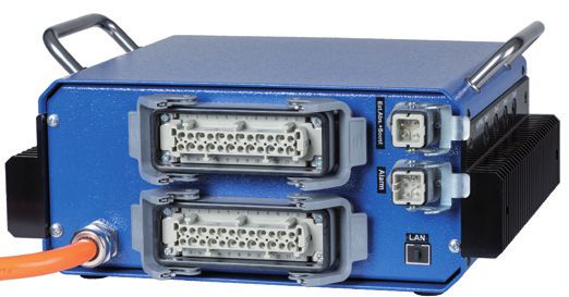
You can also read