Fuel efficiency driver assistance system for manufacturer independent solutions
←
→
Page content transcription
If your browser does not render page correctly, please read the page content below
Fuel efficiency driver assistance system for manufacturer independent
                                  solutions
                                                 Tianyi Guan1 and Christian W. Frey2

   Abstract— Energy efficiency has become a major issue in                 partial power train model, which at the same time takes
modern trade, business and environmental perception. While                 more vehicle specific characteristics into account than e.g.
the next generation of zero emission propulsion systems are                smartphone app approaches. The computations are done in
still under development, it is already possible to increase fuel
efficiency in regular vehicles by applying a more fuel efficient           the on-board EXPERT components within every individual
driving behaviour. This particularly holds true for transport              vehicle. The adaptive model is then used in an optimization
companies, where even small percentage savings can accumulate              routine that can generate fuel efficient guidelines depending
to huge absolute savings. Although there are common fuel                   on the current vehicle and the current state. Because no
efficiency guidelines, they are often imprecise and not adapted            height maps, slope information, object detection, traffic light
to a specific vehicle. Furthermore drivers may not even know
the fuel efficiency rules or lack the motivation to apply them             information, speed limit information or route information is
in practice. In this paper, an online driving assistance system            available, the system identification and the fuel efficiency
is presented that assist drivers during their journeys by giving           guideline generation is solely based on CAN-Bus data. Fuel
them fuel efficiency guidelines that are suited for the current            efficient route selection is not the topic of this paper, but
situation and vehicle. The driver assistance system uses an                rather the assistance of the driver during actual driving.
internal manufacturer independent model that can adapt to
the current vehicle solely based on online CAN-Bus data.                                     II. EXPERT SYSTEM
                      I. INTRODUCTION                                         The EXPERT system is primarily designed for freight
   Several authors have published solutions in the area of                 forwarding companies, which want to keep track of their
fuel efficient driving. The approaches range from complete                 fleet and increase the fuel efficiency of their drivers. An
vehicle control to passive driver assistance systems. Active               overview of the system is given in figure 1. From the
approaches include the works of [1] [2] [3]. They are usually              figure the reader can see that EXPERT is a collaboration of
manufacturer specific due to the necessity of solid knowledge              different components. The ”EXPERT Information System” is
about the vehicle. Topology height maps and exterior sensors               a fleet management system, which resides at the management
(e.g. radar and camera systems) are used to allow model                    headquarters and communicates with vehicles within the
predictive approaches. In contrast to active approaches, pas-              fleet via the ”Green Box”. The ”Green Box” is the main
sive driver assistance systems only send audiovisual or other              communication hub of every EXPERT assisted vehicle that
information to the driver so that he or she can follow the                 enables the communication of all other EXPERT hardware
proposed guideline to his or her best ability [4]. They do not             components. It is installed into every vehicle’s cabin. One
necessarily rely on complete vehicle models and only con-                  of its most important tasks is to relay the current CAN-
centrate on the present situation. More rudimentary passive                Bus information to other systems. CAN-Bus information in
systems can be found among smartphone apps which only                      trucks is specified according to SAE J1939 [7]. But since
warn the driver of excessive acceleration and braking [5] [6]              manufacturers sometimes do not exactly comply with all
based on basic device internal sensors. The driver assistance              specification standards, only a limited amount of CAN-Bus
system proposed in this paper is a passive system. It is an                information can be used in EXPERT that can be expected
integral part of a larger fleet management assistance system               to be valid for most vehicles. The CAN-Bus data used in
called EXPERT (EXPert System for a more Efficient Road                     EXPERT consists of vehicle velocity, fuel consumption rate,
Transportation). The system is primarily designed for freight              gear level, brake switch, clutch switch, engine speed, engine
forwarding companies which want to improve the fuel and                    torque, acceleration pedal position, vehicle ID and driver
cost efficiency of their fleet. The functionality ranges from              ID. The different CAN-Bus messages have different update
fleet management support to individual driver assistance. The              rates which range from 5 Hz (e.g. gear level) to 100 Hz
latter will be the main focus of this paper. Different to                  (e.g. engine speed) and are synchronized according to the
model dependent and therefore often manufacturer specific                  update rate of the assistance system (e.g. 1 Hz). Apart from
approaches, EXPERT will be applicable to a great variety                   the ”Green Box”, a HMI device (e.g. a tablet computer)
of vehicles due to an internal online multivariable adaptive               is assigned to every driver of the fleet. It can be fixed to
                                                                           the dashboard of each vehicle. The HMI device contains
  1 T. Guan is with Fraunhofer IOSB, Karlsruhe, Baden-Württemberg 76131
                                                                           the ”Driving Efficiency Module” software developed by
Germany tianyi.guan at iosb.fraunhofer.de                                  Fraunhofer IOSB, which will be the main focus of this paper.
  2 C.W.   Frey is with Fraunhofer IOSB, Karlsruhe, Baden-
Württemberg        76131       Germany       christian.frey at            The ”Driving Efficiency Module” (see figure 1) consists of
iosb.fraunhofer.de                                                         an adaptive model and an optimization sub-module, which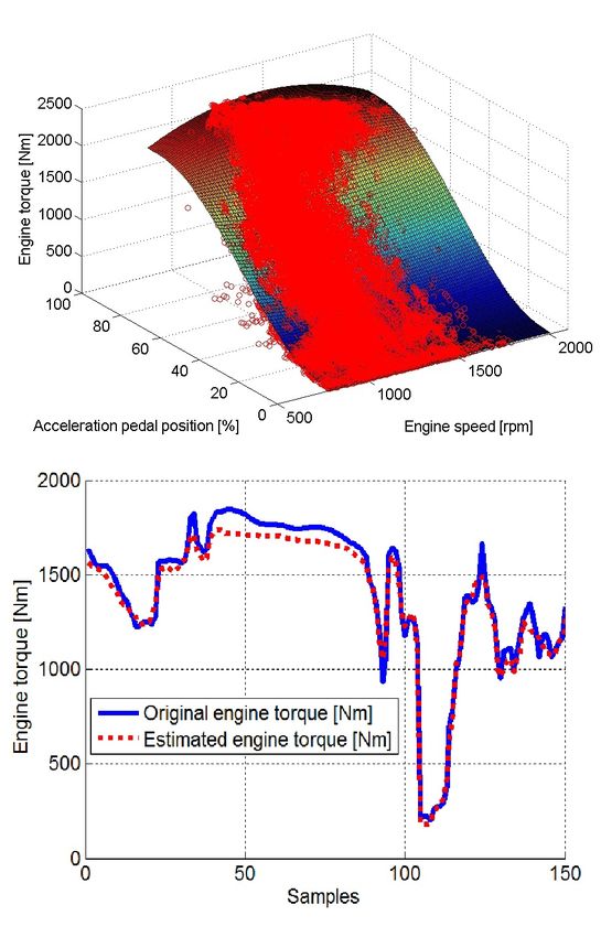
generates fuel efficient driving guidelines for the driver.       horizons are generally infeasible.
These guidelines are relayed to the ”Co-Pilot”, which will         The transmission model is described by the static transmis-
display the information on the HMI device through numbers,
colors and acoustic hints. During operation, the driver retains
full control of the vehicle at all times. When the delivery
is executed, the driver can unplug the HMI device and
start with a new assignment in a different vehicle. There

                                                                  Fig. 2. Partial power train formulation with most important input and
                                                                  output signals after model adaptation

                                                                  sion ratio it (G) depending on the selected gear level G. It en-
                                                                  ables the estimation of the engine speed ωe depending on the
                                                                  vehicle velocity v and vice versa. Internal inertia and clutch
                                                                  dynamics are neglected. Thus, measurement samples during
                                                                  gear shifts and open clutches are not used for estimation.
                                                                  The transmission ratio is the ratio of the input transmission
                                                                  rotation speed ωt,in and the output transmission rotation
                                                                  speed ωt,out . Note that ωt,in is assumed to be equivalent to
                Fig. 1.   EXPERT system overview
                                                                  the engine speed. The transmission ratio estimation is given
                                                                  in (1).
are currently several technical and economic constraints                                       ωt,in      ωe
imposed on the EXPERT system. First of all, routes and                               it (G) =        =                         (1)
                                                                                              ωt,out    ωt,out
position dependent velocity limits cannot always be provided
by fleet headquarters. Furthermore, it can generally not be       ωt,out is calculated from the current vehicle speed v and
expected that the vehicles using EXPERT possess advanced          divided by the wheel radius rw . If the wheel radius is
object detection sensors like radar or camera systems. This       unknown, it can be set to any positive non-zero value because
makes velocity dependent guidelines difficult to implement        the relation between vehicle speed and engine speed will still
in practice. Precise height maps are usually subject to fees      remain the same.
[8] and free of charge height maps have a low resolution                                  v = ωt,out rw                     (2)
[9]. Therefore model predictive strategies [1] [2] are also
infeasible. The strategies used in the ”Driving Efficiency        The online calculated raw ratios are collected for each
Module” instead will be explained in the upcoming sections.       observed gear level category and saved in a corresponding
                                                                  ring buffer. In each category, the distribution of the ratios
  III. ADAPTIVE PARTIAL POWER TRAIN MODEL                         is estimated. If the standard deviation decreases below a
   Due to the complex interaction of internal and external        certain threshold (design parameter), the raw ratio collection
propelling and resistant forces in the different vehicle com-     for the gear level is deemed as trustworthy. The ratio of this
ponents, it is necessary to simplify the vehicle to obtain a      gear level category is then estimated as the median of the
unified model with a small amount of unknown parameters           hitherto saved data. The estimation is updated every second.
that can be adapted online and used for a great variety           If the internal ring buffers are full, the new estimation
of different vehicles. For the purpose of EXPERT, the             update is set to the average of the current estimation and
proposed power train model (see figure 2) is a static partial     the previous estimation. Finally, a decreasing exponential
model of the vehicle’s power train, which puts its focus          function is fitted through the trustworthy medians to retrieve
on the current situation. It only contains an engine and          estimates for all gear levels.
a transmission model that additionally draws information          The engine model is described by an engine torque map
from vehicle speed. In case of a vehicle with automatic           and a fuel consumption rate map. The fuel consumption
transmission, only the engine is modelled. Vehicle internal       rate map is defined as a polynomial of low degree (e.g.
slip and vehicle internal friction of any kind are neglected,     first to third degree). It depends on engine torque Te
because necessary measurements to estimate internal inertia       and engine speed ωe [10]. The equation is stated in (3).
and friction of the various components are not available.         The polynomial coefficients are estimated using equality
External resistance forces are also neglected. The reason         constrained least squares. The equality constraints enforce
for this type of partial model formulation is that due to the     the expectation that if the engine speed is zero, the fuel
previously stated system constraints, the ”Driving Efficiency     consumption rate is also zero. The estimation primarily
                                                                                                      dVf uel
Module” will not suggest precise velocity or acceleration         requires fuel consumption rate        dt , engine speed ωe
pedal values to the driver or anticipate his or her behaviour     and engine torque information Te from the CAN-Bus.
(see section IV for further details). With the given con-         Additionally, status information about clutch and gear level
straints, model predictive approaches or long integration         G are needed, because measurements during the transient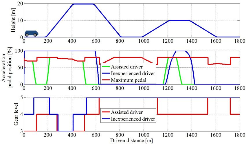
gear shift process are not regarded. beginning of every new journey. By calculating the average
of the historic parameter estimates and the current estimates,
dVf uel the model adaptation is able to improve over time.
= a0 + a1 Te + a2 ωe + ... + aM TeN ωeN (3)
dt
The engine torque map is dependent on the acceleration pedal IV. O PTIMIZATION AND FUEL EFFICIENCY GUIDELINE
position u and engine speed ωe [11]. It is initially described GENERATION
by a polynomial of low order if only sparse CAN-Bus data is
The fuel efficiency guidelines for the driver are calculated
available. This case typically arises if the ”Driving Efficiency
from the partial power train model and the current CAN-
Module” is confronted with a new vehicle. As large data
Bus data. The optimization uses cost function minimization,
sets become available, e.g. collected over several hours, the
which penalizes unfavourable driving behaviour. In this
characteristic map changes to a three segment spline S(u, ωe )
paper, an unfavourable driving behaviour is regarded as a
approximation. The segments are divided at certain acceler-
driving behaviour that leads to overall high fuel consumption
ation pedal values, where significant changes in appearance
and high attrition to the vehicle. Naturally, not driving at
are expected (e.g. at u = 20% and u = 80%). Thus, the
all is the best way to accomplish both goals. But at the
spline segments can use different types of polynomials to
same time, excessive deviation from the driver’s wishes is
account for local engine torque map characteristics. The
also unwanted, which includes long trip duration. All these
spline estimation is partitioned into three steps. Before the
aspects can be highly contradictory to each other. Thus, the
estimation can begin, a histogram test is performed to discard
goal is to find an optimal trade-off. Due to the previously
outliers. After the histogram test, a parabola shaped full load
stated system constraints, the ”Driving Efficiency Module”
curve is estimated using engine torque and engine speed
does not propose a precise set velocity to the driver, but a
data for which u > 80%. From the full load curve’s only
maximum tolerable acceleration pedal position (comparable
maximum, the torque maximizing engine speed ωe,m can be
to the approach in [4]) that should not be exceeded and
retrieved. Finally, the spline coefficients are estimated using
two specific gear levels in case of a manual transmission.
equality constrained least squares that takes the common
The maximum tolerable pedal position umax,opt is a trade-
spline intersection equality constraints into account [12]. The
off between torque maximization and fuel consumption rate.
different polynomials are developed at different operation
In most cases, pressing down the acceleration pedal will
points: ωe,m , uh = 100% and um = 50%. All these methods
generate a higher torque and higher vehicle acceleration, but
support the reliability of the engine torque map and allow a
will also lead to a higher fuel consumption rate (see figures
robust interpolation and extrapolation behaviour within the
4 and 5 in section V). The inexpediency of a pedal position
observed data scope. The three polynomials of the spline are
choice is described by the cost function (8) for the current
given in equations (4) to (6). The spline is stated in (7). The
discrete time-stamp t.
estimation requires acceleration pedal position, engine speed
and engine torque information from the CAN-Bus. Cu (t) = Cf uel (t) + Ctorque (t) + Csmooth,G (t, t − 1) (8)
2
P1 (u, ωe ) = b0 u (4) The first cost term Cf uel (t) penalizes the fuel consumption
P2 (u, ωe ) =c0 + c1 (u − um )+ rate. Depending on the current engine speed ωe (t) and a pos-
sible pedal candidate uc , an engine torque candidate Tec =
c2 (ωe − ωe,m ) + ...+ (5)
Te (uc , ωe (t)) is computed using the estimated torque map
c15 (u − um )3 (ωe − ωe,m )3 (7). The torque candidate and the current engine speed will
dV (T ,ω (t))
P3 (u, ωe ) =d0 + d1 (u − uh )4 + lead to a fuel consumption rate candidate f uel dtec e
calculated from the estimated fuel consumption rate map (3).
d2 (ωe − ωe,m )2 + (6) At the same time, a second cost term Ctorque (t) encourages
4 2
d3 (u − uh ) (ωe − ωe,m ) engine torque maximization to allow necessary vehicle ac-
celeration. Because the two cost terms cannot be directly
P1 (u, ωe ), u < 20%
compared to each other, normalization values need to be
Te = S(u, ωe ) = P2 (u, ωe ), 20% ≤ u ≤ 80% (7)
introduced. The fuel consumption rate is normalized by a
P3 (u, ωe ), u > 80%
high fuel consumption rate value dVdt max
. Naturally, it can
The estimation of the engine model is deemed as trustworthy be defined as the maximum value ever encountered in the
when the internal ring buffers are filled. In the current system collected CAN-Bus data. But in order to avoid excessive
the buffers are set to a capacity of 30 minutes of valid data. measurement errors or high values that rarely occur, it is
The estimation is updated every second. If the ring buffers beneficial to define the normalization as the sum of the
are full, the new estimation update is set to the average of expectation and the standard deviation of the collected fuel
the current estimation and the previous estimation. The pa- consumption rate data set. The normalization of the engine
rameters of the partial power train model components change torque Te,max can defined in the same way. Finally a third
little over time. Thus, it is beneficial to save the estimation cost term Csmooth,u is added to the two previous cost terms.
parameters for future journeys. Otherwise, the system has It serves as a regularization term that penalizes oscillations
to wait for the completion of the vehicle adaptation at the in the optimization result with the weighting λu as a design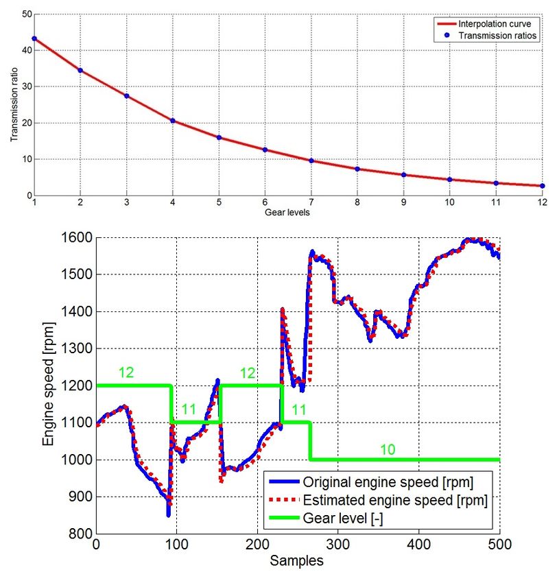
parameter. The cost terms are stated in (9) to (11).              engine speed ωe,cut or higher than the estimated maximum
                            dVf uel (Tec , ωe (t))                engine speed ωe,max .
               Cf uel (t) =                                 (9)
                                  dVmax                                             Gopt (t) = arg min CG (t)                  (16)
                                                                                                    Gc ∈G
                                    Te,max
                 Ctorque (t) =                            (10)    The second gear proposal Gbrake favours the lowest feasible
                               Te (uc , ωe (t))
                                                                  gear level.
    Csmooth,u (t, t − 1) = λu |uc − umax,opt (t − 1)|     (11)
                                                                   Gbrake (t) = arg min |Gc − min{G }| + CdG (t, t − 1) (17)
The maximum tolerable pedal position umax,opt (t) is the                              Gc ∈G
acceleration pedal position candidate uc of all feasible pedal    Because the optimization depends on the current accelera-
positions U = {u|0% ≤ u ≤ 100%} that minimizes (8).               tion pedal position, short-time transient processes (e.g. gear
               umax,opt (t) = arg min Cu (t)              (12)    shifts) must be additionally detected. In these scenarios the
                                    uc ∈U                         previous results are maintained. Apart from the previously
In case of a manual transmission, two specific gear levels        discussed primary guidelines, the driver will be additionally
are proposed to the driver in addition to umax,opt (t). The       notified to switch off the engine during idling phases and
first gear level proposal Gopt (t) is a trade-off between fuel    to coast instead of braking if the brake pedal is pressed.
consumption and torque maximization, designed for regular         In autonomously controlled systems [1] [2], different op-
driving and acceleration. The second gear level proposal          timization variables can be jointly calculated and applied.
Gbrake (t) maximizes the braking torque of the engine and         In the case of EXPERT, it is uncertain if the driver will
is only needed if the driver wants to reduce speed through        apply both guidelines at the same time and it is always
coasting. It is assumed that the driver can distinguish between   uncertain which pedal position will be chosen because only
the two cases. The calculation of Gopt (t) is conducted in two    a maximum pedal position is suggested. Thus, the pedal
steps. In the first step, two other gear candidates Geco (t)      optimization and the gear choice optimization are separately
and Gtorque (t) are calculated. Geco (t) is a gear level that     performed depending on the current input measurements of
favours low fuel consumption, suitable for coasting or low        the respective cost functions. The optimization problem can
torque demand situations, e.g. maintaining speed on flat          be solved with a direct discrete search in real time on a tablet
terrain. In this case the gear should be chosen as high           computer device. Although direct searches or enumerations
as possible. Gtorque (t) is a gear level that favours torque      are usually inefficient, consider that if the pedal discretization
maximization, suitable during acceleration and hill climbing.     is set to 1% and the manual transmission has 6 gears,
The corresponding engine speed can be calculated from the         the model is only executed 106 times during optimization.
torque map (7) and the current pedal position. In a second        Furthermore, direct searches have the benefit of finding the
step, a cost function CGG (t) is defined as the weighted          global minimum of the cost function if discretization is
average of Geco (t) and Gtorque (t). The weighting is simply      sufficiently subtle. The fuel efficiency guidelines and the
the current acceleration pedal position u(t) ranging from 0       model adaptation can be updated with a maximum frequency
to 1. It is assumed that u(t) is consistent with the driver’s     of at least 1 Hz. It is assumed that higher update rates will
torque demand. A low pedal position will favour Geco (t)          overwhelm the driver. The regularization terms assure that
while a high pedal position will favour Gtorque (t).              the generated guidelines will not excessively fluctuate, so
                                                                  that the driver does not need to constantly check the HMI.
           CGG (t) =(1 − u(t))|Gc − Geco (t)|+                    It is noted here that there are other characteristic maps that
                                                          (13)
                       u(t)|Gc − Gtorque (t)|                     can be used to generate fuel efficiency guidelines, e.g. the
Finally, a temporal regularization term CdG (t, t−1) is added     specific fuel consumption or efficiency maps. The estimation
to avoid possible oscillations in the optimal solution. tshif t   of these maps has turned out to be challenging on the
is the time stamp of the previous change in the Gopt solution.    available test data taken from a real world test drive because
λG is a weighting value that describes the length of the time     the automatic transmission of the test vehicle mostly stayed
period, in which a change in Gopt is regarded as early (e.g.      within a confined operation area. This is also the main reason
2 seconds).                                                       why neural networks approaches were not used for model
                                                                  adaptation.
    CG (t) =CGG (t)+

                             0, Gc = Gopt (t − 1)         (14)                                V. R ESULTS
                CdG (t, t − 1), otherwise                            In this chapter the authors present results based on real
                                                                  world CAN-Bus data and simulated environment. The avail-
                                        λG
                CdG (t, t − 1) =                          (15)    able CAN-Bus data are records of a truck delivery that
                                    |t − tshif t |                stretches over six hours. This data is used to evaluate the
The minimization of CG (t) with respect to all gear level         performance of model adaptation. The transmission ratio
candidates Gc within the feasible set G yields the optimal        estimation result is shown in figure 3 (top). It has as many
gear Gopt (t). G only contains gear levels that do not lead to    as 12 gear levels because the transmission is an automatic
an engine speed that is lower than the estimated fuel cut-off     transmission. A red interpolation curve shows the smooth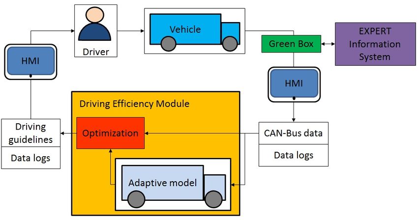
and gradual decline of the ratio levels. Using the estimated
gear ratios, the engine speed can be predicted depending on
the vehicle speed and selected gear. The result on a random
sequence is displayed in figure 3 (bottom), which shows that
the estimated engine speed can mostly follow the engine
speed measurement with slightly stronger deviations during
gear shifts, because the transmission model is static.
The estimation result of the engine torque map is displayed
Fig. 4. Estimated engine torque (best viewed in color): Estimated engine
torque map (Top), Estimated engine torque compared with CAN-Bus data
(Bottom)
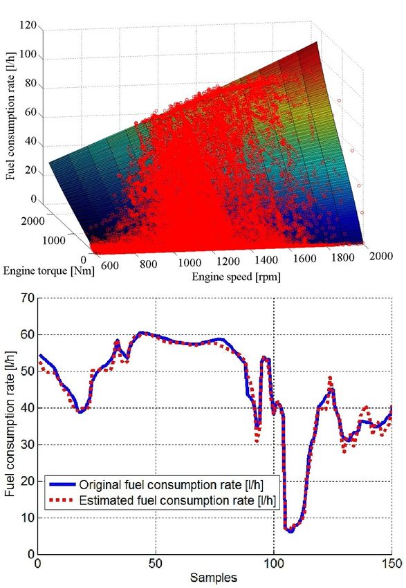
The estimated fuel consumption rate qualitatively follows the
fuel consumption rate measurement. Deviations of more than
Fig. 3. Transmission ratio estimation (best viewed in color): Estimated
10% can occur because the fuel consumption rate map is a
transmission ratios (top), Estimated engine speed (bottom) static polynomial of third degree.
The effect of the application of the fuel efficiency guide-
in figure 4 (top). The measurement points which remain lines has been evaluated within a Matlab/Simulink simulated
after the histogram outlier test are illustrated as red circles. environment. An example scenario is shown in figure 6. The
Note that the engine torque provided by the CAN-Bus is the simulated vehicle has a mass of 4000kg and 5 gear levels.
torque developed in the cylinders according to SAE J1939 The road topology has a length of 1800m with two hills.
specification [7]. It is therefore never negative. The three The desired travelling speed is 80 km h . The simulated inex-
segment spline is fitted to the measurement points and shows perienced driver is simulated by a PI controller, who shifts
stable interpolation and extrapolation behaviour. The spline gears heuristically depending on certain velocity thresholds
equality constraints have been imposed on eight different (e.g. 10 km km km km
h , 30 h , 50 h , 70 h ). In this example, it is
support points along the acceleration pedal positions of 20% apparent that the driver or PI controller makes full use of
and 80%. Several outliers from the original measurement the maximum control range (acceleration pedal) and tends
collection could not be discarded. But compared to the to remain at a high gear, which sometimes leads to long
main measurement point concentration they are only few acceleration phases (0m to 600m). The EXPERT assisted
in numbers. Using the estimated torque map, the engine driver does not completely press down the acceleration pedal
torque can be estimated. An example is given in figure 4 and sometimes shifts to a lower gear if acceleration is
(bottom). The estimated engine torque qualitatively follows demanded (e.g. 0m to 100m) or if the engine speed is too
the recorded engine torque signal, but deviations of more low (e.g. 1700m to 1800m). In this specific scenario, fuel
than 10% can occur because the engine map is static and is savings of up to 11% could be achieved by the EXPERT
composed of polynomials of low degree in order to avoid assisted driver compared to the inexperienced driver, who
instabilities. shifts heuristically according to the current vehicle speed.
The estimation result of the fuel consumption rate map is Furthermore, the EXPERT assisted driver had a 2% shorter
displayed in figure 5 (top). The original measurement points trip time. Note that in this specific experiment, the inexpe-
are illustrated as red circles. A polynomial of third degree rienced driver actually shifts up earlier than the EXPERT
is fitted to the measurement points. It shows stable inter- assisted driver. The commonly known fuel saving guideline
polation and extrapolation behaviour. Using the estimated of ”shifting up early” actually does not apply to all cases.
fuel consumption rate map, the fuel consumption rate can Indeed, engines usually have their highest efficiency at mid-
be estimated. An example is given in figure 5 (bottom). range engine speeds and high torque [10]. Thus, shifting to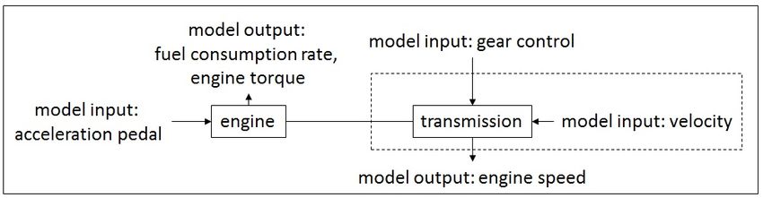
train, namely the engine and the transmission. The fuel
                                                                              efficiency guidelines primarily consist of a currently sensible
                                                                              maximum acceleration pedal position that should not be
                                                                              exceeded and two gear level proposals in case of a vehicle
                                                                              with manual transmission. The guidelines are obtained from
                                                                              the minimization of a pair of cost functions based on the
                                                                              model and the current CAN-Bus data. This optimization
                                                                              strategy only requires CAN-Bus data and no knowledge of
                                                                              the environment or object detection. Simulations have shown
                                                                              that significant fuel savings can be achieved compared to a
                                                                              driver with little experience in fuel efficiency driving. Future
                                                                              works include the improvement of the simulation framework.
                                                                              The driver simulation will be improved to emulate a more
                                                                              experienced driver. A driving simulator is also currently
                                                                              under construction. With additional CAN-Bus data records
                                                                              from different drivers and vehicles, it may be possible to
                                                                              estimate other types of characteristic maps (e.g. efficiency
                                                                              maps) that lead to a simpler and more precise optimization.
                                                                              Although a complete dynamic vehicle model is currently not
                                                                              used in EXPERT due to system constraints, the estimation
                                                                              of additional unknown vehicle and environment parameters
Fig. 5. Estimated fuel rate (best viewed in color): Estimated fuel rate map   (e.g. vehicle mass) is of great scientific interest. Should ad-
(Top), Estimated fuel rate compared with CAN-Bus data (Bottom)
                                                                              vanced information about the environment become available
                                                                              in the future, a model predictive approach would become
                                                                              feasible and the formulation of an adaptive dynamic vehicle
a mid-range engine speed during acceleration can actually
                                                                              model would be of great assistance. The ”Driving Efficiency
be more efficient than shifting to a low engine speed. Also
                                                                              Module” has been implemented in an Java/Android envi-
note that the fuel savings naturally depend on comparison of
                                                                              ronment and will be installed into several test vehicles.
scenarios and drivers and may vary from case to case.
                                                                              Upcoming field tests incorporating 30 different trucks and
                                                                              different drivers will be conducted over several months to
                                                                              evaluate the performance of EXPERT.
                                                                                                          R EFERENCES
                                                                               [1] L. Nielsen A. Fröberg, E. Hellström. A real time fuel optimal cruise
                                                                                   controller for heavy trucks using road topography information. SAE
                                                                                   Technical Paper Series 2006-01-0008, 2006.
                                                                               [2] V. Krebs S. Terwen, M. Black. Predictive powertrain control for heavy
                                                                                   duty trucks. 1st IFAC Symposium on Advances in Automotive Control,
                                                                                   pages 121–126, 2004.
                                                                               [3] S. Schnick X. Li W. Huang, D. Bevly. Using 3d road geometry
                                                                                   to optimize heavy truck fuel efficiency. Proceedings of the 11th
                                                                                   International IEEE Conference on Intelligent Transportation Systems,
                                                                                   2008.
                                                                               [4] F.U. Syed D. Filev. Applied intelligent systems: blending fuzzy logic
                                                                                   with conventional control. International Journal of General Systems,
Fig. 6. Effect of fuel efficiency (best viewed in color): Topology (Top),          pages 395–414, 2010.
Acceleration pedal position (Center),Gear change (Bottom)                      [5] Blisstrek. http://www.blisstrek.com. Last access October
                                                                                   2011.
                                                                               [6] A glass of water. http://www.aglassofwater.org/en. Last
                                                                                   access October 2011.
                       VI. CONCLUSIONS                                         [7] Sae j1939 specification. http://www.sae.org/. Last access
                                                                                   October 2011.
   In this paper, the authors have presented the ”Driving                      [8] Intermap height maps. http://www.intermap.com. Last access
Efficiency Module”, which is used in the EXPERT system                             October 2011.
                                                                               [9] Nasa srtm data. http://www2.jpl.nasa.gov/srtm/. Last
that has also been briefly introduced. One of the main goals                       access October 2011.
of EXPERT is to provide the driver with an online assistance                  [10] A. Sciarretta L. Guzzella. Vehicle Propulsion Systems. Springer, 2nd
system through the ”Driving Efficiency Module”, which                              edition, 2005.
                                                                              [11] E. Hellström. Look-ahead Control of Heavy Trucks utilizing Road
generates fuel efficiency guidelines to improve fuel economic                      Topography. PhD thesis, Linköpings universitet, 2007.
driving. An online adaptive partial power train model has                     [12] J.H. Ahlberg. The Theory of Splines and their Applications. Academics
been presented that can adapt to different vehicles through                        Press, 1967.
CAN-Bus data based system identification techniques. The
partial power train model only considers a part of the power
You can also read


