Computational Framework of Various Semi-Active Control Strategies for Road Vehicles Thorough Bondgraphs
←
→
Page content transcription
If your browser does not render page correctly, please read the page content below
International Journal of System Dynamics Applications
                                                                                    Volume 10 • Issue 4 • October-December 2021

Computational Framework of Various
Semi-Active Control Strategies for Road
Vehicles Thorough Bondgraphs
Ashish Gupta, G.L. Bajaj Institute of Technology and Management, Delhi, India
    https://orcid.org/0000-0002-9823-1362

Nilanjan Bharadwaj, University of Petroleum and Energy Studies, Dehradun, India
    https://orcid.org/0000-0002-0507-1962

Vikas Rastogi, Delhi Technological University, Delhi, India

ABSTRACT

The vehicle suspension system plays a vital role in diminishing the vibration caused by the road
roughness and prevents it from transmitting to the driver and the passenger. The semi-active
suspensions contain spring and damping elements with variable properties, which can be changed
by an external control. The work presented here is concerned with semi-active damper control for
vibration isolation of base disturbances. Numerous control algorithms for semi-active system had
been suggested in the past, performed experimentally, and validated with various computational
models. In this work, the 2-DOF quarter car model with semi-active suspension, controlled by
skyhook, groundhook, and balance logic with on-off and continuous control algorithms is being
studied. Hybrid control algorithms combining the mentioned logics were proposed. The computational
models are subjected to single half sine bump road profile. The modelling and simulations are being
carried out using bondgraph modelling in SYMBOLS Sonata® software environment. The proposed
hybrid-skyhook-groundhook controller was found to be most effective in diminishing the vibrations
occurring from the bump road profile.

Keywords
Bondgraphs, Control Skyhook, Random Road, Semi-Active Suspension System

1. INTRODUCTION

India has road networks of 3.314 million kilometres, which is one of the largest road networks in the
world, consisting of National Highways, Expressways, State Highways, etc. About 65% of freight
and 86.7% passenger traffic is carried by the roads. In 2012, the loss to the Indian economy due to
Road Traffic Accidents was estimated as 3% of GDP. According to the Road Accident Report (2014)
published by the Ministry of Road Transport and Highways, while 4,726 people lost their lives in
accidents due to humps, 6,672 were killed in crashes caused due to potholes and speed breakers (Dash,
2015). Road roughness is a main source of vibration in vehicles and a well-known cause of wear and
damage to sensitive payloads, to the vehicle itself, as well as to bridges and pavements. Research

DOI: 10.4018/IJSDA.20211001.oa9                                                                                *Corresponding Author
        This article published as an Open Access article distributed under the terms of the Creative Commons Attribution License
        (http://creativecommons.org/licenses/by/4.0/) which permits unrestricted use, distribution, and production in any medium,
                       provided the author of the original work and original publication source are properly credited.

                                                                                                                                    1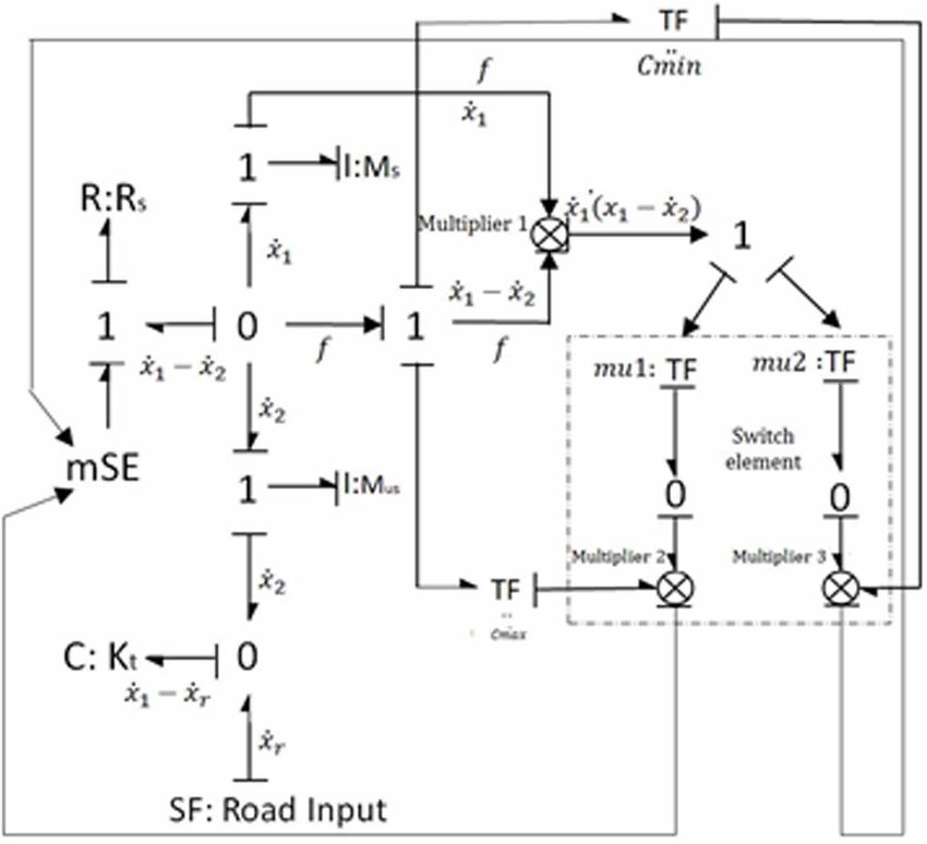
International Journal of System Dynamics Applications
Volume 10 • Issue 4 • October-December 2021

on vehicles are always the primary interest of scientific society (Elkady, Elmarakbi, MacIntyre, &
Alhariri, 2016; Kizito, & Semwanga, 2020; Spichkova, & Hamilton, 2016; Joshi, & Talange, 2016).
However, suspension is the significant member of the vehicle structure which impact the whole vehicle
dynamics. There are various extensions in suspension control was created by various researchers,
whereas suspension quality has been improved.
     Karnopp, et al. (1974) demonstrated the skyhook controller with semi-active suspension
system and compared it with that of a traditional passive system (Karnoop, Crosby, & Hardwood,
1974; Karnoop, 1990). Semi-active suspension system can provide the versatility, flexibility and
higher performance of fully active systems with a miniscule amount of energy while maintaining
the reliability of passive systems. Alanoly and Sankar (1987; 1988) developed the balance logic for
vibration and shock isolation. Liu et al. (2005) studied the “on-off” and “continuous” forms of both
skyhook and balance logic and compared it to adaptive passive damping control system. Shamsi and
Choupani (2008) presented the on-off and continuous skyhook control for half car roll-plane model
and compared the frequency and transient responses with that of a passive system. Strecker et al.
(2015) presented the comparison between three semi-active control algorithms viz. groundhook,
skyhook and modified groundhook and passive system. They were conducted for three different
response time of magnetorheological (MR) damper; 1.5, 8 and 20ms. The outcome of this study
shows that the MR damper with modified groundhook shows better grip for shorter response time
of 1.5 m-s. Bakar et al. (2015) compared skyhook and modified skyhook control algorithms for a
validated with a full car model.
     Zhang et al. (2013) examined the skyhook based semi-active control of full vehicle suspension
system incorporated with MR damper. A 7-DOF full vehicle dynamic model is set up by using the
modified Bouc-wen hysteretic model of MR damper and a modified skyhook control is proposed to
individually control the four MR quarter vehicle sub-systems of the full vehicle. Ikhwan et al. (2015)
studied the skyhook logic for a 7-DOF ride model of an armored vehicle. The skyhook controller
proposed by them consists of an outer loop and an inner loop. The purpose of the outer loop is
to control the body acceleration, pitch acceleration and roll accelerations due to road excitations
whereas, the inner loop controls the damping characteristics. Anand et al. (2015) adopted a fuzzy
logic controller based on skyhook logic to control a semi-active suspension system. The fuzzy logic,
which is a multi-valued logic was introduced in 1965 by Lotfi Zadeh. Kashem, et al. (2015) introduced
a modified continuous skyhook strategy along with adaptive gain that directs the semi-active vehicle
suspension. They have scrutinized 11 sets of suspension parameters and considered a set of parameters
that demonstrated better performance in terms of peak amplitude and settling time.
     Felps-Dezasse, et al. (2017) worked on a fault-tolerant LPV controller for semi-active suspension
which can improve ride comfort with damper malfunctions. The robust controller demonstrates
significant reduction in degradation of comfort. In case of false alarm, the controller shows robust
stability but the ride comfort is significantly compromised. Corno, et al. (2019) designed a control
strategy based on four separate modified sky-hook controllers with a centralized controller to set the
sky-hook algorithms for a full-body super car. Papaioannou et al. (2019) investigated optimization of
different sky-hook controls for semi-active suspension using KEMOGA algorithm. The method allows
to design a system with various performance indices without compromising road holding and ride
comfort. Gupta et al. (2019) worked on hybrid control for semi-active suspension system and found
that a combination of skyhook and groundhook gives better results in terms of vibration isolation.
     This work develop a bond graph models of various semi active control strategies and integrate
this control strategies with semi active suspension system. Further this work extended to compare
some of these strategies (such as continuous skyhook control, on-off skyhook control, on-off balance
control and continuous balance control) with passive system. Numerical simulations have been carried
out for 2-DOF quarter car model with SYMBOLS Sonata® software. The model is subjected to a road
input profile of half single sine bump.

2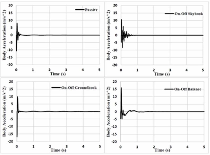
International Journal of System Dynamics Applications
Volume 10 • Issue 4 • October-December 2021
2. MODEL FORMULATION
The model considered in the work is presented in Fig. 1, having 2 DOF quarter car model, where the
conventional damper is replaced with a semi-active controllable damper. The model in Fig. 1 consists
of two masses. The top mass, M s , represents the vehicle body whereas the bottom mass, M u ,
represents the tire. The parallel spring and damper combinations placed in between the vehicle body
and the tire ( k s and cd ) represent the stiffness and damping of the suspension system. The tire
stiffness is shown by the spring kt . x1 , x2 and xin are the vehicle displacement, wheel displacement
and the road input to the quarter car model.
According to Newton’s law, the governing equation of the system can be represented as:
¨
M s x1 ks
x1
x2
cd
x1
x2
0 (1)
¨
M u x 2 ks
x1 x2
cd
x1 x2
kt
x2 xin
0 (2)
The same can be represented in the matrix form as:
¨ x
M s 0
x1
cd cd x1
ks ks 0 1
0 + + x = 0 (3)
M u ¨
c
d cd x2 k
s k s
kt kt 2
x2 xin
A bond graph model of the quarter car vehicle suspension system is developed in SYMBOLS
Sonata® software (Mukherjee, Karmakar, & Samantaray, 2014). The model is shown in Fig. 2. Details
of bond graph modelling is incorporated in Appendix.
3. DESCRIPTION OF VARIOUS CONTROL
STRATEGIES THROUGH BOND GRAPHS
Semi-active damper can be of two types: On-Off and continuously variable. An on-off damper is
swapped between “on” and “off” states of damping according to a suitable control algorithm. A
continuously variable damper is also swapped in between “On -Off” states, but the ‘On’ state damping
coefficient is varied, thus varying the corresponding damping force (Liu, Waters, Brennan, 2005).
Following section describes bond graph model seven control algorithms viz. ‘on-off’ skyhook,
continuous skyhook, on-off balance, continuous balance, on-off groundhook, continuous groundhook
and hybrid control strategies.
3.1. Continuous Skyhook Control
One may consider a 2-DOF system with a skyhook damper as shown in Fig. 1, evaluate the damping
force (Liu, Waters, Brennan, 2005), which may expressed as,
Fsky = csky x1 , (4)
3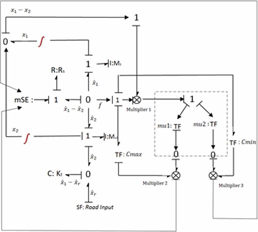
International Journal of System Dynamics Applications
Volume 10 • Issue 4 • October-December 2021
Figure 1. 2-DOF quarter car model with controllable damper
where , Fsky is the skyhook damping force, x1 is the vertical velocity of the vehicle body and csky
of damping for the skyhook damper. The aim is to imitate the force of skyhook damper with a
controllable damper, which is mounted between the vehicle body and the wheel/unsprung mass. As
vibrant energy is absorbed by a possible damper, so it must uphold the inequality of the product of
skyhook damping force and the relative velocity.
Fsa
x1 x2
0. (5)
The required force iscsky x1 , but the skyhook damper can produce this force only when x1 and
x1 − x0 have the same sign. When x1 and x1 − x0 are of different sign, the skyhook damper can
give a force reversing the required control force. It will be good not to produce any force in this
situation. Thus, the ‘continuous’ skyhook control algorithm may be expressed as,
c x , x
x
x
0,
Fsa sky 1 1 1 2 (6)
0, x1
x1
x2
0.
The switching of the damper is regulated by the term x1
x1 x2
, which is the condition
function. ‘On’ state damping force may be expressed as,
4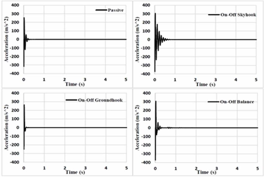
International Journal of System Dynamics Applications
Volume 10 • Issue 4 • October-December 2021
Figure 2. Bond graph model of 2-DOF quarter car suspension system
Fsa csa
x1
x2
, (7)
where csa coefficient of damping for semi active damper. The desired value that csa has to be
assigned to imitate a ‘skyhook’ damper can be obtained by equating Eq. (6) to Eq. (7), which gives
csky x1
9781799858997 , x1
x1
x2
0,
csa
x1
x2
(8)
0, x1
x1
x2
0.
It can be seen from Eq. (8), whenever the relative velocity
x1 x2
is minimal, the desired
damping coefficient increases extremely high and approaches infinity. In general practice, the damping
coefficient of a conventional damper is limited by its physical parameter, i.e., there is an upper limit,
cmax and a lower limit, cmin . Thus, the coefficient damping in Eq. (8) can be obtained as,
c x
max cmin , min sky 1 , cmax , x1
x1
x2
0,
x1
x2
(9)
csa
cmin , x1
x1
x2
0.
5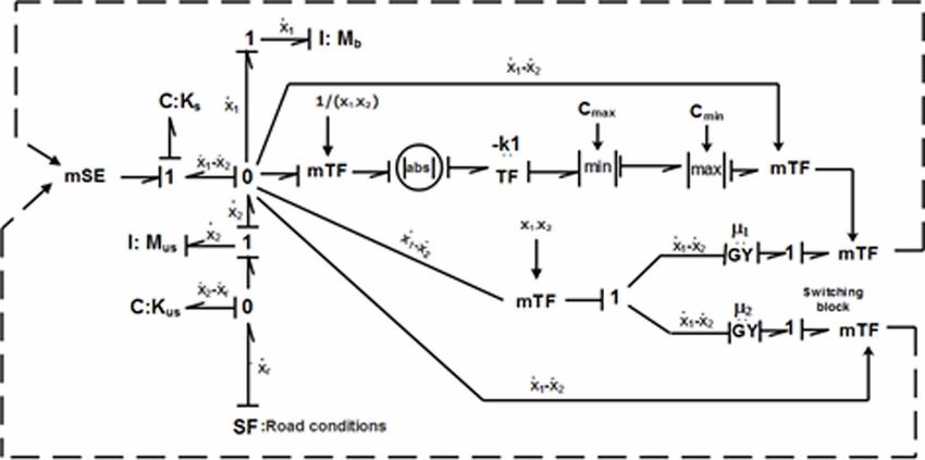
International Journal of System Dynamics Applications
Volume 10 • Issue 4 • October-December 2021
3.2. On-Off Skyhook Control
In case of continuous skyhook, the damping coefficient requires to be varied in continuous matter.
An ‘on-off’ switch is being suggested for simplification (Liu, Waters, Brennan, 2005).
The ‘on-off’ damper generally behaves usual passive damper, which vibrates during the depletion
part of the cycle, but the coefficient of the damping is assumed to be zero when the damping force
produced is in reverse direction to that of a normal skyhook damper. The force damping in case of
on-off control is given by
c
x
x
, x
x
x
0,
Fsa on 1 2 1 1 2 (10)
0, x1
x1
x2
0,
where, con is the coefficient of damping for the ‘On-off’ damper. In a real-world situation, coefficient
of damping with zero value is not possible in the off-state. So, the coefficient of damping is swapped
between a maximum value, cmax and a minimum, cmin . The controller logic is changed accordingly
as
c , x
x
x
0,
csa max 1 1 2 (11)
cmin , x1
x1
x2
0.
At the ‘On’ condition, the coefficient of damping must be greater than ‘Off’ condition of damping,
cmin . ‘Off’ damping constant must be the smallest as possible..
3.3. ‘On-off’ Balance Control Strategy
In control theory, generally ‘balance control’ performs the action of cancellation of spring force
partially by the force of damping. It is also referred to as “relative control” since the control variables
are the relative displacement and the relative velocity between the vehicle body and the wheel.
Considering the 2-DOF system shown in Fig. 2, the acceleration response of the vehicle mass
may be obtained as
¨
1
x1 = − (F + Fd ),
m k
(12)
where Fk and Fd are the force of spring and force of damping respectively. They may be represented
as,
Fk = ks (x 1 − x 2 ) (13)
and
Fd = cd (x 1 − x 2 ), (14)
6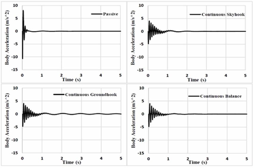
International Journal of System Dynamics Applications
Volume 10 • Issue 4 • October-December 2021
Figure 3. Bond graph model of 2-DOF quarter car suspension system with continuous skyhook controller
where, ks and cd are the stiffness of spring and the coefficient of damping respectively. One may
evaluate the amplitude of the acceleration of the vehicle body, which is excited through a harmonic
excitation and written as (Liu, Waters, Brennan, 2005)
τ
¨ Fk + Fd t0 < t < t0 + ,
x1 =
4 (15)
m τ 3τ
t0 + < t < t0 + ,
2 4
τ τ
¨ Fk − Fd t0 + < t < t0 + ,
x1 = 4 2 (16)
m 3τ
t0 + < t < t0 + τ,
4
¨
where, t0 is the initial time at which acceleration is found to be zero ( x1 = 0 ) and of increasing
trends time τ is the period of vibration. It can be seen from Eq. (25) that the force of damping
contributes to initial increase in the acceleration for two quarters whereas deceleration remain part
of the cycle (Eq. (26)).
The acceleration will be increased whenever the force of spring and force of damper forces
the same direction, which means the relative velocity as well as displacement are having the same
direction (Liu, Waters, Brennan, 2005). A controller logic is employed to ensure the condition as
c (x − x ), (x − x 2 ) (x 1 − x 2 ) ≤ 0,
Fsa = on 1 2 1
(17)
0,
(x 1
− x 2 ) (x 1 − x 2 ) > 0,
7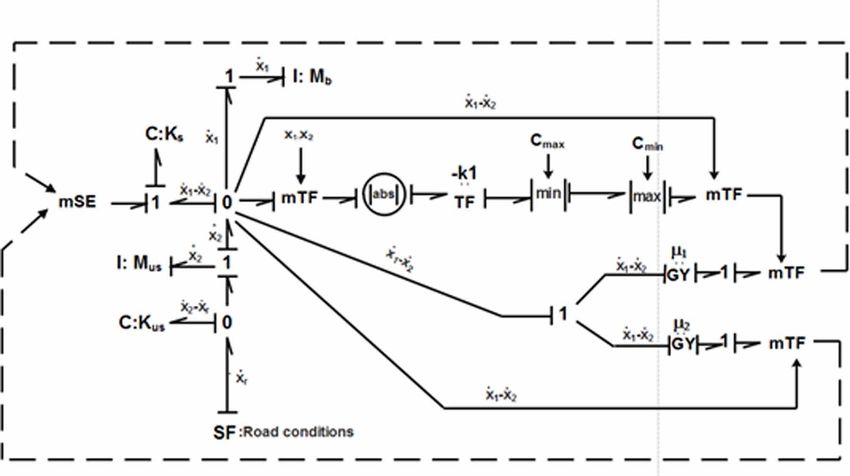
International Journal of System Dynamics Applications
Volume 10 • Issue 4 • October-December 2021
Figure 4. Bond graph model of 2-DOF quarter car suspension system with On/off skyhook control
where, con is the ‘On’ condition coefficient of damping the on-off damper. The applicable algorithm
for coefficient of damping for the ‘on-off’ semi-active damper may be expressed as,
c , (x 1 − x 2 ) (x 1 − x 2 ) ≤ 0,
csa = max (18)
cmin , (x 1 − x 2 ) (x 1 − x 2 ) > 0,
where, cmax and cmin represents the maximum and the minimum condition of damping coefficients
of the ‘on-off’ damper.
3.4. Continuous Balance Control
During the ‘On’, the instantaneous force of damping is rarely balance the instantaneous force of
spring in magnitude. Thus, the excess force will add to the acceleration of the vehicle body. In work
carried out by Liu, et al. (2005), an algorithm of continuous control with varying parameter has been
recommended. In this logic, the damping coefficient is continuously varied on the basis of relative
displacement and desired velocity, in such manner the force of spring and the force of damper balance
out completely in ‘On’ condition. The desired may be expressed as,
8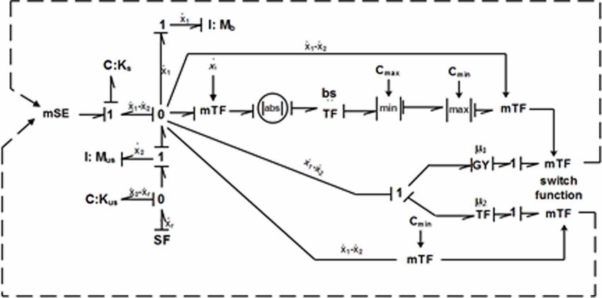
International Journal of System Dynamics Applications
Volume 10 • Issue 4 • October-December 2021
Figure 5. Bond graph model of 2-DOF quarter car suspension system with on/off balance control
−k (x − x 2 ), (x − x 2 ) (x 1 − x 2 ) ≤ 0,
Fsa = s 1 1
(19)
0, (x 1
− x 2 ) (x 1 − x 2 ) > 0.
In such cases the damper sometimes responds like a spring with a negative stiffness in ‘On’
condition. The force of damping is regulated to balance the magnitude of the spring force such that
zero acceleration is produced. The damping coefficient according to this control algorithm can be
expressed as,
−k (x − x )
s 1
C sa
= (x 1 − x 2 )
2
(x 1
− x 2 ) (x 1 − x 2 ) ≤ 0,
(20)
0, (x 1
− x 2 ) (x 1 − x 2 ) > 0
In the Eq. (30), the damping coefficient will approach infinity when (x 1 − x 2 ) → 0 , which is
practically not possible. The damping coefficient has an upper limit and a lower limit on the basis of
9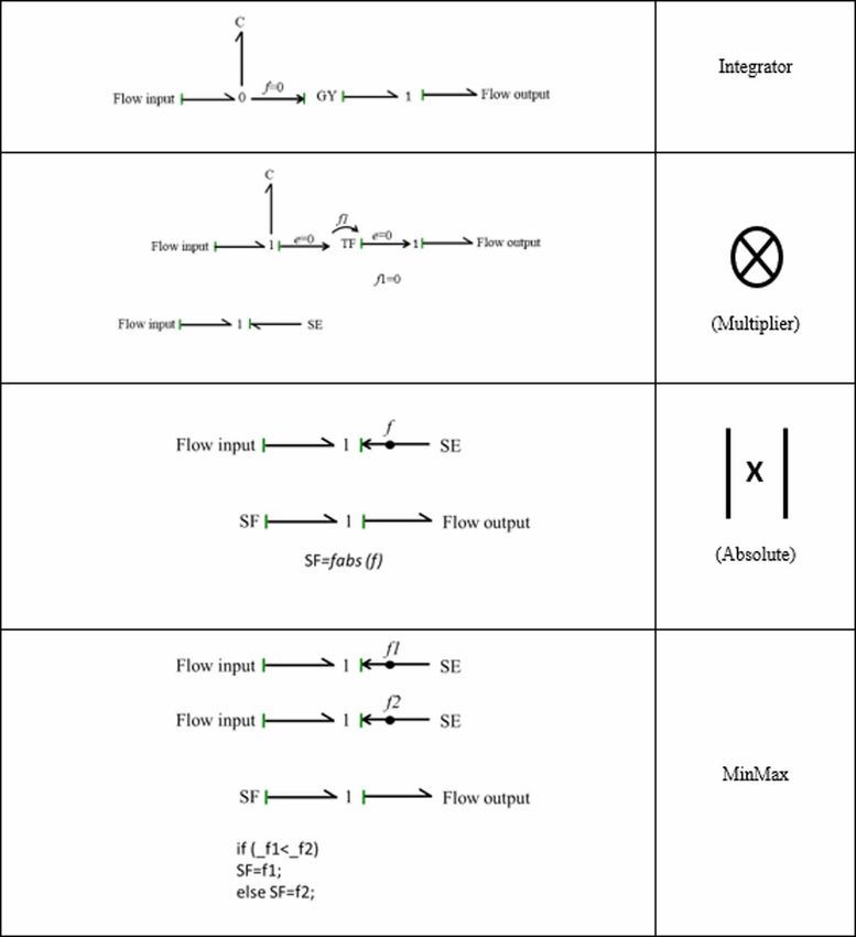
International Journal of System Dynamics Applications
Volume 10 • Issue 4 • October-December 2021
the physical parameter of the damper. Taking into consideration the physical constraints, the damping
coefficient is expressed as
max c , min s ( 1
−k x − x )
=
2
, c ,
max (x − x 2 ) (x 1 − x 2 ) ≤ 0
C sa
min
( x 1 − x 2 )
1
(21)
cmin , (x 1
− x 2 ) (x 1 − x 2 ) > 0
Both the on-off and continuous balance algorithm balance out the damping force and force of
spring partially, if both the forces have opposite signs. In on-state, the on-off logic can generate a
force of damping , which is proportional to the relative velocity across the ‘on-off’ damper. Hence,
it cannot assure that the damping force cancels out the spring force totally.
The force of spring can be partially balanced or may completely balance depending upon the
minimum damping cmin , maximum damping value cmax and the frequency. In case of ‘continuous’
balance control, the force of spring may be balanced by the damping force partially or fully.
3.5. Continuous Groundhook Control
Considering a 2-DOF system with a groundhook damper as shown in Fig. 2, the damping force can
be written as
Fgroundhook = cgnd X 2 , (22)
where,Fgroundhook is the groundhook damping force, x 2 is the velocity of the unsprung mass and cgnd
is the coefficient of damping of the groundhook damper. The aim is to imitate the groundhook force
of damping with a controllable damper, which may be put between the vehicle body and the wheel/
unsprung mass. However, vibration energy can be absorbed by a passive damper. So it must satisfy
the inequality which may be written as,
Fsa (x 1 − x 2 ) ≥ 0. (23)
cgnd x2 , but this force can be provided by semi active damper when x2
The required force is
and x1 − x2 have the opposite sign. When x2 and x1 − x2 are of same sign, the damper can give a
force reverse the required control force. It is useful not to excite any force in this situation. Thus, the
‘continuous’ control logic may be expressed as,
c x , −x (x − x ) ≥ 0,
Fsa = gnd 2 2 1 2
(24)
0 −x 2 (x 1 − x 2 ) < 0.
The switching of the damper is regulated by the term −x 2 (x 1 − x 2 ) , which is the condition
function. On state force of damping may be expressed as,
Fsa = cd (x 1 − x 2 )
(25)
10International Journal of System Dynamics Applications
Volume 10 • Issue 4 • October-December 2021
Figure 6. Bond graph model of 2-DOF quarter car suspension system with continuous balance control
where, cd coefficient of damping for the semi active damper. The value, which can be assigned as
cd have to imitate a groundhook damper can be obtained by equating Eq. (24) to Eq. (25), which
gives
c x
gnd 2
−x 2 (x 1 − x 2 ) ≥ 0,
cd = (x 1 − x 2 ) (26)
0, −x 2 (x 1 − x 2 ) < 0.
Again, it can be seen from Eq. (26) that whenever the value of relative velocity
x1 x2
is
marginally small, the desired coefficient of damping incases abruptly and approaches to infinity.
Generally, the coefficient of damping of a conventional damper is limited by its physical parameter,
i.e., there is an upper limit, cmax and a lower limit, cmin . . Thus, the coefficient of damping in Eq.
(36) may be expressed as,
max c , min C gnd X 2 , c −x (x − x ) ≥ 0
max
C d min (x 1 − x )
2 1 2
, (27)
cmin . −x 2 (x 1 − x 2 ) < 0
3.6. On-Off Groundhook Control For Quarter Car Vehicle
It has been seen that the ‘on-off’ damper behaves like a conventional passive damper during the
vibration depletion part of the vibration cycle, but the coefficient of damping is considerd to be
zero whenever the force of damping produced is in reverse direction to that of an ideal groundhook
damper. The damping force in case of on-off control is given by
11International Journal of System Dynamics Applications
Volume 10 • Issue 4 • October-December 2021
con (x 1 − x 2 ), −x 2 (x 1 − x 2 ) ≥ 0,
Fsa = (28)
0, −x 2 (x 1 − x 2 ) < 0,
where, con is the ‘on-state’ coefficient of damping of the ‘on-off’ damper. In a realistic situation, it
is not possible to have a zero coefficient of damping a zero damping in ‘off’ state. So, the coefficient
of damping is swapped between a maximum value, cmax and a minimum value, cmin . The logic of
controller algorithm is changed accordingly as,
c , −x (x − x ) ≥ 0,
cd = max 2 1 2
(29)
cmin , −x 2 (x 1 − x 2 ) < 0.
The ‘On’ condition coefficient of damping, cmax must be much longer than the ‘Off’ condition
coefficient of damper, cmin . The ‘off’ condition constant of damping must be approached to the
smallest value possible..
3.7. Hybrid Control Strategy
Hybrid control strategies can be developed by combining two or more of the above control strategies.
They can provide the benefit of both the control strategies and hence may provide better performance
in terms of vibration isolation as well as vehicle handling.
3.7.1. Hybrid Skyhook-Groundhook Control
This logic is intended at reducing both the body acceleration and the dynamic tire force. The sprung
mass here is considered to be linked to a hypothetical damper which is connected to an inertial reference
in sky, whereas the unsprung mass has a damper which is connected to a reference point in ground.
The control algorithm is obtained by combining both skyhook and groundhook control algorithms.
Fhybrid SH GH
Fskyhook
1 Fgroundhook (30)
where, Fhybrid − SH −GH is the damping force of the hybrid controller, Fskyhook is the skyhook damping
force, Fgroundhook is the groundhook damping force and α is the weighing factor to adjust comfort
or handling,
0,1
(Shamsi & Choupani, 2008). The skyhook damping force is controlled with
the on-off skyhook strategy as discussed before and the groundhook force is controlled by the on-off
groundhook logic respectively.
3.7.2. Hybrid Skyhook-Balance Control
Similar to above hybrid logic, other hybrid strategies can be developed by combining two or more
control strategies. We can combine skyhook and balance logic to give the hybrid control logic as
shown below,
Fhybrid −SH −B = βFskyhook + (1 − β ) Fbalance (31)
12International Journal of System Dynamics Applications
Volume 10 • Issue 4 • October-December 2021
Figure 7. Bond graph model of 2-DOF quarter car suspension system with continuous ground hook
where, Fhybrid −SH −B is the damping force of hybrid controller, Fbalance is the balance control force and
β is the weighing factor to adjust the level of skyhook control or balance control. If β is set to 1,
the control will be purely skyhook control, whereas, if β is set to 0, it will be a pure balance control.
Similar as before, the skyhook and balance damping forces are controlled by the on-off skyhook and
on-off balance control algorithms.
3.7.3. Hybrid Groundhook-Balance Control
Groundhook and balance control logics were fused together to achieve a hybrid control strategy as
shown below,
Fhybrid −GH −B = γFgroundhook + (1 − γ ) Fbalance (32)
where, Fhybrid −GH −B is the damping force of hybrid controller and γ is the weighing factor to adjust
the level of groundhook control or balance control. If γ is set to 1, the control will be purely
groundhook control, whereas, if γ is set to 0, it will be a pure balance control. Here, the groundhook
damping force is regulated by the on-off groundhook logic whereas, balance damping force is
controlled with on-off balance logic.
4. ROAD INPUT
A half sine bump profile is used as road input to carry out the simulation of the vehicle model. The
transient input chosen may be represented as (Mukherjee, Karmakar, & Samantaray, 2014, p. 567)
13International Journal of System Dynamics Applications
Volume 10 • Issue 4 • October-December 2021
Table 1. Semi Active hybrid control algorithm(s)
Hybrid Damping force Damping Condition function
damper coefficient
type
HS-1 Hybrid On-state Cd,sky=Cmax
Skyhook- Fhybrid −SH −GH X 1 (X 1 − X 2 ) ≥ 0
Groundhook = αFskyhook
control Ù
+ (1 − α) Fgroundhook −X 2 (X 1 − X 2 ) ≥ 0
Cd,ground=Cmax
Off-state Cd,sky=Cmin
X 1 (X 1 − X 2 ) < 0
Ù
Cd,ground=Cmin −X 2 (X 1 − X 2 ) < 0
HS-2 Hybrid On- state Cd,ground=Cmax Ù
Fhybrid −GH −B = γFgroundhook
Groundhook- −X 2 (X 1 − X 2 ) ≥ 0
Balance + (1 − γ )
control
Fbalance Cd,balance=Cmax (X − X1 ) (X 1 − X 2 ) ≤ 0
1
Off-state Cd,ground=Cmin Ù
−X 2 (X 1 − X 2 ) < 0
Cd,balance=Cmin (X 1
− X1 ) (X 1 − X 2 ) > 0
HS-3 Hybrid On-state Cd,sky=Cmax
Skyhook- Fhybrid −SH −B = βFskyhook X 1 (X 1 − X 2 ) ≥ 0
Balance + (1 − β )
control
Cd,balance=Cmax (X − X1 ) (X 1 − X 2 ) ≤ 0
Fbalance 1
Off-state Cd,sky=Cmin
X 1 (X 1 − X 2 ) < 0
Cd,balance=Cmin (X 1
− X1 ) (X 1 − X 2 ) > 0
V L
h * sin PI * * t , for 0 ≤ t ≤
y = L V (33)
0, otherwise
where, h is the height of the bump, which is 0.1m; L is the length of the bump, which is 0.3m; t
is the time and V is the velocity of the vehicle.
14International Journal of System Dynamics Applications
Volume 10 • Issue 4 • October-December 2021
5. VALIDATION OF CONTROL STRATEGIES
The frequency and transient analysis of the systems are investigated. The results are demonstrated for
different speeds (i.e. 60, 80,100 Kmph) in transient state. Simulation work has been carried out on
Matlab® or Simulink. The parameters (Goncalves, 2001) used for the simulation are shown in Table 2.
In this work, the response of the system in terms of body acceleration, body displacement or heave and
tire deflection are evaluated and used as performance index. For random input, acceleration-frequency
response and power spectral density are also plotted. The results are discussed in the following section.
5.1. Transient Analysis of Quarter Car
The response dynamics for transient input are evaluated for all control strategies and also for a passive
suspension system. Acceleration time response and frequency response are obtained for sprung mass
and un-sprung mass, which has to be considered for evaluation of system performance.
5.1.1. Performance Of On-Off Control Strategies
The performance of the different on-off control algorithms are presented in this section. The 2-DOF
quarter car model has been subjected to a half sine bump road input and different on-off logics such
as skyhook, balance and groundhook strategies have been applied to control the damping force of
the suspension system. The results were obtained in terms of body acceleration, unsprung mass
acceleration, body displacement and transmissibility, both in time and frequency domain.
5.1.1.1. Body Acceleration
Fig. 8 shows the body acceleration vs time plot for the passive suspension system and semi-active
system controlled with different on-off strategies. Fig. 8 (a) shows the acceleration for the passive
system. The maximum amplitude of body acceleration reached with all on-off control strategies is
more than that of a passive suspension system, which is clearly depicted from Fig 8 (b-d). However,
the settling time for the passive suspension system is approximately 2.5 seconds whereas, that of an
on-off skyhook logic is found to be approximately 1 second. The settling time has been reduced by
60% approximately. But there is an added disadvantage of the on-off skyhook control. Whenever
the condition function i.e., the product of the absolute velocity of the sprung mass and the relative
velocity across the suspension, changes sign, the damper is switched between the on and the off
states. Hence, there is a sudden rise in the amplitude of body acceleration and the passenger or the
driver will feel a sudden jerk, which can be considered uncomfortable. The on-off groundhook logic
does not show such sudden jerks as shown in Fig. 8 (c). But the settling time for this logic is very
large and hence, the vibration can be felt for a longer duration. In case of on-off balance logic, there
is significant reduction in the sudden jerks, but the settling time is almost same as that for a passive
system as depicted in Figure 8 (d).
5.1.1.2. Unsprung Mass Acceleration
Fig. 9 demonstrates the response of the system’s un-sprung mass acceleration in time domain. Un-
sprung acceleration of passive system is shown in Fig 9 (a). It can be shown from Fig. 9 (b) that the
on-off skyhook logic has increased magnitude of the unsprung mass acceleration as well as more
settling time. The groundhook logic gives better performance in this regard. The magnitude is less
than that of a passive system or the other two control strategies as can be seen in Fig. 9 (c).
The settling time is also less in case of on-off groundhook control and is approximately 0.25
seconds, whereas the settling time for passive system is about 0.5 seconds. This is due to the inherent
nature of groundhook logic, which gives better road holding as compared to other logics. In Fig. 9
(d), on-off balance logic has also increased magnitude at the beginning but immediately dampens
out to small values. But the settling time is more in this case.
5.1.1.3. Transmissibility
15International Journal of System Dynamics Applications
Volume 10 • Issue 4 • October-December 2021
Table 2. Model Parameter for 2-DOF quarter car model (Goncalves, 2001)
Parameter Value Unit Parameter Value Unit
Ms 365 kg cmin 258 Ns/m
Mu 40 kg cmax 2838 Ns/m
ks 19960 N/m csky 1290 Ns/m
kt 175500 N/m cgnd 1290 Ns/m
Figure 10 represents the transmissibility of acceleration in between sprung mass and unsprung mass
in frequency domain. From figure, it is obvious that the on-off skyhook logic has shown extreme
performance regarding reducing transmissibility of vibration from unsprung to sprung mass. However,
the transmissibility is found to be more for groundhook and balance logics. Maximum value of
transmissibility achieved by passive system is approximately 0.22 whereas, the same for skyhook is
less than 0.1. On the contrary, groundhook and balance logics have maximum value of transmissibility
at 0.6 and 0.75 respectively.
5.1.2. Performance of Continuous Control Strategies
The results for continuous control algorithms have been presented in this section.
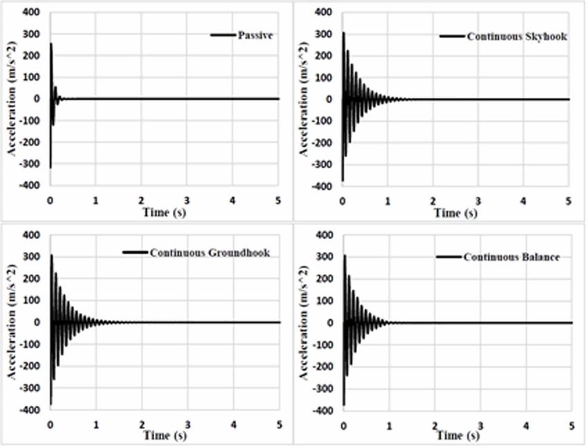
5.1.2.1. Body Acceleration
The body acceleration response of different continuous control strategies in time domain, which
is shown in Fig 10. It can be observed from Fig. 11 that for all the three continuous strategies, the
maximum magnitude of acceleration has been reduced to almost half of that of a passive suspension
system. However, the settling time has been compromised in the case of continuous strategies and a
continuous vibration reducing in magnitude over time can be felt. The settling time for continuous
skyhook and continuous balance logics have been found to be in between 3-3.5 seconds as can be
seen in Fig. 11 (b) and (d) respectively, whereas that for passive system is 2.5 seconds (Fig. 11 (a)).
Groundhook logic has poor settling time, a periodic disturbance is present for a prolonged duration
in case of continuous groundhook logic (Fig. 11 (c)).
5.1.2.2. Un-Sprung Mass Acceleration
Fig. 12 displays the acceleration response of the un-sprung mass of the vehicle model in time domain.
It can be seen from figure that for all the three continuous control strategies, the magnitude as well as
the settling time has been compromised for the unsprung mass acceleration. Whereas the amplitude
is slightly higher in each case, the settling time is more. The wheel of the vehicle has to undergo a
prolonged vibration before coming to a steady state.
5.1.2.3. Transmissibility
The transmissibility of acceleration at 60kmph has been shown in Figure 13.
It can be observed that the transmissibility of acceleration is more for all the three continuous
strategies. Maximum transmissibility for continuous balance is found to be comparatively less than
skyhook and groundhook logics and is approximately 0.25. For continuous skyhook logic, the value
16International Journal of System Dynamics Applications
Volume 10 • Issue 4 • October-December 2021
Figure 8. Body acceleration vs time plot of quarter car at 60 kmph for (a) passive suspension system (b) on-off skyhook control
(c) on-off groundhook control and (d) on-off balance control
of maximum transmissibility is found to be approximately 0.4 whereas, for continuous groundhook,
it’s even more.
5.1.3. Performance of Hybrid Control Strategies
The performance of the quarter car model has been carried out for four different hybrid combinations,
which are follows; - i) Hybrid skyhook-groundhook (HY-SH-GH), ii) Hybrid skyhook-balance (HY-
SH-B) and iii) Hybrid groundhook-balance (HY-GH-B). The response of semi active suspension with
different control strategies has been presented in this research work.
5.1.3.1. Body Acceleration
Fig. 14 demonstrates the acceleration response of the sprung mass of the quarter vehicle controlled
by different hybrid strategies. The weighing factors for all four hybrid logics have been optimized
by hit and trial method and final values are presented in Table 3 below.
It can be observed from Fig. 14 (b) that the response of HY-SH-GH logic is better in case of both
magnitude and settling time respectively. However, the magnitude of acceleration is maximum for
the HY-GH-B combination. The settling time is almost better for HY-SH-GH logic than HY-SH-B
and HY-GH-B logics, which can be seen in Fig. 14 (c) and (d). The sudden jerks due to uneven road
in on-off skyhook logic has been significantly reduced in case of hybrid strategies. HY-SH-GH logic
has less severe sudden jerks when the condition functions have changed their sign as compared to
other hybrid logics. The settling time for HY-SH-GH logic has been found to be approximately 0.5
seconds which is 80% less than the passive suspension system and 50% less than simple on-off skyhook
logic. Moreover, the sudden jerks caused by the switching of the damper in between the on and the
off state as the condition functions change their direction is less severe in case of the HY-SH-GH
strategy. The severity of the jerks is directly related to passenger’s comfort. HY-SH-GH logic can
17International Journal of System Dynamics Applications Volume 10 • Issue 4 • October-December 2021 Figure 9. Unsprung mass acceleration vs time plot of quarter car at 60 kmph for (a) passive suspension system (b) on-off skyhook control (c) on-off groundhook control and (d) on-off balance control Figure 10. Transmissibility of acceleration of quarter car at 60 kmph for on-off logics 18
International Journal of System Dynamics Applications
                                                                             Volume 10 • Issue 4 • October-December 2021

Figure 11. Body acceleration vs time plot of quarter car at 60 kmph for (a) passive suspension system (b) continuous skyhook
control (c) continuous groundhook control and (d) continuous balance control

thus provide a better comfort as compared to on-off skyhook logic, which provides numerous jerks
before coming to a steady state position.
5.1.3.2. Unsprung Mass Acceleration
Acceleration response of un-sprung mass in time domain has been shown in Fi g. 15.Results have
shown that the acceleration response of the un-sprung mass is best for the hybrid combination of
groundhook and balance logic (Fig. 15 (d)). The magnitude as well as the settling time is minimum for
this strategy. Other strategies have a slightly higher settling time and the magnitude of acceleration is
also comparatively more than HY-GH-B as well as passive system. The settling time is approximately
0.5 seconds for passive systems and also for all hybrid strategies except for HY-GH-B, for which the
settling time is 0.25 seconds which is 50% less. The magnitude is maximum for the HY-SH-B logic
as can be seen in Figure 15 (c).
5.1.3.3. Body Displacement
Body displacement vs time for speed of 60kmph has been plotted and shown in Fig. 16.It can be
observed from Fig. 16 (b) that the HY-SH-GH logic has the best performance regarding displacement
response as the maximum amplitude achieved is less for this logic. Other two logics have more
magnitude of body displacement aswell as the settling time. The combination of skyhook-groundhook
has less settling time as well.
5.1.3.4 Transmissibility
Figure 17 presents the transmissibility of acceleration between sprung and unsprung masses for
all hybrid control logics. It is found that the HY-SH-GH logic has better performance in terms of
transmissibility of acceleration. The maximum transmissibility achieved is much less than that of a
passive system. For this logic, the maximum transmissibility is found to be approximately about 0.07

                                                                                                                         19
International Journal of System Dynamics Applications Volume 10 • Issue 4 • October-December 2021 Figure 12. Unsprung mass acceleration vs time plot of quarter car at 60 kmph for (a) passive suspension system (b) continuous skyhook control (c) continuous groundhook control and (d) continuous balance control Figure 13. Transmissibility of acceleration of quarter car at 60 kmph for continuous logics 20
International Journal of System Dynamics Applications
                                                                                 Volume 10 • Issue 4 • October-December 2021

Table 3. Optimized value of weighing factors for hybrid logic

            Hybrid logic                 α                                β                             γ

             HY-SH-GH                                0.85                            ---                           ---

              HY-SH-B                                 ---                            0.4                           ---

              HY-GH-B                                 ---                            ---                          0.45

Figure 14. Body acceleration vs time plot of quarter car at 60 kmph for (a) Passive (b) HY-SH-GH (c) HY-SH-B and (d) HY-GH-B control

whereas, for a passive system, maximum transmissibility is found to be around 0.22. For HY-SH-B
and HY-GH-B logics, maximum transmissibility is found to be approximately 0.25 which is even
more than the passive system.

                                                                                                                                 21
International Journal of System Dynamics Applications Volume 10 • Issue 4 • October-December 2021 Figure 15. Unsprung acceleration vs time plot of quarter car at 60 kmph for (a) Passive (b) HY-SH-GH (c) HY-SH-B and (d) HY- GH-B control 22
International Journal of System Dynamics Applications
                                                                                 Volume 10 • Issue 4 • October-December 2021

Figure 16. Body displacement vs time plot of quarter car at 60 kmph for (a) Passive (b) HY-SH-GH (c) HY-SH-B and (d) HY-GH-B control

Figure 17. Transmissibility of acceleration of quarter car at 60 kmph for hybrid logics

                                                                                                                                 23
International Journal of System Dynamics Applications
Volume 10 • Issue 4 • October-December 2021
6. CONCLUSION
The following conclusion have been made in this paper.
• The dynamic model of quarter car suspension model has been constructed through bond graph
technique.
• Four different semi active conrtrol strategies have been presented through bond graph technique.
• The dynamic behavior of quarter car system also analyzed with three different hybrid control
strategies.
• The response of body displacement, body acceleration, wheel displacement and wheel
displacement are presented in this study.
• The comfort of the passenger car further be analysed with the road experiment, as the value obtain
in simulation is sometimes higher than the real one, due to the random error used.
• It is found that the HY-SH-GH logic has better performance in terms of transmissibility of
acceleration.
24International Journal of System Dynamics Applications
Volume 10 • Issue 4 • October-December 2021
REFERENCES
Agostinacchio, M., Ciampa, D., & Olita, S. (2014). The vibrations induced by surface irregularities in road
pavements – a Matlab® approach, Springer. European Transport Research Review, 6(3), 267–275. doi:10.1007/
s12544-013-0127-8
Alanoly, J., & Sankar, S. (1987). A new concept in semi-active vibration isolation, American Society of
Mechanical Engineers. Journal of Mechanisms, Transmissions, and Automation in Design, 109(2), 242–247.
doi:10.1115/1.3267444
Alanoly, J., & Sankar, S. (1988). Semi-active force generators for shock isolation. Journal of Sound and Vibration,
126(1), 145–156. doi:10.1016/0022-460X(88)90404-X
Amin, M. H. I. M., Hudha, K., Kadir, Z. A., & Amer, N. H. (2015). Skyhook Control for 7 DOF Ride Model Of
Armored Vehicle Due To Road Disturbance. IEEE. doi:10.1109/ASCC.2015.7244494
Anand, R. R., Shrivastava, S., & Trikhande, M. W. (2015). Modelling and Analysis of Skyhook and Fuzzy Logic
Controls in Semi-Active Suspension System. In 2015 International Conference on Industrial Instrumentation
and Control (ICIC). College of Engineering Pune. doi:10.1109/IIC.2015.7150838
Bakar, S. A. A., Samin, P. M., Jamaluddin, H., Rahman, R. A., & Sulaiman, S. (2015). Semi Active Suspension
System Performance under Random Road Profile Excitations. International Conference on Computer,
Communication, and Control Technology.
Bessinger, F. H., Cebon, D., & Cole, D. J. (1995). Force control of a semi-active damper. J.Veh. Syst. Dyn, 24(9),
695–723. doi:10.1080/00423119508969115
Carter, A. K. (1998). Transient Motion Control of Passive and Semi-active Damping for Vehicle Suspensions
(M. S. Thesis). Virginia Polytechnic Institute and State University.
Corno, M., Galluppi, O., Panzani, G., Sinigaglia, A., Capuano, P., Cecconi, J., & Savaresi, S. M. (2019). Design
and Validation of a Full Body Control Semi-Active Suspension Strategy for a Super Car. IFAC-PapersOnLine,
52-5(5), 667–672. doi:10.1016/j.ifacol.2019.09.106
Dash, D. K. (2015). Over 11,000 people killed by potholes, speed breakers last year. The Times of India Report.
https://timesofindia.indiatimes.com/india/Over-11000-people-killed-by-potholes-speed-breakers-last-year/
articleshow/48950267.cms
Elkady, M., Elmarakbi, A., MacIntyre, J., & Alhariri, M. (2016). Multi-Body Integrated Vehicle-Occupant
Models for Collision Mitigation and Vehicle Safety using Dynamics Control Systems. International Journal of
System Dynamics Applications, 5(2), 80–122. doi:10.4018/IJSDA.2016040105
Felps-Dezasse, M., Svaricek, F., & Brembeck, J. (2017). Damper Fault-Tolerant Linear Parameter-Varying
Semi-Active Suspension Control. IFAC-PapersOnLine, 50-1(1), 8592–8599. doi:10.1016/j.ifacol.2017.08.1425
Goncalves, F. D. (2001). Dynamic Analysis of Semi-Active Control Techniques for Vehicles Application (M. S.
Thesis). Dept. of Mechanical Engineering, Virginia Polytechnic Institute and State University.
Granlund, J. (2012). Vehicle and Human Vibration due to Road Condition. ROADEX IV Project. EU Northern
Periphery Programme.
Gupta, A., Bharadwaj, N., & Upadhyaya, S. (2019). Development of Hybrid Control Algorithm for Improvement
of performance of Semi-Active Suspension System. World Journal of Modelling and Simulation, 15(1), 53–63.
Joshi, S., & Talange, D. B. (2016). Fault Tolerant Control of an AUV using Periodic Output Feedback with
Multi Model Approach. International Journal of System Dynamics Applications, 5(2), 41–62. doi:10.4018/
IJSDA.2016040103
Karnopp, D. C. (1990). Design principles for vibration control systems using semi-active dampers, American
Society of Mechanical Engineers. Journal of Dynamic Systems, Measurement, and Control, 112(3), 448–455.
doi:10.1115/1.2896163
Karnopp, D. C., Crosby, M. J., & Harwood, R. A. (1974). Vibration control using semi-active force
generators. American Society of Mechanical Engineers. Journal of Engineering for Industry, 96(2), 619–626.
doi:10.1115/1.3438373
25International Journal of System Dynamics Applications Volume 10 • Issue 4 • October-December 2021 Kashem, S. B. A., Ektesabi, M., & Nagarajah, R. (2015). Comparison between different sets of suspension parameters and introduction of new modified skyhook control strategy incorporating varying road condition. Vehicle System Dynamics, 50(7), 1173–1190. doi:10.1080/00423114.2012.659743 Kizito, A., & Semwanga, A. R. (2020). Modeling the Complexity of Road Accidents Prevention: A System Dynamics Approach. International Journal of System Dynamics Applications, 9(2), 24–41. doi:10.4018/ IJSDA.2020040102 Krasnicki, E. J. (1980). Comparison of analytical and experimental results for semi-active vibration isolator. Shock and Vibration Bulletin, 50, 69–76. Krasnicki, E. J. (1980). The experimental performance of an “on-off” active damper. Proceedings of the 51st Shock and Vibration Symposium. Liu, Y., Waters, T. P., & Brennan, M. J. (2005). A comparison of semi-active damping control strategies for vibration isolation of harmonic disturbances. Journal of Sound and Vibration, 280(1-2), 21–39. doi:10.1016/j. jsv.2003.11.048 Mukherjee, A., Karmakar, R., & Samantaray, A. K. (2014). Bond Graph in Modeling, Simulation and Fault Identification. I. K. International Publishing House Pvt. Ltd. Nguyen, Q. H., & Choi, S. B. (2009). Optimal design of MR shock absorber and application to vehicle suspension. Smart Materials and Structures, 18(3), 035012. doi:10.1088/0964-1726/18/3/035012 Papaioannou, G., & Koulocheris, D. (2019). Multi-objective optimization of semi-active suspensions using KEMOGA algorithm. Engineering Science and Technology, an International Journal, 22, 1035-1046. Rakheja, S., & Sankar, S. (1985). Vibration and shock isolation performance of a semi-active “on-off” damper. American Society of Mechanical Engineers, Journal of Vibration, Acoustics, Stress, and Reliability in Design, 107(4), 398–403. doi:10.1115/1.3269279 Road Accidents in India. (2012). Government of India, Ministry of Road Transport and Highways, Transport Research Wing. Author. Road Accidents in India. (2013). Government of India, Ministry of Road Transport and Highways, Transport Research Wing. Author. Shamsi, A., & Choupani, N. (2008). Continuous and Discontinuous Shock Absorber Control through Skyhook Strategy in Semi-Active Suspension System (4DOF Model). World Academy of Science, Engineering and Technology, International Journal of Mechanical, Aerospace, Industrial Mechatronic and Manufacturing Engineering, 2(5), 697–701. Simon, D. E. (1998). Experimental Evaluation of Semiactive Magnetorheological Primary Suspensions for Heavy Truck Application (M. S. Thesis). Dept. of Mechanical Engineering, Virginia Polytechnic Institute and State University. Sireteanu, T., Stancioiu, D., & Stammers, C. W. (2002). Use of magnetorheological fluid dampers in semi-active driver seat vibration control. ACTIVE 2002. Spichkova, M., & Hamilton, A. R. (2016). Dynamic Decision Making System for Public Transport Routes. International Journal of System Dynamics Applications, 5(3), 47–70. doi:10.4018/IJSDA.2016070103 Strecker, Z., Mazůrek, I., Roupec, J., & Klapka, M. (2015). Influence of MR damper response time on semiactive suspension control efficiency. Meccanica, 50(8), 1949–1959. doi:10.1007/s11012-015-0139-7 Strydom, A., & Els, S. (2014). The Applicability of Hybrid Control to a Small Off-Road Vehicle without a Differential. Proceedings of the ASME 2014 International Design Engineering Technical Conferences & Computers and Information in Engineering Conference IDETC/CIE 2014. doi:10.1115/DETC2014-34344 Zhang, H., Wang, E., Min, F., Rakheja, S., & Su, C. (2013). Skyhook-based Semi-active Control of Full-vehicle Suspension with Magneto-rheological Dampers. Chinese Journal of Mechanical Engineering, 26(3), 498–505. doi:10.3901/CJME.2013.03.498 26
International Journal of System Dynamics Applications
                                                                                 Volume 10 • Issue 4 • October-December 2021

APPENDIX I.

The language of bondgraphs aspires to express general class of physical systems through power
interactions. The factors of power, i.e., Effort and Flow, have different interpretations in different
physical domains. Yet, power can always be used as a generalized co-ordinate to model coupled
systems residing in several energy domains. In bondgraphs, one needs to recognize only four groups
of basic symbols, i.e., three basic one port passive elements inertance (I), capacitance (C), and
resistance (R); two basic active elements source of effort (SE), and source of flow (SF); two basic
two port elements gyrator (GY), and transformer (TF); and two basic junctions i.e., constant effort
junction (0), and constant flow junction (1). The basic variables are effort (e), flow (f), time integral
of effort (P) and the time integral of flow (Q).

Figure 18. Definition of Bondgraph Elements with integral causality

                                                                                                                         27
International Journal of System Dynamics Applications Volume 10 • Issue 4 • October-December 2021 APPENDIX II. Description of Capsule element The dynamical system can be segmented into small groups, which is named as capsules. The description of capsule elements used in bondgraph models are presented in Figure 19. Figure 19a. Description of capsule element 28
International Journal of System Dynamics Applications
                                                                        Volume 10 • Issue 4 • October-December 2021

Figure 19b. Description of capsule element

Ashish Gupta received his PhD from Delhi Technological University in July 2018. After PhD he has joined assistant
professor in G. L Bajaj Institute of Technology and Management, Greater Noida. His research areas are vehicle
modeling, system dynamics, and computer simulation.

Nilanjan Bharadwaj presently working as an assistant professor in Department of Mechanical Engineering, University
of Petroleum and Energy Studies, Dehradun. He completed his masters from Delhi Technological University. His
research areas are vehicle modelling, suspension design.

Vikas Rastogi is a professor in mechanical engineering department, Delhi technological university. He did his
PhD from IIT Kharagpur. He is expertise in the areas of System modeling, vehicle modeling, computer simulation,
rotor dynamics

                                                                                                                29
You can also read