Grand Terminal - Safety instructions for firmware V.4 TOTAL NIGHTMARE/03.02.2021
←
→
Page content transcription
If your browser does not render page correctly, please read the page content below

Grand Terminal

   Safety instructions for firmware V.4 TOTAL NIGHTMARE/03.02.2021
First things first

RTFM – be so kind and read the manual. It will provide you with the information you need to fully indulge in
the module you just purchased – for which we like to thank you.
Enjoy your sound experiences, dear sonic traveller.

Beginning from the product's purchase date a 1-year warranty is guaranteed for each product in case of any manufactur-
ing errors or other functional deficiencies during runtime.
The warranty dœs not apply in case of:
• damage caused by misuse
• mechanical damage arising from careless treatment (dropping, vigorous shaking, mishandling, etc.)
• damage caused by liquids or powders penetrating the device
• heat damage caused by overexposure to sunlight or heating
• electric damage caused by improper connecting

Visit us:
http://endorphin.es
http://youtube.com/user/TheEndorphines
http://facebook.com/TheEndorphines

Drop us a line:
info@endorphin.es

FURTH BARCELONA, S.L.
VAT ID:ES B66836487

                                   © 2013-2021 – Endorphin.es – International Airways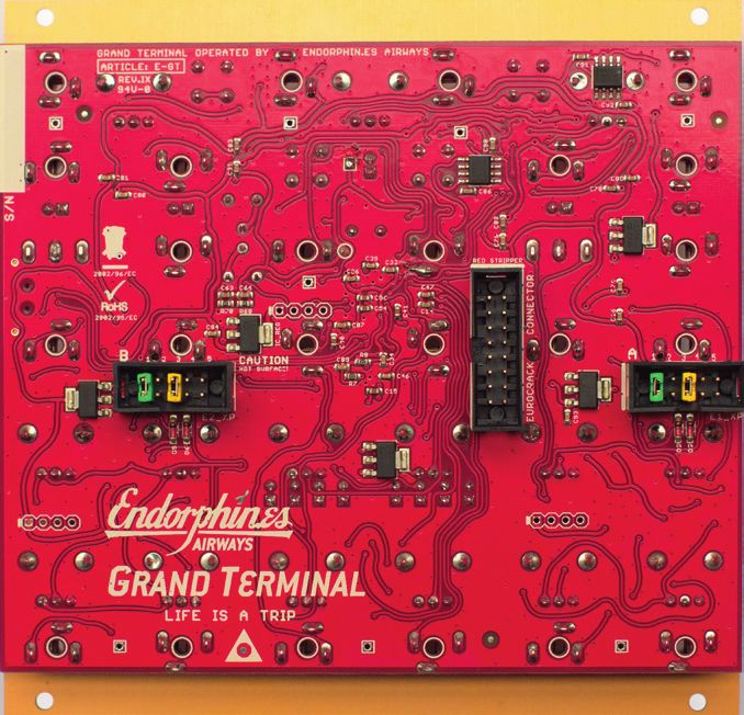
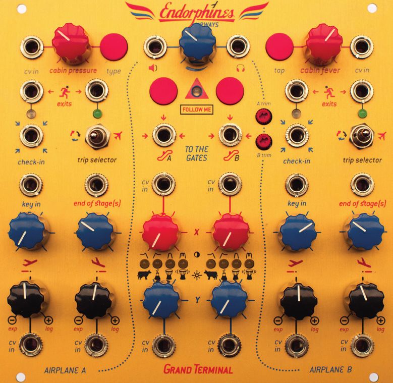
GRAND TERMINAL OPERATED BY ENDORPHIN.ES AIRWAYS

LIFE IS A TRIP

• 26 HP, 1” in depth – super slim and Shuttle friendly
• Dual multi-mode filter (ladder, diode, vactrol, state-variable lp/hp/bp and comb) in dual, stereo and serial modes
• Dual looping/AD/ASR envelope generator that acts as band-limited oscillator when cycling at linear slopes
• Stereo “Cabin Pressure” processor with different ambient effects: from shimmered halls and reverberations to a spring
  simulation over tape/ping-pong delays to a chorus
• Separate mono modular level output and stereo line level output for direct line recording or driving the headphones.
• Easy firmware update via USB
• And of course fully compatible with GatewayT_XP
• I/O: 48 kHz 16 bit audio

                                    © 2013-2021 – Endorphin.es – International Airways                             page 1 of 18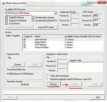
WELCOME TO THE NEW ENDORPHIN.ES – GRAND TERMINAL!

It is a complex all-in-one module that together with any oscillator (e.g. Furthrrrr Generator) or even on its own represents a full
modular synthesizer voice.
On one hand, the module is simple – just two envelopes and two filters which are very handy for beginners, having a block of
modules that in some approximation usually could be found in every keyboard synthesizer like Moog, Nord, Prophet, or what-
ever. Such a set of blocks is extremely handy for live performances having everything in a yet compact but accessible way.
On the other hand, everything is modular and CV controlled. By pressing a few button combinations, surprisingly advanced
possibilities open up without deep menu diving.

BEFORE TAKE-OFF
GENERAL INFO: As more and more modules are using stereo and mono jacks simultaneously it is important to state the fol-
lowing: Use 3.5mm MONO cables for all CV inputs of the GRAND TERMINAL (X/Y CV, Airplanes CV inputs, Cabin Pressure CV and
Cabin Fever CV)!

We also recommend you to download and update the latest firmware on your Grand Terminal to ensure all of the features that
are described in the manual work in your module. Manual update instructions are in the end of the manual.

FINAL OUT
The blue knob in the top middle of the modules adjusts the volume (amplitude) of the final stereo and mono outputs. The
Stereo output is a true stereo line-output with enough current to drive headphones or record into sound-card directly (approx.
1Vpp or 0dBu at normal level and approx. up to 3Vpp or +4dBu at maximal volume level) and the mono output is a modular level
(approx. +/-5V) output where left and right channels are mixed together.

With every Grand Terminal we supply a stereo to two separate Left and Right mono channels adapter so you may use conve-
niently route its output into other modular gear:

                                     © 2013-2021 – Endorphin.es – International Airways                               page 2 of 18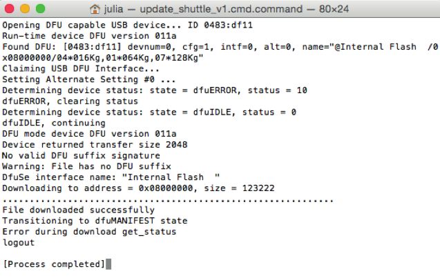
THE AIRPLANES
If you’re already familiar with the Airplanes (envelopes) in Endorphin.es TERMINAL module – you will find the same envelopes
in GRAND TERMINAL as well. Tested for years, with its unique no-time stretch algorithm when adjusting the shapes of the
slopes, they provide all necessary functions that an envelope may have in a modular setup.
Airplanes are transient function generators that generate control voltages after an incoming trigger/pulse. Each Airplane has
two phases: take off (a.k.a. attack, ascent, climb, rise, upward, up) and landing (a.k.a. release/decay, descent, dive, sink, fall,
downward, down), and features separate bi-polar (-5 ... +5 volts) and uni-polar (0 ... +8 volts) outputs (exits) as well as end of
current, Airplane’s stage trigger outputs (zero or +6 volts). The relative brightness of LEDs under each exit shows the current
amplitude and help to monitor the output voltage polarity: red when the voltage goes below 0 volts and green when the output
goes higher than 0 volts. At calm both Airplanes stay on hold waiting for an upcoming launch signal (at the check-in jack).
There are 3 different modes in which the Airplanes can fly:
Cruise mode (a.k.a. sustained, AR/ASR, on hold, long-haul flight) mode (trip selector in far right position) the Airplane takes off
to the highest level after receiving a triggergate (higher than approximately 0.65 volts constant signal) and stays in cruising
mode as long as the gate signal remains high. At any moment the gate signal drops, the Airplane performs the landing. During
landing the Airplane will immidiatly gain altitude (so called going-around or aborted landing) when a triggergate arrives.
Transient mode (a.k.a. AD, shorthaul flight) mode (trip selector in the middle position, the Airplane performs a take off after an
incoming trigger signal (may be short trigger or constant gate higher than 0.65 volts). Reaching the top of the ascent level, the
Airplane immediately performs a landing. Same as in Cruise mode, during a landing the Airplane will immidiatly gain altitude
after reciving a trigger or a gate signal.
Loop mode (a.k.a. cycling, nonstop flight, LFO) (trip selector in far left position) enables the Airplane to take off. Reaching the
top of the ascent level, the Airplane performs a landing. At the lowest descent stage the take off immediately begins and gains
altitude again and so on up to infinite. In this mode it will function as an LFO.
The End Of Stage outputs return short 1 ms triggers after take off or landing stages have been either fully ended or went into
cruising or in holding mode or were interrupted by the next stage after a trigger signal (the mode end of stage trigger is select-
able via jumpers for each stage and each Airplane separately on the backside of the Terminal – see the Jumperization Chart
later in this manual).

         lowest ascent level                                            top ascent level

   check-in

                                                                                                                                         time
                    Loop mode                              Transient mode                            Cruise mode

      End of Take-off phase trigger out                                                               End of Landing phase trigger out

                                          © 2013-2021 – Endorphin.es – International Airways                               page 3 of 18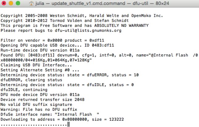
AT TAKE OFF & LANDING
The duration of take off and Landing stages are separately voltage controlleable and may be controlled manually with the ac-
cording knob or via incoming control voltage (the amount of CV is defined by using the knob as an attenuverter). When nothing
is plugged into the CV and key inputs, take off and Landing knobs vary the duration time of corresponding stage from 1 milli-
second to 10 seconds. When no control voltage plug is inserted into the appropriate CV IN jack, each attenuverting knob defines
bending of the according curve of the certain slope: either to exponential shape (knob is in far counterclockwise position), to
linear (knob is in centered position), or to logarithmic (knob position is far clockwise). These knobs have exponential char-
acteristic for turning them in both sides from the centerposition – i.e., the control changes slightly when the knob is close to
the middle position and more dramatically when the knob comes closer to its far left and right positions. Adjusting the linearity
doesn’t change the duration time of the according stage, as it’s usually expected in analog envelope generators (when feed-
back signal from the envelope’s output was routed into CV IN of a certain stage and at the same time playing with the polarity
and amplitude of that signal changed the shape but affected the duration of the stage). Altering the shape of the stage may
obtain continuosly variable responces that require precise shape, as for example ‘vactrol’ ones.
        LOG ascent            LIN ascent            LOG ascent           EXP ascent            LIN ascent
        EXP descent           LIN descent          LOG descent           EXP descent          LOG descent

                                                                                                                             time
                                            Slopes curves examples
The CV Input for each Airplane’s stage requires 3.5 mm mono plug (not stereo) to function properly. The range of acceptable-
voltage is ±5 volts (10 Vpp). It’s also possible to contol the shape of the slope (from exp-to-lin-to-log) instead of the time. By
installing appropriate jumper settings (see the Jumperization Chart) the control of the input voltage is changed from ‘control
over parameter time’ to ‘control over parameter shape’.
There is however one tiny change in how CV applixes for the time duration of each slope. Each black polarizer knob – when
turned from the middle into CW (+) direction – enlarges the duration of the appropriate stage (attack/decay) and – when
turned into CCW (-) direction – shortens the duration of that stage.
After different approaches, we consider that way of functionality to be more performance oriented, so musicians can always
be aware of what to expect from envelopes modulated by CV.

                                     © 2013-2021 – Endorphin.es – International Airways                              page 4 of 18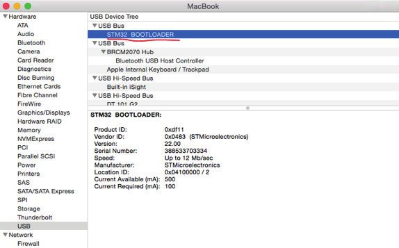
FILTER TYPES
Filters play an important role in shaping the tone of the timbre. This goes as far as sometimes a filter itself may define the
whole style of music. Filtering frequencies of waveforms gives one of the most drastic changes in sound one may obtain from
synthesizers, making the timbre either bright, dull, wooden or harsh.
It is always interesting to have a few different filters in the modular systems to gain a wider sound palette: Using them in the
way a sculptor would use different knifes while creating a statue or a photographer changing his lenses to get a special picture
Having a bunch of analogue filters always requires more space in the rack and more costs are the result. GRAND TERMINAL has
a powerful ARM M4 DSP inside that runs dual filters and a stereo effect processor at 16 bits and 48 kHz sampling rate.
FILTER CONTROLS
                                                  The audio input of filter A and filter B marked with ‘TO THE GATES’ – are AC
                                                  coupled audio inputs. The two ‘FOLLOW ME’ - MODE A and B buttons define the
                                                  type of filter applied. Pressing the buttons shortly cycles thru all 8 filter
                                                  types. Small A trim and B trim knobs define the input level of the appropriate
                                                  multi-filter/gate/channel. When one of the trimmer knobs is fully CCW, the
                                                  input of that filter accepts modular level of the signal – i.e. +/-5V (approx.
                                                  +15dBu) with some reserve for extra gain. Signals that exceed the range of
                                                  approx. +/-6.9V (approx. +19dBu) will be soft clipped (saturated) to avoid
                                                  clipping distortion. When one of the trimmer knobs is fully CW, the input gain
                                                  of the signal corresponds to an approximately 10 times higher source – i.e. a
                                                  normal 1Vpp (+/0.5V) line-level signal with some reserve for the headroom.
Keep in mind you can always decrease (attenuate) the incoming signal level for accepting up to 0 or +4dBu adjusting the ap-
propriate knobs when connecting professional audio electronics. You may also connect portable electronics directly (approx.
-10dBV level) that has a 3.5mm jack output (i.e. mp3-player or something similar) without the necessity to adjust the gain of
your mp3-player to a modular level.
                                            Moreover, input A is a STEREO input: If you insert a stereo 3.5mm plug there, the
                                            right channel (ring of the plug) can pass thru the switched connection of the jack B
                                            into the filter B (this also works with TRRS plugs). If you are using mono cables only,
                                            then each input of filters work independently without any pre-routed connections.
                                            A row of 4 LEDs between the X and Y knobs show the currently selected filter type. If
                                            a LED is fully lit, it corresponds to the lower row of icons (filter types 1-4) and if the
                                            LED is semi lit (or dimmed), it corresponds to the upper row of icons (filter types 5-8).
                                            The X and Y knobs and the corresponding DC-coupled CV inputs define X and Y pa-
                                            rameter changes of the filter chosen – only two parameters may be changed per
                                            each filter.
                                            X usually adjusts the cut-off frequency and
                                            Y adjusts the resonance. Sometimes Y is as-
                                            signed to alternative functions like length of
                                            the decay (#3 Vactrol filter) or bandwidth (#7
                                            Bandpass filter).
                                          The CV IN jacks accept UNIPOLAR 0 ... +5V CV in-
                                          put. Everything that is higher than +5V is being
                                          saturated. Those inputs are made to be fully
                                          compatible with the SHUTTLE CONTROL CV out-
                                          puts (unipolar type). Keep that in mind when
                                          applying other envelopes to the CV inputs, you
                                          may need to attenuate them (using an exter-
                                          nal attenuator module or the attenuators of the
GATEWAYT_XP). When no jack is inserted in the appropriate CV input, define the change of
that parameter by turning the corresponding knobs (X/Y). However when CV is applied,
the corresponding knob defines the amount of CV that is applied to that parameter.
Hint: If you urgently need a manual offset and CV attenuator/polarizer both simultaneously, we advise you to use one part of
the GATEWAYT_XP (as dual 1+1 mixer) – the red knob ‘Offset’ will give you an offset from 0 to 6.5V and the bi-polar attenuator will
accept any bi- or uni-polar voltage to a desired scale.

                                     © 2013-2021 – Endorphin.es – International Airways                                 page 5 of 18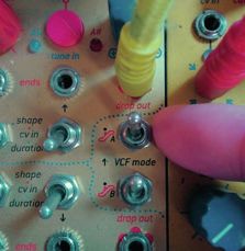
FILTER TYPES
                    There are two multi-filters/gates/channels marked ’TO THE GATES’: A and B. Each filter has 8 different
                    modes – so each can be one of the 8 filter types. This is a set of digital modelled filters with some added
                    non-linearities to recreate the approximate behaviour of some well-known and often used analogue volt-
                    age controlled filters.
                    Mention: Your choice of the filter type depends on the type of music you like to perform and – of course –
                    what fits best to your taste and needs.

1. TRANSISTOR LADDER FILTER            is a 24 db/oct low-pass filter, modelled after the famous Minimoog filter. It has a rich slope
   and deep bass sound. It self-oscillates at full resonance with the recognizable chickens peep timbre when being modulat-
   ed. Suites well for every kind of sound. Frequency response up to 16 kHz.
2. DIODE LADDER FILTER is a 18 db/oct low-pass filter, inspired by the Roland TB-303 and EMS Synthi A filters. It gives a
   distinct ‘acid’ feel and suites very well for all that techno arpeggios, bass sounds etc. Frequency response up to18 kHz.
3. VACTROL LO-PASS GATE is a 12 db/oct modelled after Buchla's LPG and was used in it’s traditional way (with an analogue
   Vactrol) in the Endorphin.es TERMINAL a few years earlier. That filter type simulates non-resonant vactrol filter models,
   however instead of the resonance, we can control the DECAY time (closing resistance) of the vactrol. We all know, there
   are different types of vactrols – ones are fast, other are slow. Slow ones – when ‘pinging’ them with a short pulse of CV –
   give that distinct ‘Buchla Bongo’ sound (passing a small 1ms trigger immediately opens the gate but the gate itself will be
   closed much slower giving a so called musical natural response). Adjusting the Y control of that filter, adjusts the decay –
   from short decays around 120 ms (full CCW) to long ones with up to 4 seconds duration (far CW). Frequency response up
   to 17 kHz. Trivia: The Vactrol Lo-Pass Gate simulates the behaviour of an opto-coupler (called ‘Vactrol’) in a Sallen-Key filter
   topology. Applied CV (or manual offset) lights up the LED and the LED with its light affects the coupled photo-resistor. The
   photo-resistor changes its resistance and as a result, the filter cuts more or less frequencies.
4. RESONANT VACTROL LO-PASS GATE              is a variation of the previously decribes vactrol filter model, however instead of
   adjusting the decay time, we now control the resonance. The decay is fixed in this filter type and is set to approximately the
   response of the mostly used standard (fast) vactrols. So we don’t lose dynamic, but still have a distinct lo-pass sound. The
   resonance of the sound is ringing, just as it may be expected from a normal lo-pass gate. Frequency response up to 17 kHz.
5. STATE VARIABLE LOW-PASS FILTER          is a 12 db/oct filter. Unlike ladder or diode filter types, its sound is probably less
   harmonically rich, however is provides a cleaner sound because of a flatter cut-off slope. That type of filter was used first in
   Oberheim SEM, Korg MS-10/20 and many more other synthesizers. That filter also features a resonance loudness compen-
   sation, because usually with more resonance the amplitude decreases. Frequency response up to 16 kHz.
6. STATE VARIABLE HIGH-PASS FILTER        – same as the previous state-variable filter, but this one passes the high frequencies
   and filters the lower ones. Be aware: At minimal resonance (Y) and full open cut-off (X) it cuts the low frequencies up to a
   full silence.
7. STATE VARIABLE BAND-PASS FILTER – same as the other state-variable filters (5 & 6), but passes only a defined band
   of frequencies. X defines the band’s centre point and Y defines the width of the band. It doesn’t have a resonance control
   since the band is always on one level. Keep in mind: The amplitude of the resulting waveform changes within altering the
   band width.
8. COMB FILTER It recreates a series of harmonically related amounts of notch filters. In static state, it sounds similar to a
   phaser, but with modulation applied to the frequency it comes closer to a flanger. With resonance set to full CW it becomes
   a resonator.

                                      © 2013-2021 – Endorphin.es – International Airways                               page 6 of 18
MODES/SECONDARY FUNCTIONS
To change the mode of the GRAND TERMINAL or to alter settings of a parameter, which is set up as a secondary function of a
knob or CV input, there are a few button combinations to press. While pressing these button combinations you will see the
‘Follow me’ LED will blink red when enabling and green when disabling that secondary function. When you change to another
mode the LED constantly shows another colour (off/green/red).
FILTER VOLUME/PANNING ADJUSTMENT
After holding the MODE (‘Follow me’) button of a multi-filter/channel/gate for a longer than 1 second, you get access to the
secondary functions for that multi-filter/channel/gate.
In this case think of the
secondary function lay-
out as a mixer, where the
lower row of knobs de-
fines the volume and the
next upper row defines
the panning.
The X parameter defines
a pan – this means –
how the multi-filter/gate/
channel is positioned in
the stereo panorama. Ad-
justing the X knob to 12
o’clock, will spread equal
power of the multi-filter/
gate output (amplitude)
into the left and right
channel of the final output of the GRAND TERMINAL. Keep in mind, that when you use the MONO (modular level) output – ad-
justing the panning will not be audible, since both L/R outputs are always with the same power. You will see the LEDs under
the appropriate channel moving left and right when adjusting the panning and after 2 seconds, the LEDs return back to work
as a VU-meter showing the volume level of the channel.
The Y knob defines a volume of the multi-filter’s/channel’s/gate’s output. If you crank it more than approximately 70% of the
knobs range (after approximately 2 o’clock), you will experience an extra increase in gain up to a certain level of distortion at
the input of the filter. This is useful when you want to play distorted acid lines without using a distortion module or a guitar
pedal in addition to your modular setup. Attention: Adding extra distortion considerably adds aliasing and therefore some gain
into the output of your filter.
Hint: After the Y knob crosses the level from normal volume to the approx. 2 o’clock position, the further rotation will cause
distortion of that channel’s volume. At the moment of crossing over 100% of the normal volume level, you will see the FOLLOW
ME LED blinking shortly in RED. When you decrease the level of distortion to a normal 100% volume level, you may notice the
LED blinking shortly in GREEN (‘back to normal’ and channel is not overdriven/clipped anymore).
You may visually monitor the level of the signal by watching the 4 LEDs of each multi-filter/gate/channel that work as a VU-me-
ter in that mode.
KNOB SNAP
Important: After you adjusted the filter’s cut-off manually or attenuate incoming CV for a certain parameter, you may want to
access the secondary option for that channel. Holding a MODE button for a while (over one second) gives you the access to the
volume and panning via manual X and Y knobs. However while accessing into that mode, the amounts of manual offset or CV
attenuation (set by the knobs) are stored while the CV continues to modulate a certain parameter of the filter. When you return
to the primary mode (by pressing the same MODE button again for more than a second), the values of X/Y are still as stored
before, at the time you decided to go alter the secondary function. BUT the position of the knob will – in most cases – NOT rep-
resent the actual value stored! Now when you change to a new value by moving the knob, there will be no instant jump, but a
mixture of a jump, a snap and relative behaviour (you may know these options from other synthesizers which have more than
one function assigned to one knob). Same applies to the Cabin pressure section as well.

                                     © 2013-2021 – Endorphin.es – International Airways                             page 7 of 18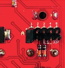
FILTER ROUTING
There are three different modes how the filters/gates/channels may be routed to the final stereo out. By pressing the two
MODE buttons simultaneously for approx. 1 second, it will change the filter’s routing.

1. PARAL.LEL (standard: dual mode): Filters A and B are independent and both are summed together at the output with FX
   applied to the mix. In that mode the ‘Follow me’ LED is off. Press the TYPE button for a moment to bypass the Cabin Pres-
   sure processor for Gate A, so you may use Gate B with effects applied while Gate A will always be fully dry (Basslines often
   seem muddy with reverb).
2. STEREO mode: Filter A and B are linked together. The X/Y knobs and the MODE button of filter B are inactive and the X/Y knobs
   of filter A control filter A and B at the same time. Both filters share the same filter type and by default are put in spread pan
   (filter A far left and filter B far right – altering the panning under secondary function from L to R shifts the panning vice-ver-
   sa for both channels). In that mode the ‘Follow me’ LED shines RED. Pressing the TYPE button for a moment in that mode
   immediately spreads Gate A to the far left and Gate B to far right in the panorama no matter which panning was set before.
3. SERIAL mode: The audio inputs of Gate A and B are summed together and pass into filter A first, and then into filter B. Press-
   ing the TYPE button for a moment in that mode swaps the filter types selected for A and B with one another (you will notice
   that by watching the LEDs).
CABIN PRESSURE EFFECT PROCESSOR
There are 8 effect types which recreate different ambient spaces and they are more or less arranged in a size-wise order –
going from bigger spaces (like halls) to smaller ones, finishing with a chorus (very short ambiences). Again as with the filter
types, the choice of the effect is entirely based on your musical taste. The effects we picked suit a wide pallet of musician’s
needs: from small rooms for Techno up to infinite spaces of experimental Avant-garde drones, but who says one cannot use a
hall in Techno.
The effect selection is done by pressing the TYPE button in the cabin pressure area on upper left corner of the GRAND TERMI-
NAL. The effects are cycled one by one. Some effects work in true stereo or widen the stereo spread that may be merely audible
to hear from the mono output.

The current effect type chosen is shown at the row of LEDs between the X and Y knobs by shortly blinking of the LED. Only one
effect may be chosen at a time. The 8 LEDs correspond to the 8 effect preset cells. The Cabin pressure knob always defines the
DRY/WET parameter of the effect: When the knob is fully CCW, then there is no effect at all (dry output only). When the knob is
fully CW, then the the signal will be totally processed with the effect (100% wet). Adjusting that knob is a balance of how the
sound is processed: Think of it as you open the window to get some fresh air – you may open it only a bit for a small ventilation
or fully open it to get lots of fresh air. The corresponding CV IN jack is a CV control for the dry/wet parameter. It accepts BI-POLAR
-5v ... +5v voltage and when the plug with CV is inserted (3.5mm MONO jack), the CABIN CRESSURE knob acts as an attenuator
for that incoming CV.
Each effect has a few additional parameters. These parameters are defined by the CABIN FEVER knob (to be found in the CABIN
FEVER area on the upper right side of the GRAND TERMINAL), corresponding to the CV IN jack and a TAP button. Depending on
the effect, these controls are assigned to different parameters as described below. Pressing and holding the TAP button longer
than 1 second activates the secondary mode for the CABIN FEVER knob. The ‘Follow me’ LED will blink RED once, so you will
notice you are in secondary mode. You can also check if the corresponding effect slot’s LED (between X and Y) will strobe
TWICE instead of once per a few seconds, to see in which mode you are (blinking twice > secondary parameter, blinking once >
primary parameter). Press and hold the TAP again for around 1 second and you will notice the ‘Follow me’ LED will blink GREEN
once and the corresponding effect slot’s LED will strobe ONCE instead of twice per a few seconds meaning you are back in
primary mode.

                                      © 2013-2021 – Endorphin.es – International Airways                                page 8 of 18
These are the effects (find detailed information in the FX Addendum at the end of the manual):
AIRWAYS BANK DARKWAVES BANK
•••• •••• HALL REVERB: ‘Cabin fever’ knob defines the •••• •••• GATED REVERB is based around plate reverb with
decay of the reverb or hall size. Holding ‘tap’ for noise gate. The primary ‘cabin fever’ defines the
longer than 1 second enables the secondary reverb decay, but the secondary defines the
function for ‘cabin fever’: fixed hi-pass-filter to cut threshold of the noise gate. Noise gate’s attack
off low frequencies and have more ‘air’ in the final and decay are fixed and chosen experimentally to
output. fit most musical styles.
••••• •••• SHIMMER REVERB is a variation of the hall reverb ••••• •••• SPRING REVERB: The primary ‘cabin fever’ defines
with a pitch shifter to create choir-like, huge and the decay of the reverb. With the ‘tap’ button you
unrealistic spaces. The primary ‘cabin fever’ can simulate a sound as if you pluck the real
function defines the decay and the secondary spring with your finger. The secondary function is
function defines the amount of pitch-shifter tied to the ‘tap’ button’s ‘pluck the spring’ feature
mixed into original reverb. and defines the DECAY of how fast the spring will
calm down after manually plucking it.
••••• •••• STEREO ROOM REVERB recreates a sort of stereo
room ambience. Primary ‘cabin fever’ parameter ••••• •••• REVERSED REVERB takes the reverb tail of the
defines room size and the secondary defines the sound and reverses it. If applied on a drums like
stereo spread of the reverb, from mono up to a snare then it creates breathing effect. ‘Cabin
huge stereo spread. pressure’ knob defines the predelay time along as
acts as a dry/wet control. 'Cabin fever' sets the
••••• •••• PLATE REVERB: The primary ‘cabin fever’ defines reverb decay value. Holding ‘tap’ for longer than
the decay of the reverb. In real life equivalent this 1 second enables the secondary function for
is the distance from the pickups to the metal plate ‘cabin fever’: damping, i.e. volume of the tail (in
which is how long the tail of the reverb ispresent. our case tail = 'head' as the tail is reversed).
Secondary parameter defines the amount of
pre-delay to distant sounds in ambience. ••••• •••• FLANGER: The ‘cabin pressure’ knob sets the
amount of delay. With primary ‘cabin fever’ we set
•••• •••• SPRING REVERB: The primary ‘cabin fever’ defines the LFO speed. The secondary defines the
the decay of the reverb. With the ‘tap’ button you feedback. Playing with that three parameters
can simulate a sound as if you pluck the real allows to achieve sweeping, airplane engine alike
spring with your finger. The secondary function is sound with a pretty wide range.
tied to the ‘tap’ button’s ‘pluck the spring’ feature
and defines the decay of how fast the spring will •••• •••• RING MODULATOR multiplies the signal with an
calm down after manually plucking it. internal sine wave oscillator. ‘Cabin pressure’
defines the amount of modulation and ‘cabin
•••• ••••• PING-PONG DELAY is a stereo clocked delay. A ‘tap’ fever’ defines the speed of the oscillator. Secret
is usually three or more short clicks on the ‘tap’ ingredient – feedback! Its amount is controlled by
button. The primary ‘cabin fever’ parameter the secondary ‘cabin fever’ and brings special
defines the feedback of the delay or repeats. dirtiness to the sounds.
The secondary defines the clock division of the
incoming tap/clock: 1, 3/4, 2/3, 1/2, 1/3, 1/4, 1/8 •••• ••••• OVERDRIVE: ‘Cabin pressure’ knob adjusts the
drive amount with volume compensation, while
•••• ••••• TAPE ECHO is a delay with 3 fixed playback heads. ‘cabin fever’ defines the tone control as usually
Primary ‘cabin fever’ parameter defines the d elay found in guitar pedals. The ‘tap’ button makes the
repeat rate which is the speed of tape. The ‘tap’ effect active or bypassed, like the switch on a
button works in a limited frequency range o f guitar pedal – and so does ‘cabin fever’ latching
manual tapping and defines the amount of trigger CV input.
feedback. The secondary works as a divider for
the incoming clock. •••• ••••• PEAK COMPRESSOR: ‘Cabin pressure’ knob defines
the threshold from -90dB to 0dB (fully CW).
•••• ••••• CHORUS: Primary ‘cabin fever’ knob defines the Primary ‘cabin fever’ sets the amount of gain
feedback amount. In average amounts, it creates reduction (ratio) from 1 to 25. Secondary
typical unison effect however in full CW it goes to parameter defines the attack, from 1 to
an infinite feedback resulting unrealistic ambient. 200 msec. Release is always ‘auto’. ‘C. fever’ CV
Secondary parameter defines the modulation input is an unattenuated side-chain input.
depth, which is ‘full on’ by default.
•••• ••••• FREEZER/LOOPER: When ‘tap’ is pressed (or ‘cabin
fever’ CV gate is ON), the audio is looped by the
grain length defined by the ‘cabin fever’ knob –
and with the speed – defined by ‘cabin pressure’
knob or CV – applied.
© 2013-2021 – Endorphin.es – International Airways page 9 of 18JUMPERIZATION ADDENDUM CHART
The GRAND TERMINAL is a small yet complex module which every user can customise it to his own needs.
Doepfer A-100 bus IDC-connector. We advise that you use the supplied 16-pin ribbon cable! Please ensure that the red stripe
of the cable (the side with the top pair of pins/wires) is connected to the negative -12V rail when plugging the cable into your
power distribution board. If the ribbon cable is connected backwards, you could damage the module. Please check twice before
you make the connection and turn on your modular since failure/malfunction due to a wrongly connected module (“magic
smoke”) is not covered by our warranty.
Each Airplane has a10-pin expansion slot where jumpers are installed: All of the pins are able to either carry jumpers or to
connect an expansion module. The expansion module will be help you to a conveniently use both Airplanes as VCOs as well
as all the switched functions described below. The jumpers must be installed vertically, separately for each pair of 1-5 pins to
customize the functions below:
• when jumper (1) (most left one, marked with a bold white line nearby) is installed it will enable full 12db/oct VCF mode
on the according A or B gate. When enabling the VCF mode on the gate A, it is possible for example, to use this gate for CV
processing as a voltage controlled slew limiter (portamento) for controlling the pitch of a VCO.
• when jumper (2) is installed, the Airplane will output a short 1ms trigger after the end of each take off (attack) stage.
• when jumper (3) is installed, the Airplane will output a short 1ms trigger after end of each landing (decay/release) stage at
the end of stageoutputs. Jumpers(2) and (3) can be installed simultaneously giving you a trigger when a stage has end-
ed at the end of stage outputs. When Combining the end of stage triggers, one may obtain additional functions such as
2x or ½ clock multipying or even more when chaining both Airplanes together.
• when jumper (4) is installed, the control voltage at CV input of take off stage will control the shape of the slope instead
of its time. The attenuverter will polarize the accepted incoming voltages of maximum ±5 volts into positive (knob in far
clock-wise position) or negative (inverted, knob at far counter-clockwise position) amount of the control voltage applied.
For example, when a current of +5 volts is applied into the CV input when the attenuverting knob is far clockwise, this
will result in a LOG (logarithmic) curve and turns into an EXP (exponential) when the attenuverting knob will be in the far
counter-clockwise position.
• when jumper (5) is installed, the control voltage at the CV input of the landing stage will control the shape of the slope
instead of its time. Thus when using (4) and (5) jumpers you won’t be able to control the time of the slope via CV separate-
ly anymore but can only manualy change it with the according knobs or via the key in 1v/oct input when controlling both
stages at the same time.
© 2013-2021 – Endorphin.es – International Airways page 10 of 18As it was noticed above, all the A/B XPansion jumpers (row of 5 pairs of pins on the left and right side of the module’s backside)
correspond to the same functions as in the Endorphin.es Terminal.
Jumper pairs #2 and #3 (when installed, yellow by default) define the end of attack and end of decay triggers are enabled.
Jumper pairs #4 and #5 enable CV control over the shape of envelope’s attack and decay instead of the time stretch. Jumper
pair #1 (green by default) defines the VCF/VCFA mode. Same as in the Endorphin.es TERMINAL, when this jumper is installed,
then the appropriate Gate works in pure VCF mode. However when you remove the jumper (or switch down the appropriate
VCF Mode toggle at the GatewayT_XP), then each filter will have the alternative (experimental) VCFA mode – while cutting the
frequencies, the amplitude of the signal will decrease as well.
That’s a tribute to the original Buchla Lo-Pass Gate (LPG) functionality (VCFA/both modes) spread on other filter types, howev-
er may be not always suitable, as there may be stronger volume drops at cut-off modulation.
TIPP: At the same time, in that VCFA mode, such filters as bandpass or comb close fully when the cut-off knob is set full CCW,
so you may use them in a creative way.
© 2013-2021 – Endorphin.es – International Airways page 11 of 18FIRMWARE UPDATE ADDENDUM
Endorphin.es continuously works on new features and improvements as well as on bug fixes. It is recommended to use the
latest firmware installed to experience the latest features. It is also possible to downgrade to any earlier or custom firmwares
in case you like them better.
Warning – during update procedure you will lose your filters/effects tweakings stored in the memory.
FIRMWARE HISTORY:
Grand Terminal v. 1.6—major update (latest edits 26.02.2017):
http://firmware.endorphin.es/Grand_Terminal_v1.6_MAC_OSX_update.zip
What's new in v.1.6
• CV sampling frequency for X and Y jacks increased twice.
• Filter #1 (transistor ladder)—improved resonance volume drop.
• Filter #3 (vactrol)—shorted the shortest vactrol's decay time.
• Filter #4 (vactrol with resonance)—improved resonance behaviour.
• Filter #6 (svf high pass)—removed bleed when resonance is applied on (bleed may still occur at high distortion gain).
• Exponential curve of Cabin pressure knob.
• All updates after current version 1.6 may also be done via audio file playback into Gate A input (QPSK modulation):
a) Pressing TAP during power-up enables audio firmware update into
Gate A audio input (re-power to boot in normal mode again). Mono file,
1.5 minutes, line level (adjusted with Gate A input trimmer).
b) Pressing TYPE during power up—the module will be loaded as before
in normal DFU mode (update via USB).
• Effect #4 (plate reverb) – high pass filter is fixed to a moderate level to
prevent boomy lo-frequencies. Secondary Cabin fever parameter now
controls pre-delay amount (before pre-delay was set to zero, now it can
enhance the room size).
HINT: See next page for further news in update 1.6!
© 2013-2021 – Endorphin.es – International Airways page 12 of 18• VCF/VCFA mode revised:
a) when the 1st green jumper on the XP pins on
the backside of each Gate is ON (VCF mode
switch on Gateway is UP), then the certain
Gate works as pure VCF.
b) when NO 1st jumper is installed (VCF mode
switch on Gateway is DOWN), then:
• Y knob (usually resonance) is no more CV
controlled (only manual change).
• instead, Y jack in that mode becomes a CV
control over a VCA at certain Gate. Maximal
range of CV control over VCA is defined by
Y knob in secondary gate mode (including
extra gain for distortion!). That mode is
useful when having CV control over gain to
create accents.
Grand Terminal v.1.5 – 291216 – minor bug fixes
http://firmware.endorphin.es/Grand_Terminal_v1.5_MAC_OSX_update.zip
• #1, #5, #6 filter's ranges adjusted, filters close fully
• State Variable Filters #5–#7 glitches in low/high ranges removed
• improved filter volumes at VCFA mode (1st jumper – green by default – NOT installed for certain Gate – see Jumperization
Addendum) and tuned to each filter without volume drop. Now #7 Bandpass and #8 Comb Filter close to full silence in
VCFA mode.
• improved resonance amount, glitches removed in #4 Resonant Vactrol Lo-Pass Gate (sometimes caused module's full mute)
• effect #7 (Tape Echo) Cabin Fever control inverted (faster tape speed > longer delay time)
• logarithmic feeling for all resonance (Y) parameters as well as cabin fever knob behavior in effect #5 (Spring Reverb)
• improved logarithmic view of VU meter in secondary filter modes for more dynamic signal monitoring
• Silent Reset of the module (press all 4 buttons at once for more than 3 seconds)
• Serial Mode improved: Gate A and B inputs are summing inputs into the filter A and then into filter B. Long hold on the 'type'
button swaps filter A and B types with one another.
• Stereo Mode improved: long hold on the 'type' button immediately spreads Gate A left and Gate B right in the panning, no
matter what panning was set for each gate earlier.
Grand Terminal v.1.4 – 251116 – release candidate
http://firmware.endorphin.es/Grand_Terminal_v1.4_MAC_OSX_update.zip
© 2013-2021 – Endorphin.es – International Airways page 13 of 18FILTER/FX SCANNING ADDENDUM
You may wonder, however all the time you tweak the knobs of every filter or effect, all last changed values and knob posi-
tions are stored in the memory.
FILTER SCANNING MODE
By pressing the TYPE + MODE A or TAP + MODE B buttons
simultaneously for longer than 1 second, you will en-
able switching/scanning through the filter types under
incoming CV—is called the FILTER SCANNING MODE. This
works for filter A or B separately, so the values set for
each filter are stored and then immediately recalled un-
der upcoming CV for a certain filter type. The idea is, that
by the scanning the filters you obtain glitchy, Aphex-
Twin alike sound sequences.
In that mode, the behaviour of the X and Y parameters
is different.
The range of 0...+5V is divided into 8 zones (with ad-
justed hysteresis to eliminate spontaneous switch at
small voltage fluctuation) with approx. 0.625V increase
per step. So far, if the incoming CV is from 0V to approxi-
mately 0.625V, then the first filter type is chosen. If the
CV is in the range from 0.625 to 1.25V, then the second
filter is chosen and so on—up to the 8th filter. That’s true
when the offset knob(X) is set to zero (fully CCW).
By adjusting the offset and attenuation of incoming
scanning CV with the Y knob/jack, you may scan a cer-
tain range of filters.
IMPORTANT: Because the DSP in the module can only
handle to load two filters and one effect at once, fast
audio-rate scanning of the filters and effects may cause clicks. There are small crossfades in volume between the transitions
and we tried to adjust fade regions as possible to minimize them, still they cannot be fully eliminated.
CABIN PRESSURE SCAN
By pressing and holding the TYPE + TAP buttons simultaneously for longer than 1 second, it enables to switch inbetween the
effect types under incoming CV. It is very similar to the filter scanning, however with some differences.
Every effect type has a memory, so the values of every parameter are stored and then immediately recalled under incoming
CV for a certain effect type. The CV input for Cabin Pressure accepts bi-polar -5...+5V CV signal and changes the type of effect
under incoming CV. The range of -5...+5V is divided into 8 zones (with adjusted hysteresis range) with approx. 1.25V per step.
So far, if the incoming CV is from -5V to -3.75V, then the first effect type is chosen. If the CV is in the range from -3.75 to -2.5V,
then the second effect is chosen and so on, up to the 8th effect. In that mode, the CABIN PRESSURE parameter is no longer CV
controlled and only works as a manual DRY/WET control. The CABIN FEVER knob/buton/jack are functioning as they were
before.
© 2013-2021 – Endorphin.es – International Airways page 14 of 18UPDATE PROCEDURE UNDER MAC OS X. (You find the update under windows a few pages further)
1. Download and unpack and following archive into one folder:
http://firmware.endorphin.es/Grand_Terminal_v1.5_MAC_OSX_update.zip
2. Turn off your Grand Terminal (or even better the entire modular rack). Connect your GRAND TER-
MINAL module to your MAC with a micro USB cable by plugging it into the micro USB connector
located on the right side of the GT PCB. The micro USB cable is not included with the package
so you have to find one on your own – e.g. from your Android phone charger. The easiest way to
connect the module for the update procedure is to not unmount the module of your rack – but
to remove some modules from your case right to the GT. Like this you have an easy access to
the micro USB connector. Otherwise, when the GT is not mounted in the rack, it is recommended
to stand it up – e.g. you may put a small screwdriver in one of its lower mounting holes as a
stand and put it upright on the table.
3. Check that first pair of jumpers at XP_A is installed (full VCF mode for Gate A enabled) or toggle
appropriate switch on the GATEWAYT_XP up (in case the GW is connected to GT:
4. Power-up the your GRAND TERMINAL (or modular system in which it is mounted) while holding the TYPE button (the one
right from the Cabin Pressure knob) on the GT module. Hold the button up to 5-7 seconds after you turned the power on and
then release it. Grand Terminal should now be set into the DFU (Direct Firmware Update) mode – none of 8 LEDs showing
the filter/effect type chosen should light up, however MAC OS X should detect new plug-n-play generic USB device, which
will appear in your Hardware > USB list as STM32 BOOTLOADER: Applications > Utilities > System Information:
5. After you ensured the STM32 BOOTLOADER is present in your hardware list, navigate to the ‘Grand_Terminal_MAC_OSX_up-
date’ folder you unpacked before.
6. To load the new firmware on your Grand Terminal – simply double click on the following command file:
Grand_Terminal_MAC_OSX_update\update_GT_v1.2.cmd.command
If after clicking the command you receive the message that you are not allowed to launch third party apps on your MAC,
simply follow these instructions to bypass this behavior: CLICK HERE
© 2013-2021 – Endorphin.es – International Airways page 15 of 18Then launch the command again and confirm.
7. The OSX’s Terminal window will open showing the update process:
8. After roundabout 10 seconds, the process will be finished. Don’t interrupt it – just take a few deep breaths.
9. Once the process is completed, the Grand Terminal will reboot with the new firmware and you will see the row of 8 LEDs will
light up with 1st and 5th LEDs up (first filter type chosen at every Gate with the first LEDs strobing. If not – simply remove
the micro-USB cable, turn the modular system power off and on again.
Note: You may have ‘Error during download get_status’ message at the end of the upgrade procedure. This is normal. Just close
the OSX Terminal.APP window when you’re done.
© 2013-2021 – Endorphin.es – International Airways page 16 of 18UPDATE PROCEDURE UNDER WINDOWS via USB for firmware v1.6 or earlier
1. Download and install free DfuSe USB device firmware upgrade STMicroelectronics extension (STSW-STM32080) from the
official STMicroelectronics web-site:
http://www.st.com/web/en/catalog/tools/FM147/CL1794/SC961/SS1533/PF257916
The current version is 3.0.3 (3.0.5). No SMS or registration is required to download the installer. It is recommended to
have Windows XP/7/8.1 or a later version of operating system.
2. Download the latest Grand Terminal firmware update DFU file:
http://firmware.endorphin.es/Grand_Terminal_v1.6_MAC_OSX_update.zip
3. Turn off your Grand Terminal (or better entire modular rack from which GT is powered). Connect
your Grand Terminal module to your PC with micro USB cable and micro USB connector located
on the right side of the GT. Micro USB cable is not included with the package so you have to
find one on your own – e.g. from your Android phone charger. The easiest way to do that do not
plugging the module out of your rack – is to remove some modules from your case that stand
right from the GT to have an easy access to micro USB connector. Otherwise, when GT is not in
the rack, it is recommended to stand it up – e.g. you may put the screwdriver in one of its lower
mounting holes and put it on the table.
4. Check that first pair of jumpers at XP_A is installed (full VCF mode for Gate A enabled) or toggle
appropriate switch on the GatewayT_XP up (in case GW is connected to GT):
5. Power-up again your Grand Terminal (or modular system where it is powered) while holding TYPE button on the GT module
(the one right from the Cabin Pressure knob). Hold the button up to 2 seconds after you turned on the power on and then
release it. Grand Terminal should be loaded into DFU (Direct Firmware Update) mode – no one of 8 LEDs showing the filter/
effect type chosen shouldn’t light up, however Windows should detect new plug-n-play generic USB device which will be
appear in your Windows Devices list (STM32 Device in DFU Mode / STM32 BOOTLOADER). Wait for a while until Windows
installs driver for it – the usual procedure just like you insert ordinary USB-flash drive first time in your computer. Don’t be
afraid to see Grand Terminal being in DFU mode – any time you can exit it by turning its power off and on again.
© 2013-2021 – Endorphin.es – International Airways page 17 of 186. After Windows successfully installs drivers for new devices (they should be installed automatically after you installed
DfuSe software) you may go to: Start > All Programs > STMictoelectornics > DfuSe > DfuSe Demonstration. You will see
STM Device in DFU Mode in the available DFU Devices list:
If your Grand Terminal still does not appear in the available DFU devices list, go to Control panel > Device Manager and find
there STM32BOOTLOADER device marked with ‘!’ sign. That means drivers were not automatically installed for it. Simply
double click on that device and press Update driver > Choose manually and choose the folder where you have in-
stalled DfuSe before (usually it is located at C:\Program Files (x86)\STMicroelectronics\Software\DfuSe v3.0.5\).
Afterwards the driver will be installed and you may repeat that step 5) again.
7. After your Grand Terminal appeared in available DFU devices list, press Choose... from Upgrade or Verify Action part of
the window and after the new window will open – choose new firmware file (DFU) you’ve downloaded (see the links with
firmware above).
8. Afterwards press Upgrade and wait until the operation will be finished (usually up to 10 seconds). Before updating you
have to confirm that firmware file is correct for that device. Don’t disconnect or turn off the Grand Terminal during that
procedure!
9. After upgrade operation is finished you will see successful green upgrade message in the bottom of DfuSe window: You
may now quit DfuSe Demo and turn your Grand Terminal power off and on again. If it’s powered with own PSU – just turn the
switch off and on.
10. Enjoy new the features.
© 2013-2021 – Endorphin.es – International Airways page 18 of 18STARS CAN'T SHINE WITHOUT THE DARKNESS
CABIN PRESSURE EFFECT PROCESSOR hosts 16 effects organiszed in two banks of 8.
The first effect bank is known as ‘AIRWAYS' and contains effects tailored for tonal content. It recreates different ambient spac-
es. The effects are approximately arranged by size – going from bigger spaces (like halls) to smaller ones finishing with delays
and chorus
The second bank 'DARKWAVES' contains 8 effects suitable for percussive sounds and serves a variety of different flavours.
See https://airways.endorphin.es for more details and latest updates.
INDICATOR (Queen of Pentacles, Blck_Noir, Grand Terminal, Milky Way) AIRWAYS (ambient effect bank) DARKWAVES (drum effect bank)
1 • (QoP) • (BN) •••• •••• (GT) •• •• (MW) HALL REVERB GATED REVERB
2 •• (QoP) •• (BN) ••••• •••• (GT) ••• •• (MW) SHIMMER REVERB SPRING REVERB
3 ••• (QoP) ••• (BN) ••••• •••• (GT) •• •• (MW) ROOM REVERB REVERSED REVERB
4 •••• (QoP) •••• (BN) ••••• •••• (GT) •• ••• (MW) PLATE REVERB FLANGER
5 • (QoP) • (BN) •••• •••• (GT) •• •• (MW) SPRING REVERB RING MODULATOR
6 •• (QoP) •• (BN) •••• ••••• (GT) ••• •• (MW) PING-PONG DELAY OVERDRIVE
7 ••• (QoP) ••• (BN) •••• ••••• (GT) •• •• (MW) TAPE ECHO DELAY COMPRESSOR
8 •••• (QoP) •••• (BN) •••• ••••• (GT) •• ••• (MW) CHORUS FREEZER
SPECIFIC FOR GRAND TERMINAL/MILKY WAY
The current effect type chosen is shown at the row of LEDs by shortly blinking of the LED. Only one
effect may be chosen at a time. The 8 LEDs of Grand Terminal correspond to the 8 effect preset cells.
Milky Way uses 4 LEDs that shine either half or fully lit to indicate the chosen effect.
SPECIFIC FOR BLCK_NOIR AND QUEEN OF PENTACLES
IMPORTANT: holding the TYPE button for longer than
1 second will enable effects on all drum voices no Cabin pressure adjusts the dry (fully CCW) and wet (fully CW)
matter if they were enabled or disabled from the ef- level or the effect applied to the drum voices where effect
switches were enabled (toggled to the right)
fect. Another long hold press will revert the effect
only to those drums that have their switches enabled. CV input range: -5...+5V (bipolar!) and Cabin pressure knob
works as attenuator when CV in applied
The effect type is selected by pressing the TYPE but- Long hold TYPE button enables effects on all drums (incl. AUX IN),
ton in the CABIN PRESSURE area on the upper right no matter if the drums were enabled to effect or not. Second long
corner of the module. The effects are cycled one by hold disables that feature
one (from 1st to 8th and then back to 1st and so on). We choose the effect type by short pressing TYPE button.
When powering the module as well as when select- Effects are cycled from 1 to 8 and then return back to 1 and so on
ing an effect the 'HAL9000' LED blinks certain times Effect indication: during effect select: HAL 9000 LED blinks:
(1-4) in green or red, identifying the effect currently • effect number 1, •• n°2, ••• n°3, •••• n°4
• effect number 5, •• n°6, ••• n°7,•••• n°8
selected. If the first effect is selected, then it blinks
green • once. Second effect: green •• twice. Third ef-
fect: green ••• trice and four times green •••• for effect #4.
At effect #5 it blinks red • once. Twice red •• for effect #6, trice red ••• for effect #7 and four times red •••• when effect #8
is chosen.
© 2010-2021 – Endorphin.es®SPECIFIC FOR BLCK_NOIR, QUEEN OF PENTACLES AND GRAND TERMINAL
ALTERNATIVE EFFECTS ENABLE MODE: by default, all audio that goes into AUX IN input isn’t affected by effect processor. Long
hold (1 second) of TYPE button enables effects on all drums including AUX IN, however pressing again for 1 second disables
that function.
BLCK_NOIR & QUEEN OF PENTACLES: By holding the TAP button (for more than 5 seconds), the alternative effects selection
mode is chosen: each of the five drum voice groups can be separately routed into the effect processor by turning their toggle
switches to the LEFT position. In that mode AUX Input is affected by effect processor. Selected mode is saved in the memory
and selected on next module’s power up.
In case of the GRAND TERMINAL, holding the TAP button for 5 seconds switches the channel, on which the effects can be by-
passed (by holding TYPE for 1 second). Normally "Gate A" is bypassing the effects. After holding TAP for 5 seconds "Gate B" will
have bypassed effects instead (in case you have the bypass activated).
IN GENERAL
Some effects work in true stereo, and some widen the stereo spread (which would not be audible in the mono output). Only one
effect can be chosen at a time. The CABIN PRESSURE knob always defines the DRY/WET parameter of the effect. When the knob
is fully CCW, then there is no effect at all: dry output only. When the knob is fully CW, then the signal will be fully processed with
the effect: 100% wet. Adjusting that knob is a balance of how the sound is processed: think of it as opening the window to get
some fresh air – you may open it only a bit for some ventilation, or fully open it to get lots of fresh air. The corresponding CV IN
jack is a CV control for the dry/wet parameter. It accepts BI-POLAR -5v...+5v voltage and when the plug with CV is inserted
(3.5mm MONO jack), the CABIN PRESSURE knob acts as an attenuator for that incoming CV.
Each effect has a few additional parameters. These parameters are
defined by the CABIN FEVER knob, corresponding to the CV IN jack
and a TAP button. Depending on the effect, these controls are as-
signed to different parameters as described below.
Pressing and holding the TAP button longer than 1 second in almost
all effects activates the secondary mode for the CABIN FEVER knob.
The correspronding LED will blink once, to show that you are in sec-
ondary mode. Press and hold the TAP again for around 1 second and
you will notice the corresponding LED will blink once again meaning
you are back in primary mode.
© 2010-2021 – Endorphin.es®You can also read