GREGOR: Optics Redesign and Updates from 2018-2020
←
→
Page content transcription
If your browser does not render page correctly, please read the page content below
Astronomy & Astrophysics manuscript no. tbd                                                                      c ESO 2020
                                               June 23, 2020

                                                    GREGOR: Optics Redesign and Updates from 2018-2020
                                               Lucia Kleint1 , Thomas Berkefeld1 , Miguel Esteves1 , Thomas Sonner1 , Reiner Volkmer1 , Karin Gerber1 , Felix
                                                                          Krämer1 , Olivier Grassin1 , and Svetlana Berdyugina1

                                                    Leibniz-Institut für Sonnenphysik (KIS), Schöneckstrasse 6, 79104 Freiburg, Germany

                                                    Received April 20, 2020; accepted June 13, 2020

                                                                                                        ABSTRACT

                                                    The GREGOR telescope was inaugurated in 2012. In 2018, we started a complete upgrade, involving optics, alignment,
arXiv:2006.11875v1 [astro-ph.IM] 21 Jun 2020

                                                    instrumentation, mechanical upgrades for vibration reduction, updated control systems, and building enhancements
                                                    and, in addition, adapted management and policies. This paper describes all major updates performed during this
                                                    time. Since 2012, all powered mirrors except for M1 were exchanged. Starting from 2020, GREGOR observes with
                                                    diffraction-limited performance and a new optics and instrument layout.
                                                    Key words. Telescopes – Sun: general – Techniques: high angular resolution

                                               1. Introduction                                                  has been used to study the polarization of planets and thus
                                                                                                                their atmospheres (Gisler et al. 2016). A past drawback of
                                               Solar telescopes have always strived to evolve in diameter       GREGOR was that its image quality did not reach the theo-
                                               and thus spatial resolution (e.g. review by Kleint & Gan-        retical limit, partly because a risk was taken with untested
                                               dorfer 2017). Before the year 2000, their diameters have         technologies, such as silicon carbide mirrors, which could
                                               remained below 1 m, with the exception of the Mc Math            not be polished well enough and partly because of design
                                               Pierce telescope at Kitt Peak, which however mostly ob-          issues. These issues have recently been solved by replacing
                                               served in the infrared (Penn 2014). A new generation of          all silicon carbide mirrors with mirrors made of Zerodur,
                                               telescopes started in the 21st century with the Swedish So-      which can be polished to the required quality, and by re-
                                               lar Telescope (SST) in 2002 with a clear aperture of 0.98        designing the AO relay optics, and GREGOR now operates
                                               m, which was optimized for a very high image quality and         at its diffraction limit. The goal of this paper is to summa-
                                               routinely delivers impressive high-resolution solar images,      rize recent upgrades and enhancements that were carried
                                               especially also at wavelength in the blue (Scharmer et al.       out from 2018-2020. We will only briefly summarize GRE-
                                               2003, 2013). It was followed in 2009 by the Goode Solar          GOR’s general properties and we refer the reader to the
                                               Telescope (GST, Goode et al. 2010), with a 1.6 m clear           article series from 2012 for more details.
                                               aperture, which for example has obtained the highest reso-           GREGOR obtained its name by being a Gregory system
                                               lution flare images to date (Jing et al. 2016).                  with three imaging mirrors (M1, M2, M3) whose properties
                                                   GREGOR, Europe’s largest solar telescope, became op-         are summarized in Table 1. More than 99% of the sunlight
                                               erational a few years later. Its 1.5 m diameter with an opti-    is reflected away at the cooled primary field stop F1. Only
                                               cal footprint of 1.44 m allows us to resolve structures on       a beam with circular diameter of 15000 passes through its
                                               the Sun as small as 50 km at 400 nm. The GREGOR                  central hole to M2. The F1 field stop is recoated yearly, cur-
                                               project started with its proposal in the year 2000 (von          rently with an aluminum layer on top of a nickel layer. The
                                               der Lühe et al. 2001) and carried out a science verification     mirrors M4-M11 are flat mirrors with the purpose of direct-
                                               phase from 2012 to 2013. The state of GREGOR at that             ing the beam into the optics lab one story below the tele-
                                               time was published in a series of articles in Astronomis-        scope level. M8-M10 are rotatable about the optical axis,
                                               che Nachrichten Vol. 333, No. 9, in particular the GRE-          thus acting as a derotator, which compensates for the solar
                                               GOR overview by Schmidt et al. (2012). GREGOR was                image rotation induced by the alt-az mount of the telescope.
                                               designed to explore solar features at smaller scales than        A schematic drawing of GREGOR is shown in Fig. 1.
                                               other telescopes at that time. Its theoretical spatial reso-
                                               lution surpasses the SST and is similar to the GST and
                                               all three telescopes have significantly improved their image     2. Optics
                                               quality with state-of-the-art adaptive optics (AO) systems       2.1. Redesign of the optics lab
                                               (Schmidt et al. 2016; Berkefeld et al. 2018; Scharmer et al.
                                               2019). Their designs differ though, with GREGOR focusing         The original optics lab layout was devised during GRE-
                                               on high-precision polarimetry, which has enabled investiga-      GOR’s design phase before 2008. It focused on the first light
                                               tions of polarization signals as small as 10−4 Ic to detect      instruments GRIS, a spectropolarimeter based on a grating
                                               spatial variations of turbulent magnetic fields (Bianda et al.   spectrograph (Collados et al. 2012), GFPI, a dual-etalon
                                               2018; Dhara et al. 2019). Another advantage of GREGOR            spectroscopic imager (Puschmann et al. 2012), plus an as-
                                               is its potential for polarimetric night observations, which      sociated broad-band imager, and BBI as a standalone im-
                                                                                                                                                  Article number, page 1 of 10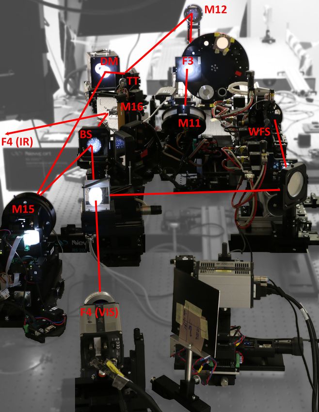
A&A proofs: manuscript no. tbd

                                    M1               M2                  M3
 focal length [mm]                  2506.35          519.40              1398.5
 optical footprint for 15000 [cm]   144              38.1                27.5
 f#                                 1.7              1.4                 5.1
 curvature radius [mm]              5012.70          1039.79             2797.00
 conic constant                     -1 (parabolic)   -0.306 (elliptic)   -0.538 (elliptic)
Table 1. Mirror properties for M1-M3.

                                                                astigmatism due to an oblique incidence on a focusing mir-
                                                                ror. However, we noticed that they created field-dependent
                                                                aberrations (mostly astigmatism and coma), prominent at
                                                                the design angles. Unfortunately, M12 and M15 could not
                                                                be aligned arbitrarily to minimize the aberrations, which
                                                                however never fully vanished, because of a fixed focal plane
                                                                and vignetting at other optical elements, plus their align-
                                                                ment tolerances were too strict. Additionally, there was a
                                                                lack of space in the optics lab to develop and install new
                                                                instrumentation. Therefore, we completely redesigned the
                                                                optics after M11, including new off-axis parabolic mirrors
                                                                to replace M12 and M15 and an improved instrument lay-
                                                                out.
                                                                    The new layout was devised based on the following cri-
                                                                teria:
                                                                 – More space for the science instruments and a future
                                                                   multi-conjugate adaptive optics (MCAO) via a different
                                                                   beam distribution while keeping all current capabilities.
                                                                 – Horizontal setup of the AO relay optics (for vibration
                                                                   reduction, stability, and easier alignment)
                                                                 – (Total) angle at M12/M15 = 8◦ (the two mirrors com-
                                                                   pensate each other). Angles < 8◦ are not possible due
                                                                   to the beamsplitter plate between M15 and M16.
                                                                 – 1:1 imaging of the AO relay optics between F3 and F4.
                                                                   Exit pupil telecentric (at infinity).
                                                                 – Perfect image quality in F4 over a radius of 60" (=2
                                                                   arcmin image diameter).
                                                                 – F3 at least 1000 mm after M11.
                                                                 – pupil size limited by the DM size.
                                                                 – A visible/infrared (VIS/IR) beamsplitter between M15
                                                                   and M16 reflects the VIS, only IR passes through to-
                                                                   wards GRIS. This improves the antireflection coatings
                                                                   both for the VIS and the IR elements. This beamsplitter
                                                                   is mounted on a rotating table and can be exchanged by
                                                                   e.g. a 50/50 beam splitter for special setups that require
                                                                   other wavelength distributions.
Fig. 1. GREGOR optical layout until F3                           – Small angles at mirrors for polarimetry.
                                                                 – DM-M15 parallel to M11-M12 (not strictly required, but
                                                                   simplifies the alignment).
ager (von der Lühe et al. 2012). Guest instruments, such as      – F4 IR unchanged (1420 mm from M11). M16-F4 IR shall
ZIMPOL for high-precision spectropolarimetry (Gandorfer            be on the same line as M11-F4 IR to keep the beam
& Povel 1997), or the GREGOR planet polarimeter (GPP,              angles, such that the GRIS instrument does not require
Gisler et al. 2016) were also regularly operated. The adap-        any changes.
tive optics (AO) was mounted on a vertical bench, which          – The wavefront sensor (WFS) shall be located after all
saves space, but may be disadvantageous in terms of vibra-         powered mirrors.
tions and alignment. The beam is collimated for the AO
after F3 via M12 and then reimaged via M15. The AO it-              The original and the new design are shown in Fig. 2. The
self consists of a tip-tilt (M13) and a deformable mirror       new off-axis parabolic (OAP) mirrors M12 and M15 are
(DM, M14). The setup is shown in the top panel of Fig. 2.       identical and compensate each other’s aberrations. Their
During the past two years, we realized that there were is-      paraxial focal length is 1978 mm and the off-axis distance
sues with beam stability, alignment, and the optical quality    is 277 mm. They are made from Zerodur with a diameter
induced by the two biconic mirrors M12 and M15. These           of 125 mm, thickness of 20 mm, with a silver coating. Their
mirrors originally featured biconic shapes to minimize the      measured surface error RMS is 6.9 and 5.2 nm for the two
Article number, page 2 of 10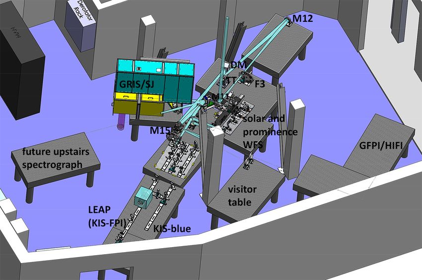
Lucia Kleint et al.: GREGOR: Optics Redesign and Updates from 2018-2020
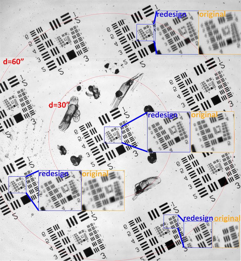
Fig. 2. Top image: Original GREGOR setup in side view from the vacuum exit window to F4. The location of the wavefront
sensor (WFS) is indicated with an arrow. The wavelength splitting was done with a pentaprism (PP) and the instrument focal
planes (F4) are shown for IR and VIS. Bottom image: New setup in top view. The VIS beam is reflected on the front side of the
beamsplitter plate (BS). It is then split by a beamsplitter with a fraction of the light going into the AO. The IR beam passes BS
and is then reflected on M16. The WFS is located after all mirrors with power.
mirrors, and this quality was achieved with two ion beam small deviations of properties (e.g. conic constant difference
figuring (IBF) polishing runs per mirror. of 2%, decenter of 5 mm, 1% deviation in paraxial radius).
The original and new MTFs and spot diagrams are The MTF remains nearly constant across the whole FOV,
shown in Fig. 3. The MTF for different field angles improves compared to a ∼50% drop in the original setup. There
with increasing wavelength, but obviously the spatial res- is space for a future MCAO and a future upstairs spec-
olution decreases at higher wavelength. We therefore show trograph, while all current instrument capabilities remain.
the MTF at 500 nm to illustrate the loss of contrast issues Additionally, all optical elements are accessible. Further-
of the original setup and the much better performance of more, all critical optical elements are motorized, so that
OAPs. All plots assume a maximum field of view (FOV) of their alignment is reproducible. During the redesign, the
12000 . number of motorized elements was increased from 7 to 13
and the motorization control interfaces were updated for
Figure 4 shows the new instrument layout and a photo manual and remote control. The wavefront sensor is located
of the setup in March 2020. GRIS and the slitjaw system after M15, thus able to correct for any static aberrations in-
remain. The new Fabry-Perot Interferometer (FPI), cur- duced by the relay optics. The wavelength splitting is per-
rently under development, will be in the straight beam and formed using a dichroic beamsplitter plate and no longer a
has minimal reflections. Parallel to it is its broadband chan- pentaprism, which is an advantage for polarimetry (smaller
nel for which we plan phase diversity, and a fast imager in angles). By using different beamsplitter plates, it is possi-
the blue. An insertable mirror, which can be rotated, sends ble to change the wavelength cutoff for the visible beam,
the light either to a visitor table, or to GFPI/HIFI, which is currently either to 650 nm or 900 nm. The location of the
now located near the entrance to the optics lab. One table beamsplitter plate in the beam simplifies the IR and visible
is saved for a future upstairs spectrograph, which can be coatings because now only the rear side of the beamsplitter
fed by rotating M16. About 75% of the mechanical parts plate requires a broad antireflection coating, while instru-
could be reused and were adapted for the new setup, which ments receive limited wavelength ranges and therefore can
accelerated the construction and fabrication. use mostly standard antireflection coatings, which are eas-
The new design has many advantages: By having a con- ier to obtain.
stant beam height above the optical tables, all alignment is
simplified. The off-axis parabolas have much better align- The new optical setup was installed in March 2020. The
ment tolerances than the former biconic mirrors. The PSF optical elements were aligned with a laser, which was trac-
remains near diffraction-limited in all field points, even for ing the beam backwards from F4. The laser direction was
Article number, page 3 of 10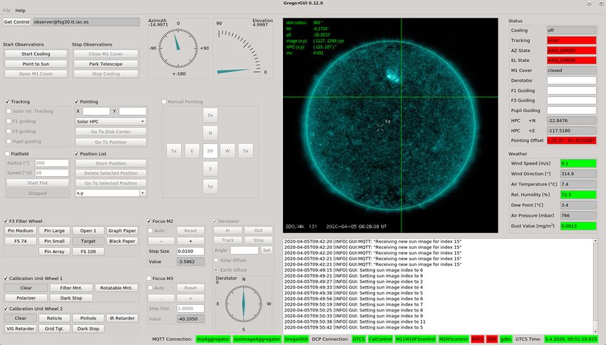
A&A proofs: manuscript no. tbd

Fig. 3. GREGOR spot diagrams for different wavelengths and MTF for 500 nm with max. FOV=12000 . The circle indicates the
Airy disk. Top row: original M12 and M15. Diffraction-limited performance is only achieved for the center of the FOV with a
very fast drop in contrast off-center. Note that this simulation is done for ideal M12 and M15 mirrors and our suspicion is that
their specs were not met, which would further worsen their properties. Middle row: New IR setup. The lateral shift is due to the
beamsplitter plate and 500 nm (red) is displayed to show that even the ZIMPOL guest instrument setup, which uses VIS in the
IR beam by using a custom beamsplitter plate, would still have diffraction-limited performance. Bottom row: New visible setup
with basically no loss of contrast for the whole field of 12000 . Note that all MTFs have good properties in the IR and therefore 500
nm is shown here.

aligned in azimuth from the original F4 GRIS location to           front sensor. This gave us the response of the 256 actuators.
a plummet hanging from the exit window, which defined              A pinhole in the AO F4 was used to measure the subaper-
the vertical optical axis of the telescope. During the back-       ture reference positions for the perfect wavefront. Then we
wards tracing, the beam angles were measured for M15, the          locked the AO on a USAF target in F3, which was immedi-
DM and M12 and the mirrors shifted and tilted if neces-            ately sharp over the whole field of view in the science cam-
sary to match the design values. The laser was reflected           era in F4 VIS. The improvement compared to the old relay
upwards into the vertical optical axis by M11, where it co-        optics was immediately noticeable and can be attributed to
incided with the plummet line. The wavefront sensor was            the pair of off-axis parabolic mirrors with a small and equal
only adapted to its change of location, but its properties         reflection angle.
remain. We then calibrated the AO by applying Hadamard
shapes to the DM and measuring the response of the wave-              Figure 5 shows a test target recorded on March 21, 2020.
                                                                   It was recorded directly in the visible F4, with an expo-
Article number, page 4 of 10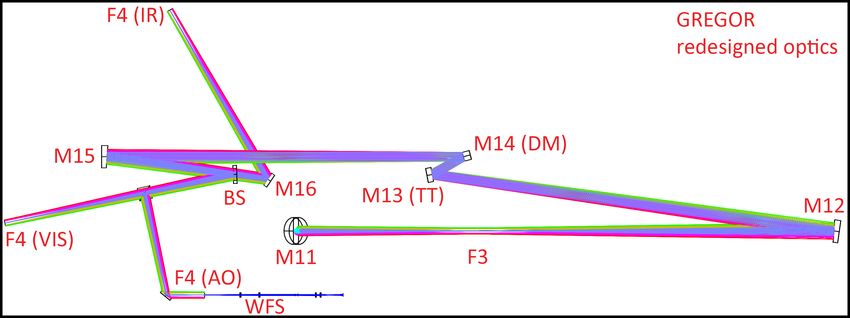
Lucia Kleint et al.: GREGOR: Optics Redesign and Updates from 2018-2020

Fig. 4. Left: New instrument layout at GREGOR. GRIS (yellow) with the SJ system (green box above GRIS) are the only optics
that remain in the same place, but all original instrument combinations remain. The AO is now horizontal and the new KIS FPI
is drawn towards the window. The empty tables are for temporary visitor setups and for GFPI/HIFI. Right: Photo of the setup
as installed in March 2020. The red line traces the beam.

sure time of 3 ms at 393.55 ± 1.1 nm. No AO mode offsets          result in non-optimal wavefront reconstruction and correc-
were applied or necessary. The pixel scale is 000.023 pixel−1 .   tion / increased wavefront error, which is why we could not
The figure is a composite of two images: the camera was           fully exploit the maximum number of corrected modes in
shifted in height to record all subtargets. This figure demon-    the past.
strates that the redesign was successful because all targets          It was therefore decided in 2014 to replace M2 with
are sharp across the whole field of view and the correct ele-     one made of Zerodur. A call for tender was issued, this
ment (5th group, 5th element) is resolved in all subtargets,      time with a much stricter specification on the allowed WFE.
some of which are shown magnified in the blue boxes. No           The WFE Φ was specified in terms of a structure function
astigmatism or coma is visible. For comparison, the orange        DΦ (r), which describes the error at different spatial scales:
boxes show a test target, taken with the original optics at
396 nm on July 19, 2019. It is clearly visible that previ-
ously, locations outside of the image center showed strong                                        2
astigmatism (“shadows”), consistent with the MTF shown            DΦ (r) = avg([Φ(x + r) − Φ(r)] )                            (1)
in Fig. 3.
                                                                  where r denotes different separations of (randomly) selected
                                                                  points. The outer diameter was specified to 430 mm. Be-
2.2. M2
                                                                  cause M1 is stopped down to 1.44 m due to its polishing
The original secondary mirror (M2) was fabricated from            quality, the optical footprint on M2 is 381 mm, but up to
silicone carbide (Cesic) a material of high stiffness, whose      385 mm are of sufficient polishing quality.
thermal properties are favorable to absorb the 1.3 W from             There were some issues during fabrication and the specs
the incoming sunlight after the primary field stop when as-       could not be met with conventional polishing methods.
suming that each mirror absorbs 10% of its incoming light.        However, after using IBF, the mirror’s surface is now among
Unfortunately, the Cesic surface could not be polished well       the best at GREGOR. The new M2 was installed in July
enough and in the end of the polishing the original M2 had        2018 and the improvements in contrast after its installation
an rms wavefront error (WFE) of ∼40 nm, mostly in the             at GREGOR were noticeable even before carrying out any
shape of concentric rings as shown in Fig. 6. These rings         acceptance testing. They are difficult to quantify, but we
were of the same scale size as the AO subapertures, which         estimate an improvement of the contrast of a factor 1.5-2
means that the AO could not “see” them and therefore was          in the WFS. Since then, the adaptive optics easily locks
not able to correct them. Such mid-frequency errors lead to       on granulation, even during bad seeing. Figure 6 shows the
a severe reduction in contrast both in the WFS and in the         interferograms of the original and the new M2. To display
science camera. The low WFS contrast then leads to a low          both on the same scale (±80 nm WFE), data from the
signal to noise ratio of the wavefront reconstruction and a       original M2 had to be clipped. Figure 7 shows the struc-
reduced performance of the AO, especially when locking on         ture functions of original and new M2 and the specifications
granulation. Furthermore, the unsensed mid-frequency er-          from the call for tender, which were clearly exceeded. This
rors lead to spatial aliasing, which means that insufficient      was the last Cesic mirror to be replaced and GREGOR now
spatial points are available to determine the wavefront, and      contains only Zerodur mirrors.
                                                                                                      Article number, page 5 of 10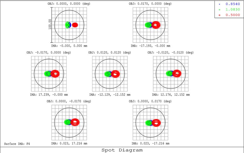
A&A proofs: manuscript no. tbd

Fig. 5. Image of a test target obtained after the redesign. The blue insets show magnified sections, the orange insets demonstrate
the comparison to the original optics setup, which suffered from astigmatism and coma outside of the image center. The redesigned
optics are perfectly sharp across the whole field of view. The image scale is indicated with red circles, whose diameters are specified
in the figure.

2.3. Derotator                                                      the derotator control in functionality and design. The dero-
                                                                    tator can now be controlled from the GREGOR GUI and
The derotator consists of M8-M10 and was installed in 2016.         we calibrated its orientation, such that observers can sim-
M8 and M10 are tilted by 30◦ , leading to incident beam             ply insert the desired solar angle (e.g. 0 for north-south)
angles of 60◦ , which is not optimal for polarimetry and            for the spectrograph slit orientation and all calculations are
requires careful calibration (Hofmann et al. 2012). By ro-          performed internally.
tating about the optical axis, the derotator counteracts the
image rotation introduced by the alt-az telescope mount.
The image rotation is the sum of parallactic angle + az-            2.4. Alignment
imuth - zenith distance - solar p0 angle + an offset for the
desired orientation. The required derotator rotation is half        GREGOR has very tight alignment tolerances due to its
of the image rotation. The image rotation rate is highest           fast beam. It is therefore nearly impossible to align the tele-
in June when the Sun nearly reaches zenith and exceeds 5◦           scope visually (using lasers) and past experience has shown
per minute then, while it generally remains below 0.5◦ per          larger aberrations after each recoating. It is possible that
minute before 11 UT during nearly the whole year.                   each M1 removal and remounting has modified its position
    The original developer GUI was used by observers to             because even a 0.001 degree tilt is noticeable in the aber-
control the derotator for several years. In 2019 we enhanced        rations measured by the AO, but not visually. In the past,
Article number, page 6 of 10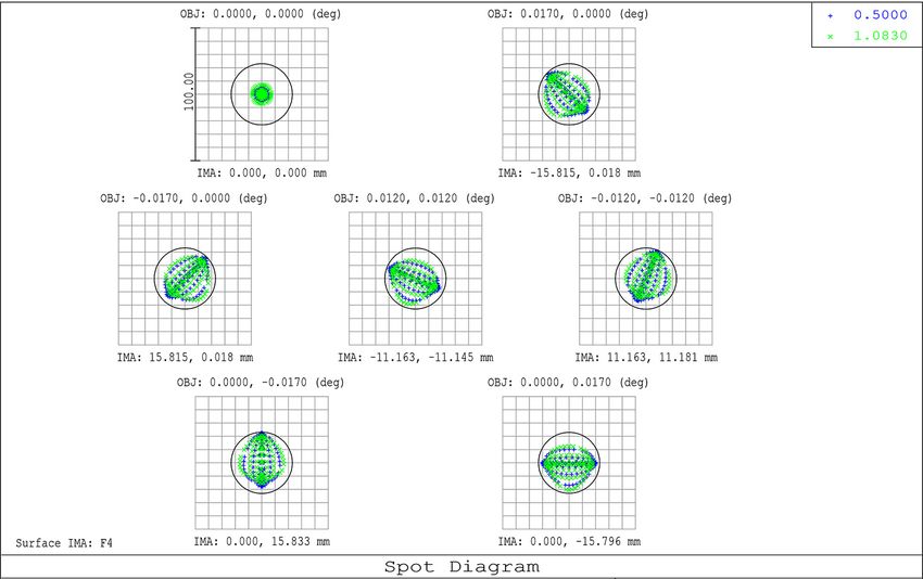
Lucia Kleint et al.: GREGOR: Optics Redesign and Updates from 2018-2020

Fig. 6. Comparison of the interferograms of original and new M2. The display range is ±80 nm for both, showing wavefront errors,
which are a factor of 2 larger than surface errors. Some dust and finger prints explain the small imperfections on the interferogram
of the new M2. The WFE rms is 39 nm and 8 nm for original and new M2, respectively.

                                                                       M1 actively controlled, which would enable us to perform
                                                                       this procedure in minutes instead of days.
                                                                            2) Because M1 and M2 are not perfectly aligned with the
                                                                       optical axis, even via the above procedure, a beam wobble
                                                                       is introduced downstream. For the remaining small beam
                                                                       deviations, we programmed a “beam tracker”, which con-
                                                                       sists of a webcam pointing to F3 and a program that auto-
                                                                       matically monitors the beam position and sends signals to
                                                                       tilt M5 to compensate for the diurnal variation. The beam
                                                                       tracker program fits a circle to the beam in F3 and keeps its
                                                                       position constant, which stabilized all focal planes after F3.
                                                                       Full stability can only be achieved if also the pupil is stabi-
                                                                       lized. This is done by measuring the intensity distribution
                                                                       on the WFS and an offset of the pupil is therefore directly
                                                                       visible. The AO controls the tilt of M11 and because the
                                                                       DM is exactly in a pupil plane, all subsequent pupils are
Fig. 7. Structure function. 106 randomly selected points were          stabilized. M11 is located 1000 mm from F3, while M5 is
used to calculate differences in the WFE according to Eq. 1.           located 808 mm from a pupil. While both mirrors are not
The new M2 is significantly better than the requirements. The          perfectly located in pupil or image planes, and therefore
larger scatter near smaller spatial scales is due to averaging fewer   both influence the image and pupil motions, the effect on
points when binning. The current optical footprint on M2 is 381        the pupil (when moving M5) or the image (when moving
mm.                                                                    M11) planes is minimal and both trackers converge itera-
                                                                       tively within seconds to a centered image in F3 and pupil
                                                                       on the DM.
M2 was shifted and tilted to counteract these aberrations,
but after the fourth recoating in 2017, the required shifts
reached several mm.                                                    3. Infrastructure
    This issue was solved in two ways: 1) We devised a new             3.1. Vibrations
method to align M1 by using the AO and successfully car-
ried out the alignment in May 2019. The method involves                Vibrations are a common problem in telescopes and de-
using the force actuators on the back of M1 and creating               pending on their frequencies cause significant issues in the
a “response matrix” of each actuator. It can then be cal-              data. We measured vibrations at GREGOR and improved
culated in which positions the actuators should be to min-             several culprits that introduced vibrations: the mirror cool-
imize the aberrations. The fine tuning is afterwards done              ers were insulated better from the floor, an optical table
via direct feedback from the AO. It turned out that the ac-            was replaced with a more stable version, the adaptive op-
tuators for tilt had to be moved significantly in May 2019,            tics setup was fortified with additional struts before it was
which may support the hypothesis that remounting M1 in-                made completely horizontal, additional supports were con-
troduces mirror tilt. In the future, we will explore making            structed for the slitjaw system, and the air conditioning is
                                                                                                         Article number, page 7 of 10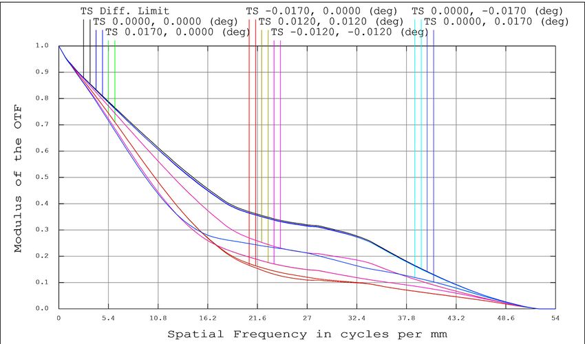
A&A proofs: manuscript no. tbd

being investigated because we observed it to cause vibra-        servations and leads to e.g. fewer missing calibration data.
tions at 50, 60 and 125 Hz. We found that the air used for       Additionally, every observer writes an observing report af-
the cooling of M1, which is distributed to the backside of M1    ter their observing run detailing problems (if any) and every
via fans, seems to cause vibrations of M1 around 200 and         maintenance is documented with maintenance reports that
390 Hz. Vibrations below 100 Hz can be mostly corrected by       are accessible to all partners via an internal website. Er-
the AO system, but the peaks around 200 and 390 Hz un-           rors and bugs are reported via a ticketing system for better
fortunately cannot and are also seen in AO power spectra.        traceability of all actions.
Their amplitude can be influenced by the fan speed of the
M1 cooling and in certain outside temperature conditions,
it is possible to reduce the amplitude by ∼ 75%. However,        3.5. Observing room
a universally applicable solution is currently being investi-
gated because a first attempt of stiffening the housing of       GREGOR’s observing room is located on the third floor,
the coolers did not reduce the vibrations. In general, the       two floors below the optics lab. It features three control
combined measures taken so far have reduced the overall          computers, one of which is usually used for telescope and
vibrations by at least a factor of 10.                           AO controls and the other two are available to control in-
                                                                 struments. The screens can be mirrored in Freiburg for re-
                                                                 mote observations or observing support. We installed 4 we-
3.2. Seeing                                                      bcams on top of the neighboring VTT telescope to monitor
                                                                 the clouds and a new weather screen is mounted in the
As the air surrounding the telescope heats up during the         observing room showing the 360◦ view, solar activity, and
day, the image quality degrades (“seeing”). At GREGOR            seeing and weather-plots. The background automatically
this often translates into r0 values that drop by a factor of    turns red in case a weather limit is exceeded, for example
4 from early morning to afternoon. We therefore repainted        if the wind exceeds 20 m/s or if the humidity exceeds 80%,
all panels on the East side of the building with a special       indicating the need to close the telescope. This has solved
paint that keeps the panels within one degree of the ambient     discussions between observers and assistants whether one
temperature by emitting in the infrared. Additionally, we        should or should not close the telescope.
repainted the flagstones and the tiles on the roof of the
building with special paint based on titanium oxide and our
temperature measurements with an infrared camera have
shown that the floor temperature decreased by at least 2
degrees.                                                         4. Instrumentation
    Temperature logging in the optics lab, which was in-
stalled in 4/2019, shows diurnal variations with an ampli-       In this Section we only review upgrades made by KIS from
tude of about 0.5 ◦ C, which may contribute to the seeing        2017-2020. There were no changes to BBI, the GREGOR
in the optics lab and their cause is being investigated. As      planet polarimeter (GPP) and the guest instrument ZIM-
a first step, we created a new server room adjacent to the       POL.
optics lab and are in the process of relocating most electron-
ics/computers that contribute to heating the optics lab.
                                                                 4.1. Slitjaw System

3.3. Electric Installations                                      The slitjaw (SJ) system is a context imager for the GRIS
                                                                 instrument. It was completely redesigned in 2018 to provide
In 2017 the old uninterruptible power supply (UPS) was re-       diffraction-limited images. The GRIS slit mask and integral
placed with a new 3-phased UPS, which doubled the power          field unit (IFU) mask are inclined by 15◦ , which reflects the
output (to 40 kVA). The new control of the UPS was pro-          beam upwards (beam angle 2x15◦ ) as shown in the optical
grammed by KIS and installed by a company. Since 02/2019         layout in Figure 8. A motorized lens with a focal length
all critical systems of GREGOR are on UPS. During power          of 750 mm automatically adjusts its position depending on
outages, the UPS bridges the time until the Diesel gener-        the slit position during a scan to keep a constant distance
ator starts. In case of catastrophic failures, the UPS has       between the (inclined) slit mask and the lens. The light is
enough power to supply GREGOR for about 30 minutes,              then distributed onto 3 horizontal rails above the SJ ta-
which allows for a controlled shutdown, especially of the        ble. The lowest rail can be used for temporary setups. The
dome, which must be closed to protect the telescope from         middle rail gets 80% of the incoming light and features an
weather.                                                         H-α Lyot filter with a passband of 0.4 Å for chromospheric
                                                                 context images. The upper rail contains a 777 nm filter
                                                                 and shows photospheric context images. Both context im-
3.4. Documentation                                               ages use a f=300 mm lens, which together with Prosilica
Changes that are not documented can lead to frustration          GT2050 cameras with 2048 × 2048 pixels (5.5 µm × 5.5
when systems behave differently than during the last time.       µm) lead to a plate scale of 000.05 pixel−1 .
We have therefore introduced a version-controlled reposi-            For stability reasons, the whole SJ/GRIS optical table
tory of GREGOR documents, partially open to the pub-             was replaced, which reduced vibrations by one order of mag-
lic via http://www.leibniz-kis.de/de/observatorien/              nitude. Additionally, supports were constructed, which sta-
gregor/documentation/. These include manuals, check-             bilize the overhanging part of the setup. A slit scanning
lists, technical notes, and requirements specifications. All     device was developed, by building the mechanics and by
instruments now have checklists that are also prominently        programming the controls, which allows to scan areas of
displayed in the observing room, which simplifies the ob-        the Sun.
Article number, page 8 of 10
Lucia Kleint et al.: GREGOR: Optics Redesign and Updates from 2018-2020

                                                                   Fig. 9. The GREGOR GUI. It allows us to control all essential
                                                                   telescope systems, such as positioning, pointing, filter wheels,
                                                                   calibration optics, focusing, and the derotator. The right side
                                                                   contains a display of current solar data, a system and weather
                                                                   status, and an event log.

Fig. 8. The SJ system installed at GREGOR. The upper two
channels are continuum and H-alpha, respectively, while the bot-   content changes. The advantage of this approach is that fu-
tom channel is currently not used.                                 ture applications, for example a weather status page, can
                                                                   also be programmed to subscribe to the MQTT broker to
4.2. Adaptive Optics                                               obtain the relevant data. This will avoid past issues when
                                                                   too many simultaneous commands created issues with the
The numerous enhancements of the GREGOR adaptive op-               network and system load. Safety-relevant features, such as
tics (Berkefeld et al. 2012) will be described in a forthcom-      who can take control, had to be considered in addition
ing publication, with only a short summary given here. The         to user-friendliness and simplicity of operation: User IDs
main enhancements of the AO include that the AO takes              are published using the same underlying mechanism cre-
control of the telescope in closed-loop operations. By send-       ating a UID-specific command topic and the commander
ing small positioning commands to the telescope, based on          service subscribes to this to receive commands from only
the tip-tilt measurements, the AO can track the desired fea-       one commanding instance (e.g. a GREGOR GUI instance)
ture, thus compensating for solar rotation, or positioning         at a time. The layout of the GUI is shown in Fig. 9 and was
issues, which may exceed the range of regular tip-tilt cor-        structured, such that telescope operation is on the top, then
rection. It also controls the z-position of M2 for the optimal     pointing, positioning and flatfielding, and control of motors
focus, which needs to be adapted during the day because            (filter wheels, derotator, focusing) on the bottom. The right
of temperature and gravity changes, which lead to small            side of the GUI displays the solar image in any desired SDO
variations in the focal distance between M1 and M2, but            wavelength, status data (weather, systems, seeing) and a log
which are too large to be corrected by a simple focus offset       file.
via the DM. Furthermore, the AO automatically sets the
ideal number of modes for the correction, depending on the
seeing and the target, and can also update the reference
                                                                   6. Management
image periodically if desired.
                                                                   6.1. Two observing seasons
5. Control Systems                                                 In addition to the optical and facility upgrades, we also
Most of the GREGOR GUIs were designed to be engineer-              introduced policy changes. One was to make the observing
ing GUIs and therefore not particularly user-friendly for          time planning more flexible by having two observing seasons
first-time observers. Before 2019, an observer therefore had       each year. Season 1 normally lasts from April-August and
to use more than 10 separate GUIs to control the telescope         season 2 from August-December. This greatly facilitated
functions. A workshop was organized at KIS with represen-          dealing with unexpected issues, such as mirror recoatings
tatives from each institute (KIS, MPS, AIP, IAC) during            that became urgent during the year. It also is advantageous
which requirements for a new observing GUI were defined            for scientists when they do not have to wait for a year to
that would simplify the operation and display all relevant         apply for observing time if they have a good scientific idea
functions, plus add some new functionality, in one GUI. The        right after a deadline.
new GUI was developed within a year, and is operational
since 2019.                                                        6.2. Access and permissions
    It is programmed in QT and based on a publisher-
subscriber principle using MQTT as protocol. A data ag-            The other policy change was a much stricter control of tele-
gregation service collects all data from all subsystems and        scope access and the limitation of personnel that is allowed
provides these data, plus external data such as current so-        to modify optics. Visitors no longer suddenly appear in the
lar images published by other dedicated services, via topics       optics lab during observations. The alignment is also much
on a MQTT broker. Multiple subscribers, e.g. GREGOR                more stable and there are fewer unexpected changes and
GUIs, can subscribe to these topics to be updated if their         issues. After 2 years of observing with the new system, the
                                                                                                      Article number, page 9 of 10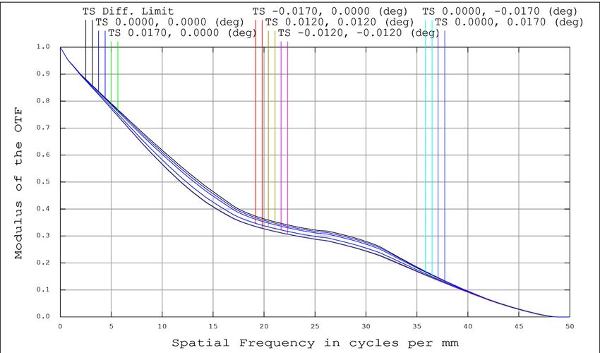
A&A proofs: manuscript no. tbd

observing reports are generally very positive and campaigns         New alignment methods were developed and solutions
without good data are rare.                                     were found to optimize the beam stability and reduce the
                                                                vibrations. The telescope is now controlled by a dedicated
                                                                GUI, which includes the functionality for all subsystems.
6.3. Technical Maintenance and Assistance                       The observing room was optimized, with dedicated work
GREGOR is a very complex telescope for its size. It is oper-    stations to control the telescope and instruments and a
ated with a technical observing assistant on each observing     weather monitor to improve the safety of noticing weather-
day, who is responsible for the telescope operation and the     related telescope closure conditions. Most systems are docu-
hardware. About 200 person-days are spent for assistance,       mented with manuals, checklists and technical notes, which
with assistant campaigns lasting 2-3 weeks. While this num-     are accessible in a version-controlled database, based on a
ber is high, having qualified operators for the telescope and   model for documentation of space missions. Management
AO increased GREGOR’s productivity significantly.               and policy changes further improved the stability of the
    Technical maintenance is performed mostly during the        telescope and consistently obtaining scientifically valuable
winter break. More than 500 person-days are spent annually      data.
on technical work at the telescope, ranging from recoating      Acknowledgements. Operating GREGOR would not be possible with-
mirrors, optics, mechanics, electronics, to updates of the      out the dedicated KIS technical staff who are all very gratefully ac-
infrastructure.                                                 knowledged. In particular, we would like to thank Oliver Wiloth, An-
                                                                dreas Bernert, Stefan Semeraro, Frank Heidecke, Michael Weisss-
                                                                chädel, Clemens Halbgewachs, Tobias Preis, Peter Markus, Peter
                                                                Caligari, Marco Günter, Markus Knobloch, Roland Fellmann, Chris-
7. Impact of the Upgrades on Observations                       tine Fellmann, Bruno Femenia, Daniel Gisler, and Sylvia Nadler.
                                                                We also thank Göran Scharmer and an anonymous referee for help-
Observers at GREGOR will notice many changes and en-            ful comments on the manuscript. The 1.5-meter GREGOR solar tele-
hancements. It is now possible to keep the AO locked on the     scope was built by a German consortium under the leadership of the
quiet Sun for time periods exceeding a few dozen minutes.       Leibniz-Institute for Solar Physics (KIS) in Freiburg with the Leib-
                                                                niz Institute for Astrophysics Potsdam, the Institute for Astrophysics
For objects with high contrast, such as sunspots and pores,     Göttingen, and the Max Planck Institute for Solar System Research in
the potential observing time spans hours. Observers will        Göttingen as partners, and with contributions by the Instituto de As-
also notice a strong increase in image sharpness, especially    trofisica de Canarias and the Astronomical Institute of the Academy
outside of the central area of the field of view. This should   of Sciences of the Czech Republic.
enable studies of larger regions, for example active regions,
including penumbrae, flows, large filaments, or flares. In
terms of user-friendliness, the enhancements of the dero-       References
tator, the control systems, especially the GREGOR GUI,
and the technical infrastructure, allow observers to quickly    Berkefeld , T., Schmidt, D., Soltau, D., von der Lühe, O., & Heidecke,
                                                                   F. 2012, Astronomische Nachrichten, 333, 863
point the telescope to the desired position and image orien-    Berkefeld, T., Schmidt, D., Heidecke, F., & Fischer, A. 2018, in Soci-
tation, with fast changes possible for target of opportunity       ety of Photo-Optical Instrumentation Engineers (SPIE) Conference
observations. Observers can also expect to be able to work         Series, Vol. 10703, Proc. SPIE, 107033A
more efficiently, because documentation and checklists are      Bianda, M., Berdyugina, S., Gisler, D., et al. 2018, A&A, 614, A89
                                                                Collados, M., López, R., Páez, E., et al. 2012, Astronomische
available for instruments and systems, which for example           Nachrichten, 333, 872
avoids that important calibration data are missed.              Dhara, S. K., Capozzi, E., Gisler, D., et al. 2019, A&A, 630, A67
    Several further enhancements are planned for future         Gandorfer, A. M., & Povel, H. P. 1997, A&A, 328, 381
observations: A new spectropolarimeter based on Fabry           Gisler, D., Berkefeld, T., & Berdyugina, S. 2016, in Society of Photo-
                                                                   Optical Instrumentation Engineers (SPIE) Conference Series, Vol.
Perot Interferometers is in development, which will allow          9906, Proc. SPIE, 99065E
quasi-simultaneous magnetic field measurements of a field       Goode, P. R., Coulter, R., Gorceix, N., Yurchyshyn, V., & Cao, W.
of view exceeding 5000 in the photosphere and in the chro-         2010, Astronomische Nachrichten, 331, 620
mosphere. Another planned upgrade involves the adaptive         Hofmann, A., Arlt, K., Balthasar, H., et al. 2012, Astronomische
optics, which will be equipped with an H-α filter and thus         Nachrichten, 333, 854
                                                                Jing, J., Xu, Y., Cao, W., et al. 2016, Scientific Reports, 6, 24319
be able to lock on e.g. prominences and spicules near the       Kleint, L., & Gandorfer, A. 2017, Space Sci. Rev., 210, 397
solar limb, thus improving the image stabilization and qual-    Penn, M. J. 2014, Living Reviews in Solar Physics, 11, 2
ity for off-limb observations.                                  Puschmann, K. G., Denker, C., Kneer, F., et al. 2012, Astronomische
                                                                   Nachrichten, 333, 880
                                                                Scharmer, G. B., Bjelksjo, K., Korhonen, T. K., Lindberg, B., & Pet-
                                                                   terson, B. 2003, in Society of Photo-Optical Instrumentation En-
8. Summary and Conclusions                                         gineers (SPIE) Conference Series, Vol. 4853, Proc. SPIE, ed. S. L.
                                                                   Keil & S. V. Avakyan, 341–350
GREGOR has undergone significant changes from 2018-             Scharmer, G. B., de la Cruz Rodriguez, J., Sütterlin, P., & Henriques,
2020. New relay optics allow us to reach diffraction-limited       V. M. J. 2013, A&A, 553, A63
optical quality over the whole field of view. The new instru-   Scharmer, G. B., Löfdahl, M. G., Sliepen, G., & de la Cruz Rodríguez,
ment distribution allows us to plan for future upgrades of         J. 2019, A&A, 626, A55
                                                                Schmidt, D., Gorceix, N., Marino, J., et al. 2016, in Society of Photo-
instrumentation. The replacement of the last Cesic mirror          Optical Instrumentation Engineers (SPIE) Conference Series, Vol.
with one made of Zerodur improved the contrast notice-             9909, Proc. SPIE, 990929
ably. A new slitjaw system provides diffraction-limited con-    Schmidt, W., von der Lühe, O., Volkmer, R., et al. 2012, Astronomis-
text images in the photosphere and in the chromosphere.            che Nachrichten, 333, 796
                                                                von der Lühe, O., Schmidt, W., Soltau, D., et al. 2001, Astronomische
The adaptive optics was enhanced to optimize many of the           Nachrichten, 322, 353
previously manual telescope functions, such as tracking and     von der Lühe, O., Volkmer, R., Kentischer, T. J., & Geißler, R. 2012,
focusing. The derotator functionality was enhanced and its         Astronomische Nachrichten, 333, 894
orientation calibrated.
Article number, page 10 of 10
You can also read