The Large Hadron Collider, a personal recollection
←
→
Page content transcription
If your browser does not render page correctly, please read the page content below
Prog. Theor. Exp. Phys. 2014, 02A102 (20 pages)
                                                                                                                DOI: 10.1093/ptep/ptt117

Implications of Higgs Particle Discovery

The Large Hadron Collider, a personal recollection
Lyndon Evans1,2,∗
1
  CERN, Meyrin, CH-1211, Geneva 23, Switzerland
2
  Imperial College London, London SW7 2HZ, UK
∗
  E-mail: lyn.evans@cern.ch
Received November 21, 2013; Accepted December 2, 2013; Published February 10, 2014

                     ...............................................................................
                     The construction of the Large Hadron Collider (LHC) has been a massive endeavor spanning
                     almost 30 years from conception to commissioning. Building the machine with the highest possi-

                                                                                                                                                        Downloaded from http://ptep.oxfordjournals.org/ by guest on September 25, 2015
                     ble energy (7 TeV) in the existing LEP tunnel of 27 km circumference and with a tunnel diameter
                     of only 3.8 m has required considerable innovation. The first was the development of an idea first
                     proposed by Bob Palmer at Brookhaven National Laboratory in 1978, where the two rings are
                     integrated into a single magnetic structure. This compact 2-in-1 structure was essential for the
                     LHC due to both the limited space available in the existing Large Electron–Positron collider tun-
                     nel and the cost. The second innovation was the bold move to use superfluid helium cooling on
                     a massive scale, which was imposed by the need to achieve a high (8.3 T) magnetic field using
                     an affordable Nb-Ti superconductor. In this article, no attempt is made to give a comprehensive
                     review of the machine design. This can be found in the LHC Design Report [1], which gives
                     a detailed description of the machine as it was built and comprehensive references. A more
                     popular description of the LHC and its detectors can be found in [2]. Instead, this is a more
                     personal account of the project from approval to commissioning, describing some of the main
                     technologies and some of the trials and tribulations encountered in bringing this truly remarkable
                     machine alive.
                     ...............................................................................
                     Subject Index               C30, G00

1.     Approval of the LHC
The Large Hadron Collider (LHC) had a difficult birth. Although the idea of a large proton–proton
collider at CERN had been around since at least 1977, the approval of the Superconducting Super
Collider (SSC) in the United States in 1987 [3] put the whole project into doubt. The SSC, with a
center-of-mass energy of 40 TeV was almost three times more powerful than what could ever be built
at CERN. It was only the resilience and conviction of Carlo Rubbia, who shared the 1984 Nobel Prize
in physics for the discovery of the W and Z bosons, that kept the project alive. Rubbia, who became
Director General of CERN in 1989, argued that, in spite of its disadvantage in energy, the LHC
could be competitive with the SSC by having a luminosity an order of magnitude higher than could
be achieved with the SSC, and at a fraction of the cost. He also argued that the LHC would be more
versatile. As well as colliding protons, it would be able to accelerate heavy ions to world-beating
energies at little extra cost.
  The SSC was eventually cancelled in 1993 [4]. This made the case for the building of the LHC
even stronger, but the financial climate in Europe at the time was not conducive to the approval of a

© The Author(s) 2014. Published by Oxford University Press on behalf of the Physical Society of Japan.
This is an Open Access article distributed under the terms of the Creative Commons Attribution License (http://creativecommons.org/licenses/by/3.0/),
which permits unrestricted use, distribution, and reproduction in any medium, provided the original work is properly cited.
PTEP 2014, 02A102                                                                             L. Evans

large project. CERN’s largest contributor, Germany, was struggling with the cost of reunification and
many other countries were trying to get to grips with the problem of meeting the Maastricht criteria
for the introduction of the single European currency.
   During the course of 1993, an extensive review was made in order to reduce the cost as much
as possible, although a detailed cost estimate was particularly difficult to make since much of the
research and development on the most critical components was still to be done. In December 1993, a
plan [5] was presented to the CERN Council to build the machine over a ten-year period by reducing
the other experimental programs of CERN to the absolute minimum, with the exception of the full
exploitation of the Large Electron–Positron (LEP) collider, which was the flagship machine of the
decade.
   Although the plan was generally well received, it became clear that two of the largest contributors,
Germany and the United Kingdom, were very unlikely to agree to the budget increase required. They
also managed to get Council voting procedures changed from a simple majority to a double majority,
where much more weight was given to the large contributors so that they could keep control.

                                                                                                          Downloaded from http://ptep.oxfordjournals.org/ by guest on September 25, 2015
   On the positive side, after the demise of the SSC, a US panel on the future of particle physics [6]
recommended that “the government should declare its intentions to join other nations in constructing
the LHC.” Positive signals were also being received from India, Japan, and Russia.
   In June 1994, the proposal to build the LHC was made once more. Council adopted a very unusual
procedure in which the vote on the Resolution was opened so that countries in a position to vote could
do so, but neither the vote nor the Council Session was closed [7]. Seventeen member states voted
to approve the project. However, because of the newly adopted double voting procedure, approval
was blocked by Germany and the UK, who demanded substantial additional contributions from the
two host states, France and Switzerland, claiming that they obtained disproportionate returns from
the CERN budget. They also requested that financial planning should proceed under the assumption
of 2% annual inflation, with a budget compensation of 1%, essentially resulting in a 1% annual
reduction in real terms.
   In order to deal with this new constraint, CERN was forced to propose a “missing magnet” machine
where only two-thirds of the dipole magnets needed to guide the beams on their quasi-circular orbits
would be installed in a first stage, allowing the machine to run with reduced energy for a number
of years, eventually upgrading to full energy. This would have been a very inefficient way of build-
ing the machine, costing more in the long run but saving some 300 million Swiss francs in the first
phase. This proposal was put to Council in December 1994. After a round of intense discussions
between France, Switzerland, Germany and the UK, the deadlock concerning extra host-state con-
tributions was broken when France and Switzerland agreed to make extra voluntary contributions
in the form of a 2% annual inflation adjustment, compared with the 1% adjustment from the other
member states. In the continuation of the 100th Session of Council, still open from the June meeting,
the project was finally approved [8] for two-stage construction, to be reviewed in 1997 after the size
of the contribution offered by non-member states interested in joining the LHC program would be
known. The tough negotiations with France and Switzerland were couched in diplomatic language
in the Considerata of the Council Resolution: “[The CERN Council] notes with gratitude the com-
mitments of France and Switzerland to make voluntary contributions to help and accelerate the LHC
Project.”
   There followed an intense round of negotiations with potential contributors. The first country to
declare a financial contribution was Japan, which became an observer to the CERN Council in June
1995.

                                                 2/20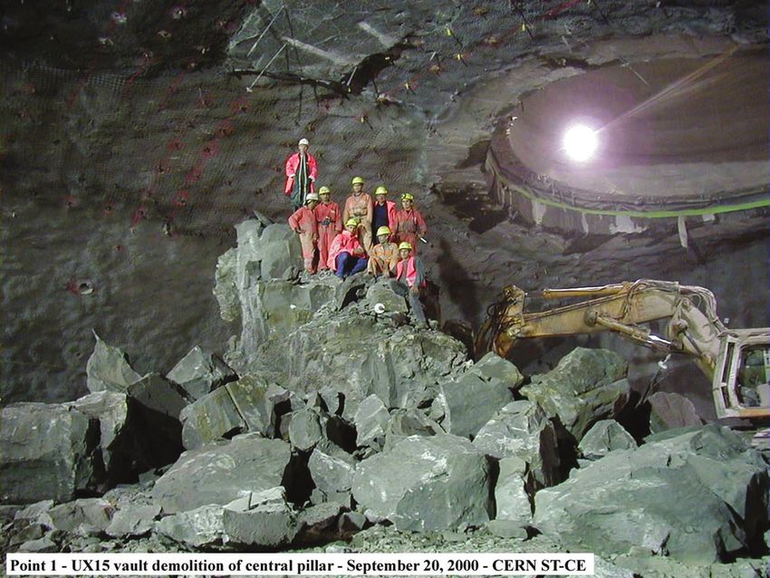
PTEP 2014, 02A102                                                                                 L. Evans

   The declaration from Japan was quickly followed by India and Russia in March 1996 and by Canada
in December.
   A final sting in the tail came in June 1996 from Germany who unilaterally announced that, in order
to ease the burden of reunification, it intended to reduce its CERN subscription by between 8% and
9%. Confining the cut to Germany proved impossible. The UK was the first to demand a similar
reduction in its contribution, in spite of a letter from the UK Minister of Science during the previous
round of negotiations stating that the conditions were “reasonable, fair and sustainable”. The only
way out was to allow CERN to take out loans, with repayment to continue after the completion of
LHC construction.
   In the December 1996 Council, Germany declared that “a greater degree of risk would inevitably
have to accompany the LHC.” The project was approved for single-stage construction, with the deficit
financed by loans. It was also agreed that the final cost of the project was to be reviewed at the half-way
stage with a view to adjusting the completion date. With all contingency removed, it was inevitable
that a financial crisis would occur at some time, and this was indeed the case when the cost estimate

                                                                                                              Downloaded from http://ptep.oxfordjournals.org/ by guest on September 25, 2015
was revised upwards by 18% in 2001. Although this was an enviable achievement for a project of
such technological complexity and with a cost estimate from 1993 before a single prototype had been
made, it certainly created big waves in Council. CERN was obliged to increase the level of borrowing
and extend the construction period (which was anyway necessary on technical grounds for both the
machine and detectors).
   In the meantime, following the recommendation of the US panel, and in preparation for a substan-
tial contribution, The US Department of Energy, responsible for particle physics research, carried
out an independent review of the project [9]. They found that “the accelerator-project cost estimate
of 2.3 billion in 1995 Swiss francs, or about $2 billion U.S., to be adequate and reasonable.” More-
over, “[m]ost important of all, the committee found that the project has experienced and technically
knowledgeable management in place and functioning well. The strong management team, together
with the CERN history of successful projects, gives the committee confidence in the successful com-
pletion of the LHC project.” In December 1997, at a ceremony in Washington in the splendid Indian
Treaty Room of the White House Annex, an agreement was signed between the Secretary of Energy
and the President of the CERN Council.
   After a shaky start and a mid-term hiccup, the project has proceeded reasonably smoothly to
completion. The LHC is a fine example of international collaboration with European leadership in
science.

2.   The design of the LHC
The fact that the LHC was to be constructed at CERN making the maximum possible use of existing
infrastructure to reduce cost imposed a number of strong constraints on the technical choices to be
made.
  The first of these was the 27 km circumference of the LEP tunnel (Fig. 1). The maximum energy
attainable in a circular machine depends on the product of the bending radius in the dipole magnets
and the maximum field strength attainable. Since the bending radius is constrained by the geometry
of the tunnel, the magnetic field should be as high as possible. The field required to achieve the
design energy of 7 TeV is 8.3 Tesla, about 60% higher than that achieved in previous machines.
This pushed the design of superconducting magnets and their associated cooling systems to a new
frontier.

                                                   3/20
PTEP 2014, 02A102                                                                                 L. Evans

                                                                                                              Downloaded from http://ptep.oxfordjournals.org/ by guest on September 25, 2015
Fig. 1. The LHC.

  The next constraint was the small (3.8 m) tunnel diameter. It must not be forgotten that the LHC –
just like the Intersecting Storage Rings (ISR) collider – is not one but two machines. A supercon-
ducting magnet occupies a considerable amount of space. To keep it cold, it must be inserted into an
evacuated vacuum vessel and well insulated from external sources of heat. Due to the small trans-
verse size of the tunnel, it would have been impossible to fit two independent rings, as in the ISR,
into the space. Instead, a novel and elegant design with the two rings separated by only 19 cm inside a
common yoke and cryostat was developed (Fig. 2). This was not only necessary on technical grounds
but also saved a considerable amount of money, some 20% of the total project cost.
  Finally, the re-use of the existing injector chain governed the maximum energy at which beams
could be injected into the LHC.

3.   Magnets and cryogenics
At the heart of the LHC is the superconducting magnet system and associate cryogenics. Table 1
gives a list of all the superconducting magnets in the machine. As well as the main dipoles and
lattice quadrupole there are a large number of other magnets for orbit and chromaticity correction,
higher multipoles to control persistent currents and the special quadrupoles and dipoles in the low-
beta insertions. There are also a number of strong octupoles to provide Landau damping of coherent
instabilities if needed.
  The main dipoles need to operate at a much higher field (8.3 T for 7 TeV energy) than in any
previous machine. This high field level can be obtained with two types of superconductor. The ductile
alloy niobium-titanium and the intermetallic compound Nb3 Sn are the only materials that can be used
for such magnets today. Nb3 Sn could reach the required performance in supercritical helium at 4.5 K,
but it is mechanically brittle and costs at least five times as much as Nb-Ti. It is therefore excluded for
large-scale series production. The only alternative is Nb-Ti, but it must be cooled to 1.9 K, below the

                                                   4/20
PTEP 2014, 02A102                                                                                   L. Evans

                                                                                                                Downloaded from http://ptep.oxfordjournals.org/ by guest on September 25, 2015
Fig. 2. A cross-section of the two-in-one LHC bending magnet. The two rings are concentrated inside a single
vacuum vessel to save space (and money).

Table 1. Magnet types.
Type                     Number             Function
MB                        1232              Main dipoles
MQ                         392              Arc quadrupoles
MBX/MBR                     16              Separation & recombination dipoles
MSCB                       376              Combined chromaticity & closed orbit correctors
MCS                       2464              Sextupole correctors for persistent currents at injection
MCDO                      1232              Octupole/decapole correctors for persistent currents at injection
MO                         336              Landau damping octupoles
MQT/MQTL                   248              Tuning quadrupoles
MCB                        190              Orbit correction dipoles
MQM                         86              Dispersion suppressor & matching section quadrupoles
MQY                         24              Enlarged-aperture quadrupoles in insertions
MQX                         32              Low-beta insertion quadrupoles

lambda point of helium, to get the required performance. This requires a very innovative cryogenic
system.
  The superconducting cable is made of strands of wire about 1 mm in diameter and composed of one-
third superconducting material and two-thirds copper. The Nb-Ti filaments are 6–7 µm in diameter
and precisely positioned with 1 µm separation in the copper matrix. They are produced by multiple

                                                   5/20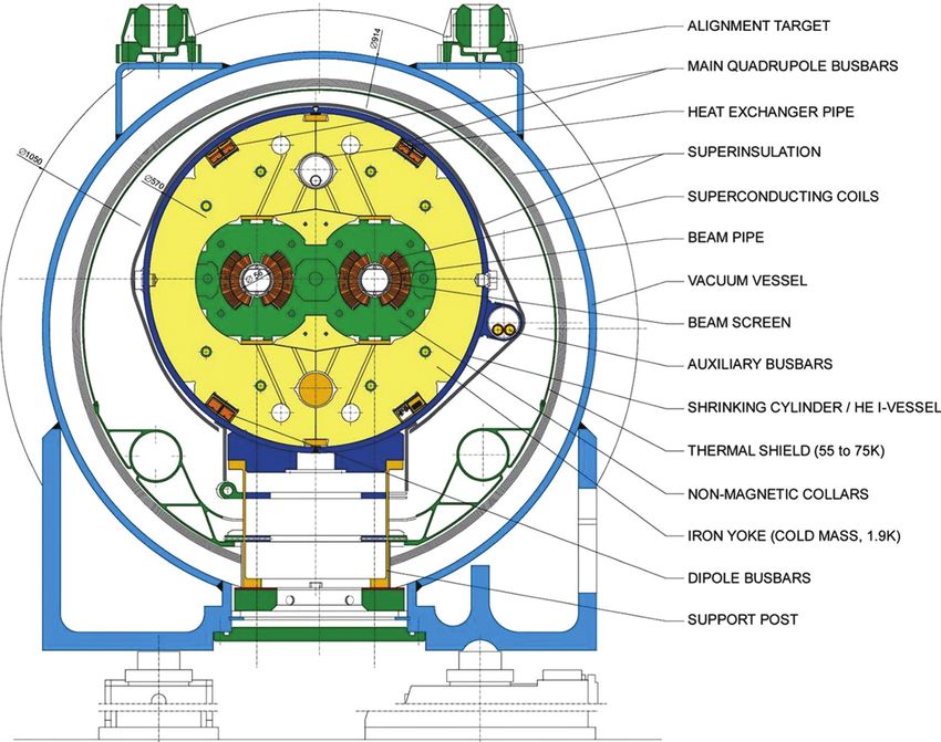
PTEP 2014, 02A102                                                                             L. Evans

Fig. 3. LHC superconductor and cable.

                                                                                                          Downloaded from http://ptep.oxfordjournals.org/ by guest on September 25, 2015
Fig. 4. The regular lattice.

co-extrusion of Nb-Ti ingots with copper rods and cans. The strands and multi-strand cable are shown
in Fig. 3.
  It is of interest to make the dipoles as long as possible to reduce the number of units and inter-
connects, and therefore the cost, and also to maximize the filling factor, reducing the magnetic field
required for a given energy. A number of practical factors, including the road transport of magnets
and facility of installation, put an upper limit on their length. The final magnets have a magnetic
length of 14.3 m with a physical length of 15 m. The regular lattice period is 106.9 m with six dipoles
and two 3 m-long quadrupoles per period (Fig. 4). The ends of the dipoles contain the small octupole
and decapole correctors to control unwanted multipoles in the dipoles, especially in the “snapback”
regime at the start of acceleration when persistent currents cause strong nonlinearities.
  In addition to these small correctors, each lattice period contains a sextupole to correct the chro-
maticity, as well as a dipole for orbit correction. Depending on its location in the machine, each
period contains an additional corrector, either a trim or skew quadrupole or a Landau octupole.
  The mechanical forces in the dipole are very large, up to 300 tons/meter pushing the coils outwards
at full power. These forces are contained by strong non-magnetic steel collars surrounded by an iron
yoke and stainless steel cylinder.
  Series production of dipoles and quadrupoles has been a monumental task. All superconducting
cable and many mechanical components were supplied to the cold mass assemblers (three for the
dipoles and one for the quadrupoles) by CERN in order to ensure uniformity of production and also
to allow control of the distribution of contracts between countries. The cold masses were assembled

                                                 6/20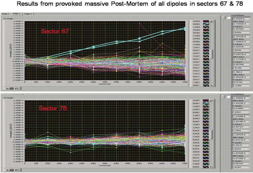
PTEP 2014, 02A102                                                                               L. Evans

Fig. 5. Schematic of LHC magnet cooling scheme.

into their cryostats at CERN. All magnets were tested at 1.9 K before installation in the tunnel. From
start to finish, production, from cable to fully tested magnets, took about six years.
   The total mass to be cooled to 1.9 K is 37,000 tons, requiring approximately 80 tons of superfluid

                                                                                                            Downloaded from http://ptep.oxfordjournals.org/ by guest on September 25, 2015
helium to be maintained at 1.9 K during the entire period of operation. The main reason for operating
in superfluid is to extend the operating range of the Nb-Ti superconductor. However, operating below
the lambda point brings its own advantages and challenges. The rapid drop in the specific heat of the
conductor at low temperature makes it imperative to use the special properties of superfluid helium
in the best possible way. The insulation between turns in the coil has been designed to be porous so
that, with its low viscosity, the helium can permeate the windings where it buffers thermal transients
thanks to its high specific heat (2000 times that of the conductor per unit volume). The excellent
thermal conductivity of the fluid (peaking at 1.9 K and typically 1000 times that of OFHC copper)
enables it to conduct heat without mass transport with no need for fluid circulation or pumps.
   The magnets operate in a static bath of superfluid at atmospheric pressure using an unconven-
tional cooling scheme. The bath is continuously cooled through a linear heat exchanger made out of
cryogenic-grade copper and extending the full 107 m length of each cell (Fig. 5). The pressure inside
the heat exchanger is 15 mbar. Helium expanded into the tube through a Joule–Thomson valve is
cooled to 1.8 K. The static helium in the magnets is then cooled by latent heat of vaporization of
the small quantity of superfluid inside the heat exchanger. This scheme has been shown to work
beautifully, keeping the LHC temperature stable for weeks on end.
   At 7 TeV, even protons start to produce synchrotron radiation. The power emitted is about 4 kW
per beam, which is much too low to provide useful synchrotron radiation damping, but is quite a
nuisance since it must be absorbed on the cold surface of the beam pipe. One Watt at 1.9 K corre-
sponds to a kilowatt at room temperature, which cannot be accepted by the refrigerators. Therefore
the beam vacuum chamber contains a liner cooled to 20 K in order to intercept the heat load with
better thermodynamic efficiency.

4.   Machine layout
In parallel with the approval of the LHC machine, proposals for the experimental program were
being examined by the LHC Experiments Committee (LHCC), whose job it was to give advice to the
CERN management and through it to Council. Unlike the machine, the detectors have considerable
independence. Only 20% of their funding comes through CERN. The rest comes from collaborating
institutes all around the globe. However, it is the responsibility of CERN to provide the infrastructure,
including the caverns in which the experiments are housed. Eventually, the LHCC proposed approval

                                                  7/20
PTEP 2014, 02A102 L. Evans
Downloaded from http://ptep.oxfordjournals.org/ by guest on September 25, 2015
Fig. 6. Excavation of ATLAS. The cavern is the largest ever built in the type of rock encountered in the Geneva
basin.
of two large general-purpose detectors, ATLAS and CMS, as well as two smaller more specialized
detectors, ALICE for heavy-ion physics and LHCb for the study of matter–antimatter asymmetry.
4.1. Civil engineering
The first job was to decide where these detectors were to be located. The LHC ring is segmented into
eight identical arcs joined by eight 500 m Long Straight Sections (LSS) labeled from 1 to 8. Four
of these LSS (at Point 2, 4, 6 and 8) already contain experimental caverns in which the four LEP
detectors were located. These caverns are big enough to house the two smaller experiments. ATLAS
and CMS required much bigger caverns, where excavation had to start while LEP was still running,
the four even points therefore being excluded. Point 3 lies in a very inhospitable location deep under
the Jura Mountains, and for various reasons Point 7 could also be excluded. There remained Point 1,
conveniently situated opposite the CERN main campus and diametrically opposite Point 5, the most
remote of all. Needless to say, there was considerable pressure from both ATLAS and CMS collabo-
rations to get the more convenient Point 1. In the end, geology prevailed. Sample borings showed that
Point 1 was much better suited for the larger cavern required for ATLAS (Fig. 6). CMS was allocated
Point 5. ALICE re-used the large electromagnet of one of the old LEP experiments at Point 2 and
LHCb was assigned the cavern at Point 8.
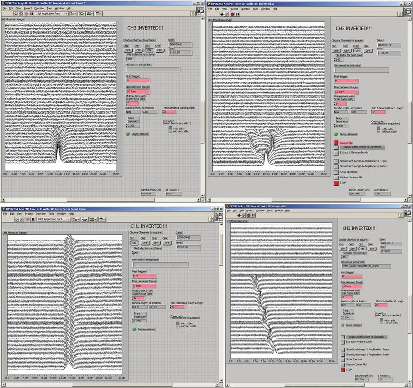
The excavation of the large caverns at Points 1 and 5 posed different problems. At Point 1, the
cavern is the largest ever excavated in such ground conditions. The work also had to continue whilst
the LEP machine was still operating. At Point 5, although the exploratory borings showed that there
was a lot of ground water to be traversed when sinking the shaft, the speed of water flow took us by
surprise. Extensive ground freezing was necessary to produce an ice wall around the shaft excavation
(Fig. 7).
An additional complication at Point 5 was that during the preparation of the worksite, the founda-
tions of an ancient Roman farm (4th century ad) were discovered. Work was immediately stopped so
8/20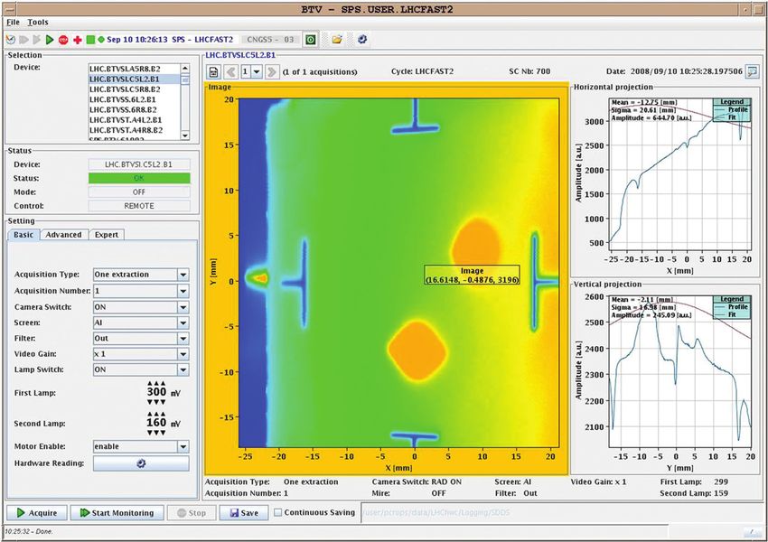
PTEP 2014, 02A102                                                                                  L. Evans

                                                                                                               Downloaded from http://ptep.oxfordjournals.org/ by guest on September 25, 2015
Fig. 7. An underground river made the excavation of the shaft of the CMS cavern very difficult. A ring of
pipes carrying liquid nitrogen was used to form a wall of ice inside which the shaft was excavated and lined
with concrete.

Fig. 8. Roman coins found during archeological excavations at Point 5. The larger coins are from the Emperor
Maxence minted in Ostia between 309 and 312 ad. The smaller coins are from the Emperor Constantin minted
in London and Lyon between 313 and 315.

that the mandatory archeological investigation could be made. Articles of jewelry and coins minted
in London, Lyon and Ostia, the ancient harbor city 35 km south-west of Rome, were found (Fig. 8).
The coins minted in London were dated 309–312 ad. One striking feature, easily seen from the air
(Fig. 9), is the precise alignment of the villa with respect to the boundaries of the present-day fields.
This is evidence that the “cadastre”, or land registry of today, is derived from the time of the Roman
occupation.

                                                   9/20
PTEP 2014, 02A102                                                                                   L. Evans

                                                                                                                Downloaded from http://ptep.oxfordjournals.org/ by guest on September 25, 2015
Fig. 9. Aerial view of Point 5 in 1998. In the bottom of the picture are the original buildings from LEP. The
foundations of a Roman farm from the 4th century can be seen top-centre. Note how its walls are aligned
perfectly with the boundaries of the surrounding fields.

  A third civil engineering work package was the construction of two 2.6 km-long tunnels connecting
the Super Proton Synchrotron (SPS) to the LHC and the two beam-dump tunnels and caverns.

4.2.   Machine utilities
It takes more than just magnets to make a particle accelerator. Once the four straight sections were
allocated to the detectors, the other four could be assigned to the essential machine utilities.
   Figure 10 shows a schematic layout of the LHC ring. The two beams cross from one ring to the other
at the four collision Points 1, 2, 5 and 8; elsewhere, they travel in separate vacuum chambers. They
are transported from the SPS through two 2.6 km-long tunnels. Due to the orientation of the SPS with
respect to the LHC, these tunnels join the LHC ring at Points 2 and 8. It was therefore necessary to
integrate the injection systems for the two beams into the straight sections of the ALICE and LHCb
detectors.
   Clockwise from Point 2, the LSS at Point 3 lies deep below the Jura Mountains. It contains no
experimental cavern from the LEP days and, moreover, it is known from the experience of excavat-
ing the LEP tunnel that the geological conditions in this region are very bad. Cracks and fissures in
the rock allow water to percolate from the very top of the mountain above, more than 1000 m high,
producing a large static water pressure. In view of this it was decided that no additional civil engi-
neering for tunnel enlargement would be allowed in this region. It was therefore assigned to one of
the two collimation systems, which could be fitted into the existing tunnel.
   Collimation is essential in a collider. As the beams are stored for many hours, a halo of parti-
cles slowly builds up around the core, mainly due to nonlinearities in the magnetic field or by the
interaction of one beam with the other (in a lepton machine this halo would be damped by syn-
chrotron radiation). If it were left uncontrolled, eventually particles would hit the vacuum chamber
wall, producing unacceptable background in the detectors and risking a quench (a transition from the
superconducting state due to the accompanying temperature rise) in some of the magnets. Collima-
tors are specially designed motorized blocks that can be driven into the machine aperture to “clean”

                                                   10/20
PTEP 2014, 02A102 L. Evans
Downloaded from http://ptep.oxfordjournals.org/ by guest on September 25, 2015
Fig. 10. Schematic machine layout.
the beam by removing the halo locally. The collimators constitute the primary aperture restric-
tion in the machine. When they are at their operating positions, the machine aperture is just a few
millimeters.
Point 4 is assigned to the all-important Radio Frequency (RF) acceleration system (Fig. 11). Accel-
eration is obtained by a longitudinal oscillating electric field at a frequency of 400 MHz in a set of
resonant cavities. The electric field in the cavities is very high, in excess of five million volts per
meter. Once again, superconductivity comes to the rescue. The cavities are made of copper but there
is a thin film of niobium deposited on the inside surface. When cooled with liquid helium, this film
becomes superconducting, enabling currents to flow in the cavity walls without loss.
Each revolution, the beam is given a small increase in energy as long as the field is pointing in the
right direction. To achieve this, the frequency of the RF must be a precise harmonic of the revolution
frequency so that each time a particle comes around, the field is pointing in the same direction.
As the energy slowly increases, the magnetic field must also rise to keep the beams in the center
of the vacuum chamber since the magnetic field required to bend a particle on a constant radius is
proportional to its energy. The RF system needs considerable infrastructure and profits fully from
the space available in the old LEP cavern at Point 4.
11/20PTEP 2014, 02A102 L. Evans
Downloaded from http://ptep.oxfordjournals.org/ by guest on September 25, 2015
Fig. 11. The superconducting Radio Frequency cavities at Point 4.
At 7 TeV with nominal intensity, the stored energy in one of the beams is 350 MJ, equivalent to more
than 80 kg of TNT. If, for any reason, this beam is lost in an uncontrolled way, it can do considerable
damage to machine components, resulting in months of down-time. It is therefore essential to have a
system that can reliably extract the beams very quickly and deposit them on special absorber blocks.
This “beam-dump” system is located at Point 6. A set of special magnets can be pulsed very rapidly to
kick the whole beam out of the machine in a single turn. The extracted beams are transported 700 m in
an evacuated pipe and deposited on absorber blocks specially designed to take the enormous power.
The beam dump can be triggered by many sources, for instance if an excessive beam loss on the
collimators is detected or if a critical power supply fails. It is also used routinely during operation;
when the intensity in the beams falls too low, the beams are “dumped” by the operators in order to
prepare the machine for the next filling cycle.
Finally, Point 7, like Point 3, contains a second collimation system.
The LSS each side of the four detectors house the equipment needed to bring the beams together
into a single vacuum chamber and to focus them to a small spot with a radius of about 15 µm at the
collision points inside the detectors (Fig. 12). This requires special elements and is a prime example
of international collaboration in the machine construction. The superconducting magnets required to
focus the beams where built in the USA and Japan, with the Japanese magnets shipped to the USA
for integration into their cryostats before delivery to CERN. The special dipoles used to bring the
two beams to the same orbit were built in Brookhaven in the USA, and the current-feed boxes for all
superconducting elements in the straight sections come from FERMILAB. Other equipment in the
LSS comes from India and Russia.
5. First commissioning
By 10 September 2008, seven of the eight sectors had been successfully commissioned to 5.5 TeV
in preparation for a run at 5 TeV. Due to lack of time, the eighth sector had only been taken to 4 TeV.
Beam commissioning started by threading beam 2, the counter-clockwise beam around the ring,
12/20PTEP 2014, 02A102 L. Evans
Downloaded from http://ptep.oxfordjournals.org/ by guest on September 25, 2015
Fig. 12. The “inner triplet” in the LSS left of Point 1 (ATLAS). The orange cryostats contain quadrupole
magnets which focus the beams to a 30 µm spot at the interaction point.
Fig. 13. Beam on turns 1 and 2.
stopping it at each LSS sequentially in order to correct the trajectory. In less than an hour the beam had
completed a full turn, witnessed by a second spot on a fluorescent screen intercepting both injected
and circulating beams (Fig. 13).
Very quickly, a beam circulating for a few hundred turns could be established (Fig. 14). The decay
in intensity is due to the debunching of the beam around the ring since the RF system was not yet
13/20PTEP 2014, 02A102 L. Evans
Downloaded from http://ptep.oxfordjournals.org/ by guest on September 25, 2015
Fig. 14. A few hundred turns.
switched on. Figure 15 shows the RF capture process. Each horizontal line on the mountain range
display records the 2 ns-long bunch intensity every 10 turns from bottom to top. Without the RF the
beam debunches as it should in about 250 turns, or 25 ms. In the next subfigure, the first attempt was
made to capture the beam, but as can be seen, the injection phase was completely wrong. Adjusting
the phase allowed a partial capture, but at a slightly wrong frequency. Finally, adjusting the frequency
resulted in a perfect capture.
The closed orbit could then be corrected. Figure 16 shows the first orbit correction where, remark-
ably at this early stage, the rms orbit is less than 2 mm. It can be seen that in the horizontal plane
the mean orbit is displaced radially by about a millimeter, indicative of an energy mismatch of about
0.9 permil.
6. The accident
Commissioning proceeded rapidly with circulating beam in the other ring until, on 18 September,
a transformer failed at Point 8, taking down the cryogenics in that sector. Since it was impossible
to circulate the beam, attention turned to bringing the last remaining sector up to 5 TeV like the
others. On 19 September, the last remaining circuit was being ramped to full field when, at 5.2 TeV,
a catastrophic rupture of a busbar occurred causing extensive damage in Sector 34. These busbars
are connected by induction brazing with three layers of tin/silver solder in a copper box. Initially it
was foreseen to clamp these busbars mechanically in addition to the solder, but this was discarded on
the grounds that it would increase the hydraulic impedance in the interconnect region and therefore
reduce the effectiveness of conduction cooling in the superfluid helium.
A fact-finding commission was established where it was concluded that the most probable cause
of the accident was too high a resistivity in one of the 10,000 superconducting busbar joints due to
the omission of the solder. In a normal machine this would have caused minor damage. However,
the joint rupture resulted in an arc piercing the helium vessel. The resultant high pressure in the
insulating vacuum and the volume of helium gas was too high for the rupture discs to take, resulting
14/20PTEP 2014, 02A102 L. Evans
Downloaded from http://ptep.oxfordjournals.org/ by guest on September 25, 2015
Fig. 15. Clockwise from top left: No RF, debunching in ∼25 × 10 turns, i.e. roughly 25 ms. First attempt at
capture, at exactly the wrong injection phase. Capture with corrected injection phase but wrong frequency.
Capture with optimum injection phasing, correct reference.
Fig. 16. Corrected closed orbit on B2. Energy offset of ∼ − 0.9 permil due to the capture frequency.
15/20PTEP 2014, 02A102 L. Evans
in overpressure and displacement of magnets off their jacks. In total, 14 quadrupoles and 39 dipoles
needed replacing.
7. The search for further defects
An urgent priority after the accident was to sift through the post mortem data to see if any precursors
of the accident could be detected, in particular any anomalous temperature increase in the affected
area.
Detecting temperature rise in the superfluid helium is made difficult for two reasons. The first is
the enormous thermal conductivity of superfluid helium (Fig. 17). This provides good cooling of
joints initially, but the thermal conductivity is a function of flux density (Fig. 18), so as the heating
increases, the cooling capacity quickly collapses, especially in the region of the splices with high
hydraulic impedance.
Every magnet is equipped with a “post mortem” card containing an analog to digital converter and
Downloaded from http://ptep.oxfordjournals.org/ by guest on September 25, 2015
a buffer memory in order to measure voltages, usually on a trigger due to a quench. It was realized
that these cards could also be used to improve the signal-to-noise ratio in measuring voltages in DC
conditions by averaging, thereby opening up the possibility of making Ohmic measurements across
each splice. Figure 19 shows such measurements of all the joints in the dipole chains of Sectors 67
and 78 during a stepwise current ramp to 5 kA. In Sector 67 there is one anomaly visible with a
resistance of 47 n. It was possible to locate exactly which splice was responsible. Both the 100 n
splice previously mentioned and the 47 n splice were inside magnets which had already been tested
to full current. They have both been removed and the bad splices confirmed. No other such splices
have been detected anywhere else in the machine.
However, during the removal of damaged magnets it was discovered that in some instances, solder
had been leaking out of the interconnect joints during brazing, weakening the joints in the case of
a (very unlikely) busbar quench. Consequently it has been decided to operate the LHC at reduced
energy until additional consolidation can be made during a shutdown. This consolidation will consist
of strengthening the interconnects, increasing the number of rupture discs in sectors where it has not
already been done and reinforcing the jacks at the vacuum barriers so that they can take higher
differential pressure in case of a very unlikely further incident of this kind.
Fig. 17. Equivalent thermal conductivity of He II.
16/20PTEP 2014, 02A102 L. Evans
Downloaded from http://ptep.oxfordjournals.org/ by guest on September 25, 2015
Fig. 18. Effective thermal conductivity of He II as a function of flux density.
Fig. 19. Snapshots in S67 and S78 on all 154 dipoles – B32.R6 with a high (47 n) joint resistance between
the poles of one aperture (top trace).
8. Recommissioning
The repairs and hardware recommissioning took until November 2009. In the short time available
until the end of the year, beams were accelerated to an energy of 1.18 TeV, equivalent to a dipole field
of 2 kA, and a small amount of physics data taking was done. On 30 March 2010, first collisions
were obtained at a center-of-mass energy of 7 TeV. Since then, operating time has been split between
machine studies and physics data taking.
In view of the very large stored energy in the beams, particular attention has to be given to the
machine protection and collimation systems. More than 120 collimators are arranged in a hierarchy of
17/20PTEP 2014, 02A102 L. Evans
Fig. 20. Orbit feedback in operation.
Downloaded from http://ptep.oxfordjournals.org/ by guest on September 25, 2015
Fig. 21. Loss maps for collimation.
primary, secondary, and tertiary collimators. Tight control of the orbits in the region of the collimators
is achieved with a feedback system. Figure 20 shows orbit feedback in operation during the ramp.
The three plots show the mean, rms orbit distortion, and momentum deviation during the ramp. The
maximum rms orbit deviation is 0.08 mm.
The collimation system also works very efficiently. Figure 21 shows a loss map around the ring
obtained by provoking beam loss. The losses are located precisely where they should be, with a
factor of 10,000 difference between the losses on the collimators and those in the cold regions of the
machine.
9. Operation
The machine performance at this early stage is very impressive [10]. Single beam lifetime of more
than 1000 hours has been observed, an order of magnitude better than expected, proving that the
vacuum is considerably better than expected and also that the noise level in the RF system is very low.
The first run for physics started in 2010 at 3.5 TeV per beam with 248 bunches per beam and a
maximum luminosity of 1032 cm−2 s−1 . The integrated luminosity for the year was 50 pb−1 .
18/20PTEP 2014, 02A102 L. Evans
Downloaded from http://ptep.oxfordjournals.org/ by guest on September 25, 2015
Fig. 22. Integrated luminosity in all four detectors in 2012.
In the second year of operation in 2011, still at 3.5 GeV, the number of bunches per beam was
increased to 1380 and the peak luminosity increased to 3.7 × 1033 cm−2 s−1 . The integrated lumi-
nosity in ATLAS and CMS was 5.6 fb−1 , enough to give the first hint of a signal of the Higgs
boson.
In 2012, the energy was increased to 4 TeV and the number of bunches per beam to 1380, with a
bunch separation of 50 ns. The peak luminosity reached 7.7 × 1033 cm−2 s−1 , which is 30% higher
than the design luminosity at this energy. By the time of the summer conferences a further 6.7 fb−1
was accumulated, enough to confirm the existence of a new boson, announced in a seminar at CERN
on 4 July 2012. By the end of the year a total integrated luminosity of 23.3 fb−1 was accumulated in
both ATLAS and CMS (Fig. 22), enough to measure the spin of the new particle and to confirm that
it is indeed the Higgs boson.
The versatility of the machine has been amply demonstrated. In addition to the proton operation,
dedicated runs have been made with heavy ion (Pb–Pb) collisions and even a run with lead on protons,
a tricky procedure since the two beams must rotate on different orbits in order to have the same
revolution frequency.
After a spectacular start, the LHC is now in a two-year shutdown for consolidation of the machine
and detectors. When it comes back on in 2015 it will be able to operate at its full design energy of
7 TeV.
Acknowledgements
The LHC is the most complex scientific instrument ever constructed. It has taken 15 years to build and many
problems have been encountered on the way. These have all been overcome thanks to the resourcefulness and
resilience of the people who built it, both inside CERN and in our collaborating laboratories around the world.
The commissioning and operation of the machine has been nothing short of spectacular, a tribute to the quality
of its design and to the competence of the people responsible for its exploitation.
References
[1] O. S. Brüning, P. Collier, P. Lebrun, S. Myers, R. Ostojic, J. Poole, and P. Proudlock (eds), LHC Design
Report. Vol. 1: The LHC Main Ring, CERN-2004-003 (CERN, Geneva, 2004).
19/20PTEP 2014, 02A102 L. Evans
[2] L. Evans (ed.), The Large Hadron Collider: A Marvel of Technology (EPFL Press, Lausanne, 2009).
[3] S Wojcicki, Rev. Accl. Sci. Technol. 01, 295 (2008).
[4] S Wojcicki, Rev. Accl. Sci. Technol. 02, 265 (2009).
[5] The Large Hadron Collider and the Long-Term Scientific Programme of CERN: Executive Summary,
CERN/SPC/679, CERN/CC/2016 (CERN, Geneva, 1993).
[6] United States Department of Energy, High Energy Physics Advisory Panel’s Subpanel on Vision for the
Future of High Energy Physics, DOE/ER-0614P (United States Department of Energy, Washington
DC, 1994).
[7] CERN, Hundredth Session of the Council. First Part, CERN/2052, 24 June 1994 (CERN, Geneva,
1994).
[8] CERN, Hundredth Session of the CERN Council. Second Part, Resolution Approval of the Large
Hadron Collider (LHC) Project, CERN/2075, 15 December 1994 (CERN, Geneva, 1994).
[9] United States Department of Energy, Department of Energy Assessment of the Large Hadron Collider,
DOE/ER-0677 (United States Department of Energy, Washington DC, 1996).
[10] M. Lamont, Proc. 4th Int. Particle Accelerator Conf., Shanghai, p. 6 (2013).
Downloaded from http://ptep.oxfordjournals.org/ by guest on September 25, 2015
20/20You can also read