Self-Assembly of a Swarm of Autonomous Boats into Floating Structures
←
→
Page content transcription
If your browser does not render page correctly, please read the page content below
Self-Assembly of a Swarm of Autonomous Boats
into Floating Structures
Ian O’Hara, James Paulos, Jay Davey, Nick Eckenstein, Neel Doshi, Tarik Tosun, Jonathan Greco,
Jungwon Seo, Matt Turpin, Vijay Kumar and Mark Yim
Abstract— This paper addresses the self-assembly of a large decades, and there are a variety of approaches [2], [3]. How-
team of autonomous boats into floating platforms. We describe ever, the unique geometric and environmental constraints of
the design of individual boats, the systems concept, the al- this system require a new planner.
gorithms, the software architecture and experimental results
with prototypes that are 1:12 scale realizations of modified Modular sea bases were examined in [4] as a potential
ISO shipping containers, with the goal of demonstrating self- way to build Mobile Offshore Bases focusing on a large
assembly into large maritime structures such as air strips, seaport or air base afloat at sea and movable under its own
bridges, harbors or sea bases. Each container is a robotic power. These systems could create bases where none exist
module capable of holonomic motion that can dock in a which could be particularly useful for rapidly developing
brick pattern to form arbitrary shapes. Over 60 modules
were built of varying capability. The docking mechanism is events. The modules were relatively large; in one version,
designed to be robust to large disturbances that can be expected the modules were 280 m long and they proposed assembling
in the high seas. The docking mechanism also incorporates five of them end to end to form a landing strip. As in this
adjustable stiffness so that the conglomerate can comply to paper, a scale model was constructed and examined, though
waves representative of sea state three, and have the ability to at 1:150 scale and tethered [5]. They tested three modules
dynamically stiffen as required. The component modules for
autonomous assembly, docking and simultaneous collision-free that formed a chain, but did not have to deal with assembly
planning as well as the software architecture are presented of larger numbers of modules into complex shapes.
along with the description of experimental verification.
II. S YSTEM A RCHITECTURE
I. I NTRODUCTION At the highest level, the system is split into three compo-
Large robotic self-assembled aquatic structures enable nents: a fleet of boats, a central computer, and a poolside
capabilities such as the formation of offshore bases for hu- camera array (see Fig. 1). The fleet of boats consists of
manitarian aide to hurricane stricken islands, ad hoc landing independent actors which are unaware of the others and are
strips, encircling oil spills, or refueling depots in the middle responsible for fulfilling requests from the central computer.
of the ocean [1]. A large number of modified standard ISO The central computer consists of a number of loosely coupled
shipping containers, which conform to a standard, low cost software components which, working together, are responsi-
form factor easily transported around the world, can be used ble for taking an assembly blueprint and giving orders to the
to form a swarm of autonomous boats that could be used boats to assemble the specified conglomerate. Finally, the
to join together to form Modular Sea Bases (MSB) which camera array provides boat pose feedback for all boats to
can in turn be delivered nearly anywhere on the planet that the central computer and the boats themselves.
container ships can reach. This paper first describes the implemented hardware de-
This work describes the design of individual boats, the sign. It then goes on to describe a software system capable of
systems concept, the algorithms, the control and planning both controlling the boats and assembling the conglomerates
software and the software architecture of working with up autonomously from a blueprint. Next, to address concerns
to 60 modules at 1:12 scale. We will use the term module or about the destructive effects of a varying sea environment,
boat to refer to the modified containers. With such large analysis is done on conglomerate dynamics and on the
numbers, there are questions of how the modules self- docking mechanism of the boats. Finally, experiments in a
organize, plan and execute motions that avoid collisions, pool are described that verify system capabilities.
while achieving the goal conglomerate shape (e.g. a harbor
that conforms to the shoreline or a floating landing strip). III. H ARDWARE
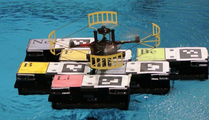
Self-assembly of autonomous agents (mobile agents dock- 1) Propulsion: Each shipping container in the full-sized
ing with each other) has been a research problem in the system is capable of holonomic motion. Our scaled system
self-reconfigurable robot research community for nearly two modules produce holonomic motion using four thrusters
positioned in the corners of each scaled shipping container.
This work was sponsored in part by the Defense Advanced Research Each thruster uses a ‘water wheel’ style design consisting
Projects Agency and ONR Grant N00014-09-1-1031. The views expressed of a spinning paddle and a water guide that produces a jet
are those of the authors and do not reflect the official policy or position of
the government. of water in one of two fixed directions (see Fig. 2). Boats
Authors are with the GRASP Lab. and Dept. of Mechanical Engineering capable of holonomic motion eases trajectory following and
and Applied Mechanics, Univ. of Pennsylvania, Philadelphia, PA, USA. performing docking maneuvers. Making fine maneuvers with
ianohara@gmail and {jpaulos, jaydavey, neck,
neeld, ttosun, jongreco, juse, mturpin, yim, the boats also enables more precise station keeping against
kumar}@seas.upenn.edu currents, waves or wind effects.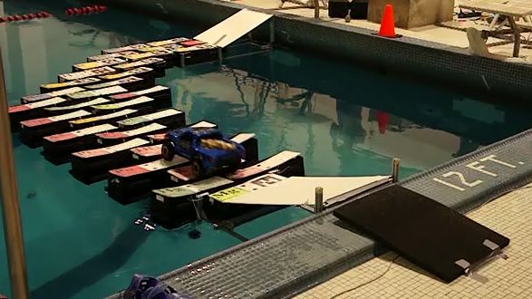
Poolside Camera Array                       Central Computer

                                                                       Assembly
    Vision Laptop        Vision Laptop         Homography
                                                                       Blueprint
          1                    N

      Camera                 Camera
                                                 Coordinator
               Fleet of Boats                                          Assembly
                                                                        Planner
                                   Boat            Docker
    Boat
                      Boat
                                                                       Trajectory
                                                Distributor
                                                                        Planner
       Boat
                                Boat
                                           Component
                                             Types   ROS      Custom Process    Text File

Fig. 1: System components are physically distributed across                                               (a) Female                    (b) Male
a central computer, vision laptops, and independent boats                                   Fig. 3: Docking mechanisms. (a) Loop detail fully extended,
           Male docking                                                                     (b) Hook detail showing sweep.
           geometry            Hook
                                                                              Loop
                                                                                              When docked, the interface between two modules includes
                                                                                           padding on the sides of the hull. This padding lets structures
                                                                                           made from the floating modules flex which is important to

                                                                                            survive rough sea conditions as explained in Sec.V-B. The
                                          Female docking
                                          geometry                                          winches in the female side of the docking mechanism can
                                                                                            pull two modules tighter, squeezing the padding to provide
                                            Padding
                                                                                            a controlled stiffness between modules.
                                                                                               3) Stability: Our scaled system modules were built with
                                                                                            many components sitting well above the hull bottom result-
                                                                                            ing in a high center of mass. The boats also have low density
           Thruster                                                                         resulting in a large freeboard. This combination makes the
                    Bulb keel                                                               modules prone to large pitch and roll motions with the
                                                                                            possibility of overturning. In addition, large roll and pitch
                                                                                            introduce errors in the localization when using overhead
                                                                                            cameras. For these reasons the scaled modules were given a
 Fig. 2: Tactically Expandable Maritime Platform module                                     bulb keel to keep the modules upright and resistant to roll.
                                                                                            This bottom feature is likely not needed on the full sized
                                                                                            boats, which will have a much lower freeboard height.
   2) Docking: The implemented docking concept was con-
ceived by General Dynamics and QinetiqNA who con-                                              4) Electrical Design: All of the electronics on an indi-
structed the full-sized ISO container prototype. It is a male                               vidual boat are controlled by a Linux compatible Gumstix
to female connection mechanism for connecting modules                                       computer-on-module [7], which is mounted on a custom
together under dynamic wave conditions. One long side of                                    breakout board. The Gumstix was chosen for its size and
the module is a male side and the opposing long side is a                                   to take advantage the Linux infrastructure (networking, de-
female side. The male side includes a hook sweeping in the                                  velopment tool chain, drivers, etc). Using Linux also al-
horizontal plane that catches a suspended vertical cable on                                 lowed easy integration with ROS [8]. The Gumstix controls
the female side of another module. Spring loaded folding                                    two motors with built-in encoders to actuate the winches
arms (female side) are used to hold out a loop of string for                                (Fig. 3a), two analog servos to move the hooks (Fig. 3b),
the hook to catch. A motor winches both ends of the string at                               and four motors used for propulsion of the boat. All six
once on a spiraled winch drum (Fig. 3a) to allow the spring                                 motors are controlled using off-the-shelf high current drivers,
loaded arms to move out at the same time and at a non-                                      and are connected to the main processor with TTL serial. A
linear speed during the docking process (outlined in Sec.IV-                                bidirectional voltage translation board is necessary for the
D). Additionally, if modules in the scaled system are located                               Gumstix (at 1.8 V logic) to send and receive control signals
in the docked position, but the docking mechanisms are not                                  to all actuators (at 3.3 V and 5 V logic). A central PCB
engaged, the modules can still dock. A constant force spring                                connects the Gumstix, all of the actuators, a leak sensor, and
located in the hook allows the hook mechanism to comply                                     an externally visible LED board together and routes power
in the situations where the sweeping hook interferes with a                                 to them from NiMH batteries.
close neighboring module.
                                                                                                                   IV. S OFTWARE
   Note that this docking mechanism results in a brick wall
pattern as can be seen in Figs. 11, 12. Although the mech-                                     The overall control architecture required for autonomous
anism does not allow short-end to short-end attachments,                                    operation spans multiple software components and multiple
general 2D shapes can be constructed [6]. An algorithm that                                 physical platforms. At the highest level, the Coordinator
plans for the assembly sequence for a given goal shape is                                   is responsible for sequencing operation of the Assembly
described in Sec. IV-B.                                                                     Planner, the Trajectory Planner, and the Docking Routine.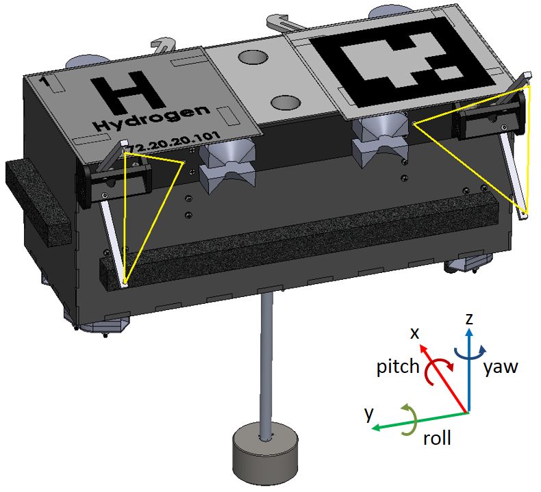
3
               Start

                                                                                                         2
                                                                                                             3       5                           2         4
                                             Coordinator
     Set seed boat state to
            docked                                                                                       0       4
                                                                                                                                                      0        5
                                         Dock
                                                                                                             1
                                       Sequence
                                                                                                                                  (a)
     For each boat:
                                                                                                                                                           1
           If boat.state = ...
                                     Boat          Boat
                                    Object        Object          Assembly
                      free
                                                                   Planner
                                                                                                                         2
                 docking                                                                                                     3          5
                                                              Filled          New
                                                               Dock           Dock
                                                                             Points
                                                                                                                         0        4
                  docked
                                                              Points                                                                                  T5
                                                                                                                                                 S5
                                      Send docked boats to                                                                         C0       C5
                                      Assembly Planner,
                                        await response                                                                           S0
                                                                                                                             T0
                Replan        yes       Associate targets                                                                         (b)
               Needed?                  with dock points          Trajectory
                                                                   Planner                   Fig. 5: (a) A shape with six sites (left), and its assem-
    no
                                       Send world state                                      bly sequence (right). (b) One state in the assembly where
               All Boats                to Trajectory                         Trajectories
               Docked?                     Planner
                                                             Free Boats,
                                                             Obstacles,
                                                                                             boat.state (Fig. 4) is free, docking, and docked for
                                                               Targets
                                                                                             the blue, red, and black boats, resp. The red boat has reached
         yes
                                                                           Boats             T0 , target point of site 0, and has just changed to docking.
                Done

                       Fig. 4: Coordinator Operation                                         B. Assembly Planner

These components reside physically within a central com-                                        The Assembly Planner parses a blueprint for the desired
puter, as sketched previously in Fig. 1. Each boat is a semi-                                configuration and generates an assembly sequence that spec-
independent agent which responds to infrequent trajectory                                    ifies an order for filling the dock sites. The sequence can
commands and rapid pose estimates. A full scale field                                        be executed interactively as mentioned in Sec. IV-A: the
deployment might utilize radio for communication and GPS                                     Assembly Planner takes as input, the shape of the current
for localization. In our experiments a local wifi network                                    structure and returns open dock sites that can be occupied
provides communication managed by a Distributor Node, and                                    around the current structure. The algorithm [6] is briefly
overhead cameras publish pose estimates.                                                     summarized here. First, a goal shape is represented as a
                                                                                             single connected collection of dock sites to be occupied by
A. Coordinator                                                                               boats (the left panel of Fig. 5a). After arbitrarily designating
                                                                                             one of the dock sites as a seed, dock site 3 in this example,
    The Coordinator, outlined in Fig. 4, is an event-based                                   we construct a directed graph on the collection of the
state machine that allows the Assembly Planner, Trajectory                                   dock sites such that its edges represent local-scale assembly
Planner, and Docker to operate with some degree of asyn-                                     precedences (the right panel of Fig. 5a). The resultant graph
chrony. The Coordinator parses a blueprint for the desired                                   is guaranteed to be acyclic; we then obtain an assembly
configuration and stores an internal map of dock sites,                                      sequence that can be executed without infeasible, cyclic
boat locations within the desired conglomerate (see the left                                 dependency. As a result, the structure grows as a single
panel of Fig. 5a). As construction progresses, the Assembly                                  connected component from the boat occupying the seed with
Planner identifies open dock sites that may be simultaneously                                multiple boats docking in a parallel distributed manner. For
filled and that will not later block the assembly sequence.                                  example, at the instant shown in Fig. 5b where dock sites
Near each available dock site the Coordinator assigns a                                      3, 2, and 4 are occupied, free boats can occupy dock sites 0
target point, a global coordinate where the centroid of a boat                               and 5 without mutual communication. Filling the dock sites
should be driven in preparation for docking (see Fig. 5b).                                   is independent according to the assembly sequence shown in
The Coordinator passes the current locations of free boats,                                  the right panel of Fig. 5a. Moreover, following the resultant
target points, and static obstacles to the Trajectory Planner,                               sequence guarantees reachability: there exists a feasible path
which then computes paths for free boats to reach the                                        into any open dock site that is not blocked by the structure.
target points. Whenever a boat reaches a target point, the                                   For example, consider a structure composed of dock sites
Coordinator passes control to the reactive Docking Sequence                                  0, 1, and 3 in the example; to occupy dock site 4, a boat
which maneuvers the boat into the corresponding dock                                         has to pass through the narrow corridor between the boats
site by actuating the hooks and winches to complete the                                      occupying dock sites 3 and 1. The algorithm avoids such
dock. Whenever a dock site is successfully occupied, the                                     difficult to maneuver configurations. The time complexity of
Coordinator notifies the Assembly Planner so that it may                                     the algorithm is O(m2 ) where m is the number of the dock
expose more dock sites for continued assembly.                                               sites of a given goal shape.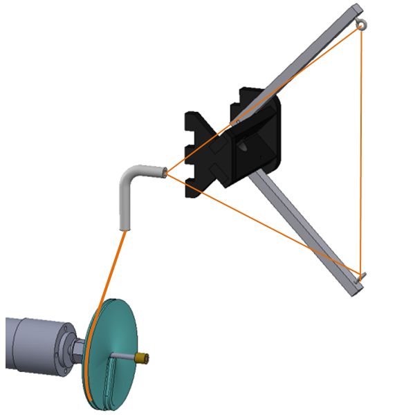
C. Trajectory Planner                                              different starting position and executes the sequence again.
   The Trajectory Planner is responsible for planning paths        This changes the boat’s approach vector and provides an
for free boats to reach the target point for open dock sites.      additional chance for a successful dock.
In this way it provides the logical interface between the high
                                                                   E. Localization System
level discrete reasoning of the Coordinator and the low level
feedback controller embedded on the boats. A plan request             Sensing boat poses is done using APRIL Tags [10] via
from the Coordinator specifies the current locations of free       the cv2cg package [11]. Fiducial markers are placed on each
boats, target points, and static obstacles as inputs to the        boat, and are sensed by one or more cameras located above
planner. The Trajectory Planner then assigns free boats to         the pool surface. These cameras are mounted to a frame
specific target points and generates collision-free trajectories   3.7 m above the pool and 1.0 m out. The viewing frustum
for the boats to reach their respective target points (Fig. 5b).   sees boats in a 12.8 m by 3.7 m rectangle that spans the entire
Globally optimal plans are generated through our determinis-       width of the pool resulting in approximately 2 cm precision.
tic algorithm presented in [9]. Solution paths lay on a visibil-      Each camera is attached via USB to a dedicated laptop
ity graph constructed over the static obstacles, providing a       running cv2cg and gives pose information for each boat’s
fixed margin against collision. The time-dependent motion          tags at 20-30 Hz. These laptops transmit the tag poses in
along these paths further ensures no collisions between            their respective camera frames via UDP to the central com-
moving boats by construction. Planning for ten boats is            puter. The central computer then uses prerecorded calibration
completed in less than one second, and those plans are then        information to project these coordinates into the single pool
published as messages to the Distributor Node, which in            frame coordinate system, generating the (x,y,θ) coordinates
turn sends individual trajectories to each boat. Replanning        for each boat. These world coordinates are then published
is required only when a boat successfully occupies a dock          over the ROS framework for the system components to use.
site, which results in the change of the current structure and
the discovery of new docking sites by the Assembly Planner.        F. System Administration and Networking
The discrete nature of event-triggered plan requests and the          Developing the Coordinator, Trajectory Planner, Assembly
capability of the boats to execute their assigned trajectories     Planner, and code on dozens of floating boats is challenging.
unattended significantly reduces the communication between         To do this, each boat automatically connects to known system
the Coordinator and the many boats.                                wifi networks. Code development occurs on local machines,
D. Docking Routine                                                 using a series of bash scripts that utilize rsync, ssh pipes, and
                                                                   tmux [12] sessions running on the boats to compile, run, and
   When the Coordinator observes that a boat has reached           debug code simultaneously on all of the boats, the central
its target point, control of the boat is passed to the Docking     computer, and the vision laptops. For boats that contain up
Routine. The Docking Routine resides within the Coor-              to date binaries, turning on their power switch is enough for
dinator node and executes a tuned sequence of actions              them to start their ROS node and become fully functional
to bring the boats from the dock ready state to the                within the system.
successfully docked state. There are four stages to                   Most of the system utilizes ROS for both p2p networking
the docking sequence. (1) Starting from the target point           setup and data serialization/deserialization (see Fig.1). ROS
(labeled T0 and T5 in Fig. 5b), approach the standoff point, an    was chosen over alternatives [13], [14] because it provides
intermediate position for proper docking alignment (labeled        both serialization and p2p networking in one cohesive pack-
S0 and S5 ). (2) Station-keep to stabilize position and open       age, along with an extensive suite of self introspection
the winches or hooks on both boats. (3) Approach the dock          tools (eg: rostopic, rosnode [15]). Also, the node and topic
site centroid (labeled C0 and C5 ) and close the winch or          abstractions provide a convenient mechanism for debugging
hook on both boats. (4) Evaluate dock success.                     system components by replacing other components with
   The routine is dynamic, with the docking boat driving for-      “virtual” nodes. For example, we can create virtual boats to
ward to move its hook or winch into the capture region of the      test most of the system without being physically at a pool.
stationary boat. Appropriate hook and winch positions and             One more logistical software component present in Fig.1
the resulting capture region were experimentally determined        is the Distributor. The Distributor takes aggregate streams
through dry testing (Fig. 7). Additional parameters affecting      of locations, trajectories, and administrative commands from
docking success included stabilization time (in step (2)), the     their respective creators within the central computer and
approach vector (step (3)), and error tolerance and wait times     splits them into boat individualized topics. This was done
when evaluating success (step (4)). These parameters were          to explicitly control wifi network traffic.
tuned through docking tests in water.
   Some dock attempts are rendered unsuccessful by distur-                                 V. A NALYSIS
bances (waves in the pool), or by localization or control
errors. For example, if docking boats are too close when the       A. Docking Area
hook fires, it will miss the loop. In this case, the hook will        To help ensure that the robots successfully dock when
push against the hull of the other boat and cause them to drift    they attempt to use their active docking mechanisms, we
apart without connecting. Failures are automatically detected      have analyzed the set of relative positions where docking
by comparing the relative positions of the docking boats to        is possible. We call this the area of acceptance, defined as
the expected positions for success. In the case of failure, a      “the range of possible starting conditions for which mating
spiral search is implemented where one boat relocates to a         will be successful” [16]. In this case we consider “mating”
The system addresses these difficulties by incorporating
active stiffness connectors between adjoining modules that
allows the conglomerate to conform to the wave induced
forces reducing structural stress when needed.
While sophisticated wave analysis programs such as Or-
caflex can predict hydrodynamic interactions with rigid
Fig. 6: The docking connector 2D area of acceptance (right) boats, analyzing the precise effects of buoyancy and waves
is obtained by convolution of the shape swept out by the on the structural properties of a conglomerate made up of
hook (left) and the shape swept out by the loop (center). a large number of rigid elements connected with compliant
docking mechanisms is not tractable as computational com-
plexity explodes. To quickly assess the dynamic response to
incoming harmonic waves we developed a method for au-
tomatically constructing simple dynamical models for large
conglomerates based on an arbitrary connectivity blueprint.
These models generate rapid predictions of steady state
motions for a proscribed sea state, conglomerate shape,
and connection stiffnesses. Such a tool is crucial if an
operator wants to take full advantage of the available choices
in configuration and stiffness specification while pursuing
survivability and operational requirements.
The structural modes of two connected modules free in
rotation and translation are governed by their respective 6x6
generalized inertias M along with a 6x6 damping matrix Bc
Fig. 7: Experimental data collected to show the actual 2D and stiffness matrix Cc , where subscript c indicates these
area of acceptance (boats not drawn to scale). terms are contributed by the connection. The state vectors x1
and x2 represent each module as six element vectors giving
to be engagement of the hook and loop leading to intimate x, y, z position and roll (about y), pitch (about x), yaw (about
alignment of two boats in the brick pattern. z) orientation. For small amplitude rotations the dynamical
Area of acceptance between the two boats is the com- interaction can be captured by a second order linear ordinary
bination of the areas swept out by the male and female differential equation as in Eqn. (1).
mechanisms. The hook and the loop each sweeps a two
dimensional area, shown in Fig. 6. They need only overlap
M 0
x¨1
Bc −Bc
x˙1
Cc −Cc
x1
slightly in order to dock. By translating the relative position 0 M x¨2 + −Bc Bc x˙2 + −Cc Cc x2 = 0
of the elements in x and y, we can convolve the two (1)
area shapes together to create a shape representing the full A canonical linear formulation for the response of one
“area of acceptance”. This area was experimentally measured isolated floating body to small amplitude harmonic waves
(Fig. 7) and shown to be similar. Relative orientation was is similarly described by a second order vectorial Eqn. (2).
also included in our analysis and is handled in a similar Matrix coefficients, M , Aw , Bw , and Cw are the 6x6 mass,
manner. One source of error is from the hook tip which is not added mass, added damping, and hydrostatic stiffness matri-
captured in the convolved image. To help with uncertainty ces where subscript w now denotes that these are contributed
in the positions of two boats while docking, they aim for by the wave interaction. Finally, Xw (t) is the wave forcing
relative positions corresponding to the center of the area function on the body.
of acceptance. Even with attempts to maximize the area of (M + Aw )x¨1 + Bw x˙1 + Cw x1 = Xw (2)
acceptance, uncertainties from wave and localization errors
are enough for docks to sometimes fail (see Section IV-D). The added mass matrix Aw gives a linear, six dimensional
approximation to the additional inertial effect of the fluid
B. Wave and Strength Analysis accelerated by the body during small oscillations. Added
In a full scale deployment, one container ship might damping Bw is linear, finite dimensional approximation for
deploy thousands of modules to form a large conglomerate. the forces resulting from the generation of waves due to the
We wish the structure to survive in the moderate conditions motion of the ship. Matrix Cw captures the hydrostatic con-
of sea state three, where a significant wave height of 1.25 tribution to forces on the bodies, which includes the intuitive
m and modal period of 7.5 s might be expected. Requiring buoyant force and static righting moments. In general coeffi-
a flat chain of 6 m long modules to rigidly “bridge” across cients Aw and Bw are frequency dependent, and we concern
such a 88 m swell length anticipates connection moments ourselves only with the steady state response to harmonic
of 900 kN·m and connection shear forces of up to 300 kN excitation. These terms may be obtained experimentally or,
– forces greater than even the considerable weight of the in our case, derived by approximately applying results from
modules themselves. Standard ISO containers are not de- strip theory [17].
signed to accept such loading, and in this case compliance to We assume that neighboring boats interact only through
the wave shape is clearly required. Conversely, operational their physical connections and not via hydrodynamic cou-
requirements might demand stiffness or shape constraints. plings which has shown to be small in multi-module mobileNon−Stiff Connections
5
roll, deg
0
−5
0 1 2 3 4 5 6 7 8 9 10
Stiff Connections
5 Fig. 9: The docking geometry in a pre-docked position, and
docked.
roll, deg
0
Observed Boat Paths
−5
0 1 2 3 4 5 6 7 8 9 10 3
time, s
2
Fig. 8: A simulation of four boats shows that with non-stiff 1
connections the roll angles vary widely, but when stiffened
y, m
0
the boats remain aligned and the overall motion is reduced.
−1
offshore bases – though with much larger modules [18]. This −2
permits the wave model of Eqn. 2 to be readily combined −3
with the structural Eqn. 1 by augmenting the inertia, stiffness, −6 −4 −2 0 2 4 6
and damping terms and introducing the wave forcing. This x, m
equation for an interacting pair becomes the building block Fig. 10: Sensed paths of boats crossing four camera regions.
for programatically assembling the governing equations for A virtual obstacle (square at 0,0) is avoided.
large conglomerates as second order differential equations
with highly sparse, block structured matrix coefficients.
We applied our model to the 1:12 scale system and
• docking to free-floating and to land-anchored structures,
compared the numerical results to observations of a four
• assembly planning for brick-pattern structures, and
module “diamond” structure in the pool. Waves with an
• variable structure compliance.
approximate driving period of 0.77 s and amplitude of 2
cm were manually generated, corresponding to wavelengths 1) Coordinated Undocked Formations: In this experiment
of 1.8 boat lengths. Simulation of this scenario with stiff a fleet of 10 modules were controlled simultaneously to
connections resulted in negligible relative pitch and roll mo- traverse the pool, avoiding a virtual obstacle and forming
tions between boats – a result readily confirmed in the pool. a disconnected circular formation on the far side. The
Simulations with connections non-stiff in bending display fleet crossed through four camera regions. While crossing
modules moving out of phase with their neighbors, resulting the seam between two camera regions, misalignments in
in relative pitch and roll differences between neighbors of up the seam would cause noticeable control errors. However
to 8.4o peak-to-peak (Fig. 8). In the physical experiment, the concurrent control of all three DOF of 10 boats (30 DOF
motions appear qualitatively similar and relative motions in total) was verified.
pitch and roll were visually estimated at 6o peak-to-peak. Our 2) Floating Base: A floating base was automatically
simulations additionally predict the conglomerate response formed by six modules. As an additional test, a Pelican
may be sensitive to the direction of the incoming wavefront. quadrotor successfully landed and took off from the island
via human control (Fig. 11). Some concerns included the
C. Docking Geometry ability of the modules to station-keep in the presence of sub-
Operational requirements often need the platform to be stantial downwash as well as intermittent loss of localization
as smooth as possible, so we wish to minimize vertical as the UAV obscured visual markers. These issues did not
shear motions between two modules yet allow other degrees present a problem.
of freedom so that system can comply to wave forces as 3) Bridge: To test the assembly planning and scale up
necessary. To do this, a small rigid shape is added to the the number of modules, 33 modules formed a bridge from
hulls surrounding the winch cables. The double cone shape
seen in Fig. 9 combines pitch displacement with position
displacement. If there is some pitch discrepancy between
the boats, the interaction of the mating shapes impose
an accompanying positional displacement. Since positional
displacement is counteracted by a spring force in the hook-
and-loop mechanism, the geometry effectively adds a pitch
stiffness term to the 6x6 stiffness matrix.
VI. E XPERIMENTS
A set of four experiments were run in a large athletic pool
(online videos [19]) that verified the following functions:
• multiple aquatic robot trajectory coordination,
• localization across large areas using multiple cameras,
Fig. 11: A quadrotor lands on an island formed of six
modules – the same goal shape shown in Fig. 5.for docking is important both for the small scale and full
scale system which is designed to handle sea state three.
A novel feature of the docking mechanism is the ability to
vary the stiffness of the connection between modules. This
will enhance the survivability of large structures under harsh
wave conditions. A simplified wave and structural strength
analysis technique for large numbers of modules is presented
to demonstrate this point.
Experiments with multiple full scale containers is a next
step in this development. Doing so in a low-cost manner is
likely to be an advantage over the earlier MOB approach.
Fig. 12: A bridge of 33 modules spans one corner of the
pool. An RC car successfully traverses the bridge. ACKNOWLEDGMENTS
Thanks to Mark Del Giorno at General Dynamics, Shai Revzen,
and the following students: Steven Kum, Gabrielle Merritt, Uriah
one side of the pool to another (Fig. 12). Boat modules Baalke, Josh Karges, Alex Sher, Max Effron, Matthew Lisle,
start the autonomous assembly of the bridge and finish Rafael Pelles, Oliver Pacchiana, Christine VanKappeyenne, Chao
the assembly of the bridge autonomously with partially Liu, Chevonae Walcott, Kendall Turner, Dean Wilhelmi, Chai-
functioning modules used in-between. The solidity of the tanya Bhargava, Aditya Sreekumar, Kush Prasad, Matthew Pic-
coli, Sawyer Brooks, Justin Yim, Yash Mulgoankar, and Kurtis
bridge was then tested by driving a toy car over the bridge. Sensenig.
One complication comes from the docking of the final
element so the bridge spans both sides. The bridge has two R EFERENCES
land-anchored ends that are ramps to enable boarding and [1] (2013, September) DARPA Tactically Expandable Maritime Platform
departure from the bridge. Starting the bridge is straight (TEMP). [Online]. Available: http://www.darpa.mil/Our Work/TTO/
Programs/Tactically Expandable Maritime Platform (TEMP).aspx
forward building from the end. However, ending the bridge [2] F. Mondada, et al., “The cooperation of swarm-bots: Physical interac-
requires docking to two sites simultaneously. In the demon- tions in collective robotics,” Robotics & Automation Magazine, IEEE,
stration, the ramp was placed such that the elements aligned. vol. 12, no. 2, pp. 21–28, 2005.
[3] Z. Butler, et al., “Generic decentralized control for lattice-based
The other major issue is the surface characteristics on top self-reconfigurable robots,” The International Journal of Robotics
of the modules. By having the modules stiff when required, Research, vol. 23, no. 9, pp. 919–937, 2004.
the car had no problem crossing. However, when large gaps [4] W. J. Bender, B. M. Ayyub, and A. Blair, “Assessment of the
construction feasibility of the mobile offshore base,” in Int. Workshop
formed, wheels would get stuck. on Very Large Floating Structures (VLFS-99), University of Hawaii
4) Active Stiffness Control: Varying the tightness of the at Manoa, Honolulu, HI, vol. 2, 1999, pp. 699–707.
docking mechanism effectively changed the stiffness of a [5] A. R. Girard, J. B. De Sousa, and J. K. Hedrick, “Dynamic positioning
concepts and strategies for the mobile offshore base,” in Intelligent
conglomerate of 20 modules. Dynamically changing the Transportation Sys., Proc. IEEE, 2001, pp. 1095–1101.
stiffness of all 20 modules occurs within one second. The [6] J. Seo, M. Yim, and V. Kumar, “Assembly planning for planar
stiffness in roll rotation (modules bending away from one structures of a brick wall pattern with rectangular modular robots,” in
IEEE Intl. Conf. on Automation Sci. and Eng. (CASE), August 2013.
another) due to the padding has been estimated using a linear [7] (2013, August) Omap3530-based gumstix overo computer-on-module.
spring model to be a maximum of 2 kN·m/rad. By loosening [Online]. Available: https://www.gumstix.com
the hook and loop mechanism, we can vary the effective [8] M. Quigley, et al., “ROS: an open-source robot operating system,” in
ICRA Workshop on Open Source Software, 2009.
stiffness from this value down towards zero as the boats are [9] M. Turpin, N. Michael, and V. Kumar, “Computationally efficient
allowed more freedom to move apart. trajectory planning and task assignment for large teams of unlabeled
robots,” in Proc. of the IEEE Int. Conf. on Robotics and Automation,
VII. C ONCLUSION May 2013.
[10] E. Olson, “AprilTag: A robust and flexible visual fiducial system,” in
This paper presents the key hardware and software chal- Proceedings of the IEEE International Conference on Robotics and
lenges in integrating large numbers of identical aquatic Automation (ICRA). IEEE, May 2011, pp. 3400–3407.
vehicles and the first demonstration of modular assembly on [11] C. Feng and V. R. Kamat, “Plane registration leveraged by global
constraints for context-aware aec applications,” Computer-Aided Civil
water at this scale. The main contributions are the design of and Infrastructure Engineering, vol. 28, no. 5, pp. 325–343, 2013.
the module/boat including the robust docking mechanism, the [12] N. Marriott. (2013, April) tmux. [Online]. Available: http://tmux.
software architecture that distributed the control and planning sourceforge.net
[13] A. Agarwal, M. Slee, and M. Kwiatkowski, “Thrift: Scalable cross-
computations across all the modules and a central com- language services implementation,” Facebook, Tech. Rep., 4 2007.
puter, and the algorithms for assembly planning, collision- [14] K. Varda, “Protocol buffers: Google’s data interchange format,”
free trajectory planning, control of multiple moving boats Google, Tech. Rep., 6 2008.
[15] M. Quigley, et al. (2013, September) ROS comm. [Online]. Available:
to enable safe navigation and docking. It is worth noting http://wiki.ros.org/ros comm
that decomposing the assembly task into three subtasks, [16] N. Eckenstein and M. Yim, “The x-face: An improved planar pas-
(1) docking sequence assembly planning (2) collision-free sive mechanical connector for modular self-reconfigurable robots,” in
Intelligent Robots and Systems (IROS), Proc., 2012, pp. 3073–3078.
trajectory planning and (3) physical docking, was important [17] J. Newman, Marine Hydrodynamics. The MIT Press, 1977.
to controlling and coordinating tens of moving boats and [18] H. Riggs, R. Ertekin, and T. Mills, “Impact of stiffness on the response
demonstrating efficient assembly. of a multimodule mobile offshore base,” International Journal of
Offshore and Polar Engineering, vol. 9, no. 2, 1999.
Future work includes improved docking. The demonstra- [19] (2013, August) Tactically Expandable Maritime Platform -
tions often required the retries to succeed, making the system Highlights. [Online]. Available: http://www.youtube.com/watch?v=
less efficient than desired. Maximizing the area of acceptance 2OY3nBtGqVUYou can also read