User Manual LED RWSL Take-Off Hold Light & Runway Intersection Light DTH-LP, Style 3
←
→
Page content transcription
If your browser does not render page correctly, please read the page content below
LED RWSL Take-Off Hold Light & Runway Intersection Light
DTH-LP, Style 3

User Manual
96A0475, Rev. j, 2021/04/22
A.0 Disclaimer / Standard Warranty
CE certification
The equipment listed as CE certified means that the product complies with the essential requirements concerning safety and
hygiene. The European directives that have been taken into consideration in the design are available on written request to
ADB SAFEGATE.

ETL certification
The equipment listed as ETL certified means that the product complies with the essential requirements concerning safety and
FAA Airfield regulations. The FAA directives that have been taken into consideration in the design are available on written
request to ADB SAFEGATE.

All Products Guarantee
ADB SAFEGATE will correct by repair or replacement per the applicable guarantee above, at its option, equipment or parts
which fail because of mechanical, electrical or physical defects, provided that the goods have been properly handled and
stored prior to installation, properly installed and properly operated after installation, and provided further that Buyer gives
ADB SAFEGATE written notice of such defects after delivery of the goods to Buyer. Refer to the Safety section for more
information on Material Handling Precautions and Storage precautions that must be followed.
ADB SAFEGATE reserves the right to examine goods upon which a claim is made. Said goods must be presented in the same
condition as when the defect therein was discovered. ADB SAFEGATE furthers reserves the right to require the return of such
goods to establish any claim.
ADB SAFEGATE's obligation under this guarantee is limited to making repair or replacement within a reasonable time after
receipt of such written notice and does not include any other costs such as the cost of removal of defective part, installation
of repaired product, labor or consequential damages of any kind, the exclusive remedy being to require such new parts to be
furnished.
ADB SAFEGATE's liability under no circumstances will exceed the contract price of goods claimed to be defective. Any returns
under this guarantee are to be on a transportation charges prepaid basis. For products not manufactured by, but sold by ADB
SAFEGATE, warranty is limited to that extended by the original manufacturer. This is ADB SAFEGATE's sole guarantee and
warranty with respect to the goods; there are no express warranties or warranties of fitness for any particular purpose or any
implied warranties of fitness for any particular purpose or any implied warranties other than those made expressly herein. All
such warranties being expressly disclaimed.

Standard Products Guarantee
Products of ADB SAFEGATE manufacture are guaranteed against mechanical, electrical, and physical defects (excluding lamps)
which may occur during proper and normal use for a period of two years from the date of ex-works delivery, and are
guaranteed to be merchantable and fit for the ordinary purposes for which such products are made.

        Note
        See your sales order contract for a complete warranty description.

FAA Certified product installed in the United States and purchased or funded with monies through the
Airport Improvement Program (AIP) installations guarantee
ADB SAFEGATE L858 Airfield Guidance Signs are warranted against mechanical and physical defects in design or manufacture
for a period of 2 years from date of installation, per FAA AC 150/5345-44 (applicable edition).
ADB SAFEGATE L858(L) Airfield Guidance Signs are warranted against electrical defects in design or manufacture of the LED or
LED specific circuitry for a period of 4 years from date of installation, per FAA EB67 (applicable edition).
ADB SAFEGATE LED light fixtures (with the exception of obstruction lighting) are warranted against electrical defects in design
or manufacture of the LED or LED specific circuitry for a period of 4 years from date of installation, per FAA EB67 (applicable
edition). .

96A0475, Rev. j, 2021/04/22                                                                                                        iii
Copyright © ADB Safegate, All Rights Reserved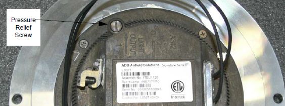
LED RWSL Take-Off Hold Light & Runway Intersection Light

        Note
        See your sales order contract for a complete warranty description.

Liability

                    WARNING
                    Use of the equipment in ways other than described in the catalog leaflet and the manual may result in personal injury,
                    death, or property and equipment damage. Use this equipment only as described in the manual.

ADB SAFEGATE cannot be held responsible for injuries or damages resulting from non-standard, unintended uses of its
equipment. The equipment is designed and intended only for the purpose described in the manual. Uses not described in the
manual are considered unintended uses and may result in serious personal injury, death or property damage.
Unintended uses, includes the following actions:

• Making changes to equipment that have not been recommended or described in this manual or using parts that are not
    genuine ADB SAFEGATE replacement parts or accessories.
• Failing to make sure that auxiliary equipment complies with approval agency requirements, local codes, and all applicable
    safety standards if not in contradiction with the general rules.
• Using materials or auxiliary equipment that are inappropriate or incompatible with your ADB SAFEGATE equipment.
• Allowing unskilled personnel to perform any task on or with the equipment.
©   ADB SAFEGATE BV
This manual or parts thereof may not be reproduced, stored in a retrieval system, or transmitted, in any form or by any means,
electronic, mechanical, photocopying, recording, nor otherwise, without ADB SAFEGATE BV's prior written consent.
This manual could contain technical inaccuracies or typographical errors. ADB SAFEGATE BV reserves the right to revise this
manual from time to time in the contents thereof without obligation of ADB SAFEGATE BV to notify any person of such
revision or change. Details and values given in this manual are average values and have been compiled with care. They are not
binding, however, and ADB SAFEGATE BV disclaims any liability for damages or detriments suffered as a result of reliance on
the information given herein or the use of products, processes or equipment to which this manual refers. No warranty is made
that the use of the information or of the products, processes or equipment to which this manual refers will not infringe any
third party's patents or rights. The information given does not release the buyer from making their own experiments and
tests.

iv
Copyright © ADB Safegate, All Rights Reserved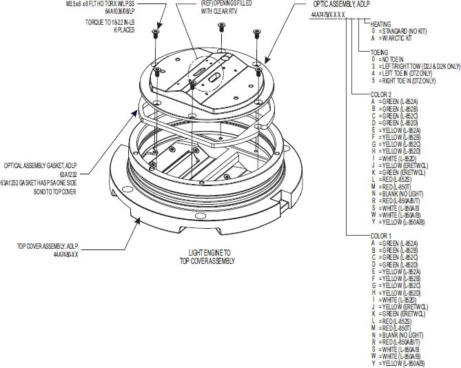
TABLE OF CONTENTS

1.0 Safety ....................................................................................................................................................................................... 1
     1.1 Safety Messages ........................................................................................................................................................................................................ 1
          1.1.1 Introduction to Safety ................................................................................................................................................................................. 2
          1.1.2 Intended Use .................................................................................................................................................................................................. 2
          1.1.3 Material Handling Precautions: Storage .............................................................................................................................................. 3
          1.1.4 Material Handling Precautions: Fasteners .......................................................................................................................................... 3
          1.1.5 Maintenance Safety ..................................................................................................................................................................................... 4
          1.1.6 Material Handling Precautions, ESD ..................................................................................................................................................... 4
          1.1.7 Arc Flash and Electric Shock Hazard ..................................................................................................................................................... 5
2.0 LED Runway Centerline and Touchdown Zone In-pavement Light .................................................................................. 7
     2.1 Introduction ................................................................................................................................................................................................................ 7
     2.2 LED RWSL Take-Off Hold Light & Runway Intersection Light ................................................................................................................. 7
3.0 Installation ............................................................................................................................................................................ 11
     3.1 Overview of Sequence of Work ........................................................................................................................................................................ 11
     3.2 Installation Overview ............................................................................................................................................................................................. 11
     3.3 INTEROPERABILITY ................................................................................................................................................................................................. 12
     3.4 Typical L-868 Assembly ........................................................................................................................................................................................ 13
     3.5 Safety Considerations ........................................................................................................................................................................................... 14
     3.6 Photobiological safety .......................................................................................................................................................................................... 14
     3.7 Verify Input Requirements and Equipment Needed ................................................................................................................................. 14
     3.8 Unpacking the Unit ................................................................................................................................................................................................ 15
     3.9 Inspect on delivery ................................................................................................................................................................................................. 15
     3.10 Store .......................................................................................................................................................................................................................... 16
     3.11 Installation on L-868 Base ................................................................................................................................................................................ 16
     3.12 Torquing and Installation Guidance for In-pavement Fixtures ........................................................................................................... 17
     3.13 Shallow base can installation .......................................................................................................................................................................... 18
          3.13.1 Installation on a Shallow Base ............................................................................................................................................................ 18
4.0 Maintenance ......................................................................................................................................................................... 21
    4.1 Safety Considerations ........................................................................................................................................................................................... 21
    4.2 Removing L-868 Base Water .............................................................................................................................................................................. 22
    4.3 Lifting Optical Unit Out of Base ........................................................................................................................................................................ 23
    4.4 Repair Procedures .................................................................................................................................................................................................. 23
         4.4.1 Opening the Optical Unit ....................................................................................................................................................................... 23
         4.4.2 Removing the LED Assembly ................................................................................................................................................................. 23
         4.4.3 Cleaning the Light Channel and Prism .............................................................................................................................................. 24
         4.4.4 Replacing Prism .......................................................................................................................................................................................... 24
         4.4.5 Replace cable lead ..................................................................................................................................................................................... 26
         4.4.6 Replace the fuse resistor (monitoring option) ................................................................................................................................ 26
         4.4.7 Closing the Optical Unit .......................................................................................................................................................................... 27
         4.4.8 Fastener Torque Table .............................................................................................................................................................................. 28
         4.4.9 Adhesives and Lubricants ....................................................................................................................................................................... 29
         4.4.10 Testing for Leaks ...................................................................................................................................................................................... 29
    4.5 Material Handling Precautions: Fasteners ..................................................................................................................................................... 31
    4.6 Bolt Torque Preventive Maintenance Schedule .......................................................................................................................................... 32
5.0 Troubleshooting ................................................................................................................................................................... 35
6.0 DTH Parts .............................................................................................................................................................................. 37
A.0 SUPPORT .............................................................................................................................................................................. 43
    A.1 ADB SAFEGATE Website ...................................................................................................................................................................................... 43
    A.2 Recycling .................................................................................................................................................................................................................... 44
         A.2.1 Local Authority Recycling ....................................................................................................................................................................... 44
         A.2.2 ADB SAFEGATE Recycling ....................................................................................................................................................................... 44

96A0475, Rev. j, 2021/04/22                                                                                                                                                                                                                v
Copyright © ADB Safegate, All Rights Reserved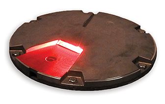
LED RWSL Take-Off Hold Light & Runway Intersection Light
TABLE OF CONTENTS

vi
Copyright © ADB Safegate, All Rights Reserved
1.0 Safety
Introduction to Safety
This section contains general safety instructions for installing and using ADB SAFEGATE equipment. Some safety instructions
may not apply to the equipment in this manual. Task- and equipment-specific warnings are included in other sections of this
manual where appropriate.

1.1 Safety Messages

HAZARD Icons used in the manual
For all HAZARD symbols in use, see the Safety section. All symbols must comply with ISO and ANSI standards.
Carefully read and observe all safety instructions in this manual, which alert you to safety hazards and conditions that may
result in personal injury, death or property and equipment damage and are accompanied by the symbol shown below.

                    WARNING
                    Failure to observe a warning may result in personal injury, death or equipment damage.

                    DANGER - Risk of electrical shock or ARC FLASH
                    Disconnect equipment from line voltage. Failure to observe this warning may result in personal injury, death, or
                    equipment damage. ARC Flash may cause blindness, severe burns or death.

                    WARNING - Wear personal protective equipment
                    Failure to observe may result in serious injury.

                    WARNING - Do not touch
                    Failure to observe this warning may result in personal injury, death, or equipment damage.

                    CAUTION
                    Failure to observe a caution may result in equipment damage.

Qualified Personnel

                    Important Information
                    The term qualified personnel is defined here as individuals who thoroughly understand the equipment and its safe
                    operation, maintenance and repair. Qualified personnel are physically capable of performing the required tasks, familiar
                    with all relevant safety rules and regulations and have been trained to safely install, operate, maintain and repair the
                    equipment. It is the responsibility of the company operating this equipment to ensure that its personnel meet these
                    requirements.
                    Always use required personal protective equipment (PPE) and follow safe electrical work practice.

96A0475, Rev. j, 2021/04/22                                                                                                                    1
Copyright © ADB Safegate, All Rights Reserved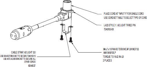
LED RWSL Take-Off Hold Light & Runway Intersection Light
Safety

1.1.1 Introduction to Safety

                   CAUTION
                   Unsafe Equipment Use
                   This equipment may contain electrostatic devices, hazardous voltages and sharp edges on components
                   •    Read installation instructions in their entirety before starting installation.
                   •    Become familiar with the general safety instructions in this section of the manual before installing,
                        operating, maintaining or repairing this equipment.
                   •    Read and carefully follow the instructions throughout this manual for performing specific tasks and
                        working with specific equipment.
                   •    Make this manual available to personnel installing, operating, maintaining or repairing this
                        equipment.
                   •    Follow all applicable safety procedures required by your company, industry standards and
                        government or other regulatory agencies.
                   •    Install all electrical connections to local code.
                   •    Use only electrical wire of sufficient gauge and insulation to handle the rated current demand. All
                        wiring must meet local codes.
                   •    Route electrical wiring along a protected path. Make sure they will not be damaged by moving
                        equipment.
                   •    Protect components from damage, wear, and harsh environment conditions.
                   •    Allow ample room for maintenance, panel accessibility, and cover removal.
                   •    Protect equipment with safety devices as specified by applicable safety regulations
                   •    If safety devices must be removed for installation, install them immediately after the work is
                        completed and check them for proper functioning prior to returning power to the circuit.

                   Failure to follow this instruction can result in serious injury or equipment damage

Additional Reference Materials

                    Important Information

                    •   IEC - International Standards and Conformity Assessment for all electrical, electronic and related technologies.

                    •   IEC 60364 - Electrical Installations in Buildings.

                    •   FAA Advisory: AC 150/5340-26 (current edition), Maintenance of Airport Visual Aid Facilities.

                    •   Maintenance personnel must refer to the maintenance procedure described in the ICAO Airport Services Manual,
                        Part 9.

                    •   ANSI/NFPA 79, Electrical Standards for Metalworking Machine Tools.

                    •   National and local electrical codes and standards.

1.1.2 Intended Use

                   CAUTION
                   Use this equipment as intended by the manufacturer
                   This equipment is designed to perform a specific function, do not use this equipment for other purposes

                   •    Using this equipment in ways other than described in this manual may result in personal injury, death
                        or property and equipment damage. Use this equipment only as described in this manual.

                   Failure to follow this instruction can result in serious injury or equipment damage

2
Copyright © ADB Safegate, All Rights Reserved
1.1.3 Material Handling Precautions: Storage
CAUTION
Improper Storage
Store this equipment properly
• If equipment is to be stored prior to installation, it must be protected from the weather and kept free
of condensation and dust.
Failure to follow this instruction can result in equipment damage
1.1.4 Material Handling Precautions: Fasteners
DANGER
Foreign Object Damage - FOD
This equipment may contain fasteners that may come loose - torque properly.
• Only use fasteners of the same type as the one originally supplied with the equipment.
• Use of incorrect combination of gaskets, bolts and nuts can create severe damages to the product
installation and create safety risk .
• You need to know what base the light fixture will be installed in, in order to chose the correct gasket,
bolts and nuts.
• Bolt type, length, and torque value are determined by type of base, height of spacers used, and clamp
force required in FAA Engineering Brief No 83 (latest revision).
• Due to the risk of bolts vibrating loose, do not use any type of washer with the fixing bolts (such as
split lock washers) other than an anti-vibration washer. Anti-vibration washers as defined in FAA EB
83 (latest edition) must be used. For installations other than FAA, use the base can manufacturer's
recommendations.
• Always tighten the fasteners to the recommended torque. Use a calibrated torque wrench and apply
the recommended adhesive type.
• Obey the instructions of the adhesives necessary for the fasteners.
Failure to follow these warnings may cause the fasteners to loosen, damage the equipment,
potentially to loosen the equipment. This can lead to a highly dangerous situation of FOD, with
potential lethal consequences.
Note
To minimize the risk of errors, the ADB SAFEGATE Sales Representative will have information on which gasket goes
with which base. This information is also provided in the product Data sheets, the User Manuals and the Spare Part
Lists.
CAUTION
Use of incorrect combination of gaskets, bolts and nuts can create severe damages to the product installation and
create multiple safety risks.
To obtain a safe and watertight installation the O-ring and retaining bolt stated in the document must be used.
You need to know what base the light fixture will be installed in, in order to choose the correct gasket, bolts and nuts.
Failure to follow these cautions can result in equipment damage or aircraft FOD.
96A0475, Rev. j, 2021/04/22 3
Copyright © ADB Safegate, All Rights ReservedLED RWSL Take-Off Hold Light & Runway Intersection Light
Safety
1.1.5 Maintenance Safety
DANGER
Electric Shock Hazard
This equipment may contain electrostatic devices
• Do not operate a system that contains malfunctioning components. If a component malfunctions,
turn the system OFF immediately.
• Disconnect and lock out electrical power.
• Allow only qualified personnel to make repairs. Repair or replace the malfunctioning component
according to instructions provided in its manual.
Failure to follow these instructions can result in death or equipment damage
1.1.6 Material Handling Precautions, ESD
CAUTION
Electrostatic Sensitive Devices
This equipment may contain electrostatic devices
• Protect from electrostatic discharge.
• Electronic modules and components should be touched only when this is unavoidable e.g. soldering,
replacement.
• Before touching any component of the cabinet you shall bring your body to the same potential as the
cabinet by touching a conductive earthed part of the cabinet.
• Electronic modules or components must not be brought in contact with highly insulating materials
such as plastic sheets, synthetic fiber clothing. They must be laid down on conductive surfaces.
• The tip of the soldering iron must be grounded.
• Electronic modules and components must be stored and transported in conductive packing.
Failure to follow this instruction can result in equipment damage
4
Copyright © ADB Safegate, All Rights Reserved1.1.7 Arc Flash and Electric Shock Hazard
DANGER
Series Circuits have Hazardous Voltages
This equipment produces high voltages to maintain the specified current - Do NOT Disconnect while
energized.
• Allow only qualified personnel to perform maintenance, troubleshooting, and repair tasks.
• Only persons who are properly trained and familiar with ADB SAFEGATE equipment are permitted to
service this equipment.
• An open airfield current circuit is capable of generating >5000 Vac and may appear OFF to a meter.
• Never unplug a device from a constant current circuit while it is operating; Arc flash may result.
• Disconnect and lock out electrical power.
• Always use safety devices when working on this equipment.
• Follow the recommended maintenance procedures in the product manuals.
• Do not service or adjust any equipment unless another person trained in first aid and CPR is present.
• Connect all disconnected equipment ground cables and wires after servicing equipment. Ground all
conductive equipment.
• Use only approved ADB SAFEGATE replacement parts. Using unapproved parts or making
unapproved modifications to equipment may void agency approvals and create safety hazards.
• Check the interlock systems periodically to ensure their effectiveness.
• Do not attempt to service electrical equipment if standing water is present. Use caution when
servicing electrical equipment in a high-humidity environment.
• Use tools with insulated handles when working with airfield electrical equipment.
Failure to follow these instructions can result in death or equipment damage
96A0475, Rev. j, 2021/04/22 5
Copyright © ADB Safegate, All Rights ReservedLED RWSL Take-Off Hold Light & Runway Intersection Light Safety 6 Copyright © ADB Safegate, All Rights Reserved
2.0 LED Runway Centerline and Touchdown Zone In-pavement
Light
This user manual covers the LED In-pavement Runway Centerline and DTH-LP Light installation and maintenance.

2.1 Introduction

DTH RWSL

2.2 LED RWSL Take-Off Hold Light & Runway Intersection Light

Compliance with Standards

FAA:                L-850T(L) AC 150/5345-46 (Current Edition) and the FAA Engineering Brief No. 67. ETL Certified. Complies with FAA
                    Runway Status Light System Take-off Hold Light (THL) and Runway Intersection Light (RIL) requirements in FAA AC
                    150/5340-30 Appendix 7 and FAA Engineering Brief 64.

Uses

FAA L-850T(L) RWSL THL-RIL          Used in FAA Runway Status Light THL applications. Fixture is unidirectional traffic signal red.

Features

• The evolution of the most successful LED lights in the world, fully adapted to the characteristics of LED lighting sources
• Very low energy consumption
• Greatly reduced maintenance: calculated MTBF of 56,000 hours at 6.6 A
• Style 3-Low protrusion above ground of ≤0.25 inch (6.3 mm) reduces vibrations caused by aircraft landing gear in both
   the light fixture and the landing gear, increasing fixture life.
• Increased traffic efficiency and availability of the runways due to the reduction in maintenance
• Very low working temperature, ensuring longer component life
• Full compatibility with conventional airfield lighting series circuits. No need to replace the CCRs, series transformers or
   cables on existing circuits.
• Substantial investment reduction for new installations using smaller CCR size and series transformers, resulting from a
   lower installed load
• Fully dimmable lights, respecting the response curve of traditional halogen lights. Operates on the full range of 2.8 A to
   6.6 A.

96A0475, Rev. j, 2021/04/22                                                                                                             7
Copyright © ADB Safegate, All Rights Reserved
LED RWSL Take-Off Hold Light & Runway Intersection Light
LED Runway Centerline and Touchdown Zone In-pavement Light
• Rugged lightning protection complies with ANSI/IEEE C62.41-1991 Location Category C2 given in FAA Eng. Brief 67.
Category C2 is defined as a 1.2/50μS - 8/20 μS combination wave, with a peak voltage of 10,000 V and a peak current of
5,000 A.
• When turned on, light rise time is low. The light is perfectly adapted for any incursion protection system.
• Environment-friendly, precision-cast aluminum alloy top, intermediate and bottom covers
• Corrosion-resistant stainless steel hardware. Use of Torx screws ensures ease of maintenance.
DTH-LP lights are part of a complete range of LED in-pavement lights, featuring innovative characteristics, as a leverage for:
Reliability
• Additional watertightness barriers, protecting both the electronics and the LEDs in case of accidental water ingress, along
the prism or the gaskets as well as along the cables
• Prisms of small dimensions installed in a deep optical channel with no negative window slope: optimal protection against
rubber deposit, scratches and shocks
Maintenance Friendliness
• Maintenance-friendly: components subject to wear or damage like prisms and cables can easily be replaced. Neither
sealing compounds nor resin are required
• Innovative design of the cable entry, permitting replacement without the need to open the light. This eliminates the risk of
water leakage due to a pinched cable.
• Reduced number of components for maintenance simplicity
• Pressure-release plug for water-tightness testing of fixture after overhaul
Low protrusion without negative slope
• Limited height above pavement of 6.3 mm (0.25 in) reduces the risk of damage during winter operations or by towbarless
tugs
• Despite the low protrusion, no part of the prism is below ground level, avoiding loss of photometry during rainfall and
sedimentation on the bottom of the prism
Operating Conditions
Temperature: -40 °C to +55 °C (-40 °F to +131 °F)
Altitude: Sea level to 10,000 feet (3000 m)
Relative Humidity: Up to 100%
Dimensions
Top cover outside diameter: 11.94 in (30.33 cm)
Top cover bolt-circle diameter (L-868B): 11.25 in (28.58 cm)
Bottom cover outside diameter(max.): 9.94 in (25.25 cm)
1
Depth: 4 in (10.16 cm)
Notes
1 From the bottom of the top cover to the bottom of the fixture.
8
Copyright © ADB Safegate, All Rights ReservedPower Supply
It is recommended that the DTH-LP fixture be powered from a dedicated CCR and that separate remote controls are available.
DTH-LP lights have been designed to work with any FAA-compliant transformer up to 150 W without affecting the
performance or lifetime of the light fixture or transformer. See data sheet 3033 for more details on recommended isolation
transformers specified below.
L-850T(L)/DTH-LP Fixture Load* Isolation Transformer Isol. XF Load CCR Load
Without Heater 35 VA 30/45 W 6 VA 41 VA
Note
Load includes ADB Safegate BRITE III Remote device.
Packaging
In cardboard box: 7 × 13 × 13 in (17.8 × 33 × 33 cm)
Weight with packing: 22 lb (9.98 kg)
Weight without packing: 17.75 lb (8.05 kg)
96A0475, Rev. j, 2021/04/22 9
Copyright © ADB Safegate, All Rights ReservedLED RWSL Take-Off Hold Light & Runway Intersection Light LED Runway Centerline and Touchdown Zone In-pavement Light 10 Copyright © ADB Safegate, All Rights Reserved
3.0 Installation

        WARNING
        Read the instructions in their entirety before starting installation.

This section provides installation instructions for the DTH-LP, LED light fixtures.
This section provides instructions for installing the in-pavement lights. Refer to airport project plans and specifications for
specific installation instructions. The installation must conform to the applicable sections of the National Electric Code and
local codes.

3.1 Overview of Sequence of Work

• Electrical contractor locates new light bases and interconnecting conduit trench, and excavates for light base bottom
   section by saw cutting or core drilling. Electrical contractor prepares subgrade and stone subbase, sets bottom section
   with rebar, rigid steel conduit stubs, drain, and pours high early strength concrete-encasement excavation. Electrical
   contractor shall record can locations and elevations of mud plate after concrete-encasement.
• Electrical contractor excavates conduit trench, installs rigid steel and fittings, backfills conduit trench with high early
   strength concrete.
• General contractor prepares and installs concrete pavement. Electrical contractor makes a pilot core to find mud plate
   center point indent before final core-drilling.
• Electrical contractor core-drills concrete pavement. Electrical contractor installs top section, y-flange ring, space and
   lighting fixture, and pours epoxy joint sealer. Provide space for adjustment with spacers, maximum number of spacers
   shall be 3.
• See specific details as shown in FAA AC 150/5340-30 (current edition).

3.2 Installation Overview

On a shallow base.
The 8” dia. base is secured in the pavement by means of resin. Correct positioning and leveling are obtained with a jig with
sighting telescope. Wires between the light and the series transformer are installed either in saw cuts in the pavement filled
with resin or in pipes in the lower concrete layers. Mounting on existing or new, larger diameter bases, is made possible by
means of dedicated adapter rings.
Figure 1: Installation on 8” shallow base

On a FAA L-868B size B steel base.
The 8” dia. light is mounted in an 8” to 12” dia. snow plow or adapter ring bolted onto the base. The 12” fixture is directly
mounted without a separate ring. The bases are interconnected by means of conduits protecting the cables. See FAA AC
150/5340-30 for additional design guidance on deep base cans. The series transformer is installed under the light or in a
separate pit. See data sheet A.05.120 or DS2012 for more information on base cans.

96A0475, Rev. j, 2021/04/22                                                                                                       11
Copyright © ADB Safegate, All Rights Reserved
LED RWSL Take-Off Hold Light & Runway Intersection Light
Installation
3.3 INTEROPERABILITY
Top cover versions
Note
Please check interoperability matrix for information on torque values and compatibility towards different bases.
12
Copyright © ADB Safegate, All Rights Reserved3.4 Typical L-868 Assembly
Figure 2: Diagram of the Fixture Installed in a 1-Piece Base Can
3/8-16 Hex Cap Screw SEMI-FLUSH
(per FAA EB-83 (latest revision) LIGHT FIXTURE
TYPE L-85X (TYP.)
3/8” Anti-vibration Washer L868B FLANGE RING 12.25" O.D.
(per FAA EB-83 (latest revision) 3/4" THICK, 5402/12Y
WITH O-RING GASKET (TYP.)
FIXTURE TOP EDGE TO BE
1 1/4" WIDE X 1-1/2" DEEP GROOVE (TYP.)
+0/- 16 " BELOW GRADE
In order to maintain +0/- 1/16” below grade, per FAA installation tolerance,
0.75" a maximum of 3 spacers may be used.
L868B SPACER RING(S)
GROUND WIRE
6A WG
1-1/2" (TYP.)
L868B LIGHT BASE
L-823 SECONDARY CONNECTOR
L-823 PRIMARY CONNECTOR
(TYP.) (HEATSHRINK OPTIONAL)
GROMMET
2" PVC CONDUIT W/BELL END
ISOLATION TRANSFORMER
SIZE AS REQUIRED
TRANSFORMER SUPPORT
(TYP.)
3/4" DRAIN HOLE (CENTERED)
1. Torque according to: FAA EB-83 (latest revision).
Figure 3: Anti-vibration washer example
Cams (or steps) of the lock-washer
must face each other
96A0475, Rev. j, 2021/04/22 13
Copyright © ADB Safegate, All Rights ReservedLED RWSL Take-Off Hold Light & Runway Intersection Light
Installation
CAUTION
Per FAA AC 150/5340-30, Chapter 10, and FAA Engineering Brief No 83 (latest revision), it is extremely important that
other types of washers, such as split washers, must not be used. Failure to use properly installed anti-vibration lock
washers will cause mounting bolts to become loose. The cams (or steps) of each half of the lock washer must face
each other.
3.5 Safety Considerations
Read the installation section of all system component manuals before starting these steps. A thorough understanding of
system components and their requirements will promote safe and efficient installation. See FAA AC 150/5340-30, Design and
Installation Details for Airport Visual Aids, and site plans and specifications for field installation of runway and taxiway in-
pavement lights.
DANGER
Failure to follow these safety procedures can result in personal injury or death.
• Allow only qualified personnel to install ADB SAFEGATE and auxiliary equipment. Use only approved equipment.
Using unapproved equipment in an approved system may void FAA approvals. Observe and follow the safety
instructions in this document and all other related documentation.
• Make sure all equipment is rated and approved for the environment where it is being used.
• Follow all instructions for installing components and accessories.
• Install all electrical connections in compliance with local and national codes and regulations.
• Use only electrical wire of sufficient gauge and insulation to handle the rated current demand. All wiring must
meet local and national codes.
• Route electrical wiring along a protected path. Make sure it will not be damaged by moving equipment.
• Protect components from damage, wear and harsh environmental conditions.
• Allow ample clearance for maintenance, panel accessibility and cover removal.
• Protect equipment with safety devices as specified by applicable safety regulations.
• If safety devices must be removed for installation, reinstall them immediately after the work is completed and
check them for proper functioning.
• The cord set must be protected prior to installation.
3.6 Photobiological safety
CAUTION
Photobiological safety conforming with IEC 62471
RISK GROUP 0 or 1: Optical radiation emitted from LED lights may be harmful to the eyes. Do not stare with at the
light source with bare eyes at a fixture operating at high intensity. Use protection goggles or similar protection
method.
Goggles with a transmission factor not higher than 5% in the 400-530 nm band have been tested and provide
adequate protection.
3.7 Verify Input Requirements and Equipment Needed
The In-pavement light fixture is designed for connection to a 6.6A or 20A series lighting circuit via an L‑830 (60 Hz) or L-831
(50 Hz) isolation transformer.
14
Copyright © ADB Safegate, All Rights ReservedMake sure you have the necessary tools and materials ready for installation (not supplied). Also consider other tools that
might be needed based on site-specific conditions.
Table 1: Suggested Tools and Materials for Installation and Repair
Qty. Description Qty. Description
1 Torque wrench 1 Set of screwdrivers, one with 3/8" (9.525mm) minimum
blade width
1 Alignment jig
1 Diamond-faced core drill As needed Silicone grease
1 Diamond-faced saw, 3/8" (9.525mm) As needed Joint sealing filler
thick
1 Crimping tool 1 Pressure test fitting assembly
1 Small water suction pump As needed Dow Corning Molykote® 3452 or equal (P/N 67A0095) -
used on top cover prism seal
2 Eyebolts, 3/8 inch (9.525mm) diameter
1 Lifting rod, 16 inches (406mm) long As needed Novagard® Silicone Versilube® G322L™ (P/N 67A0009) -
used on O-ring between top cover and inner pan
1 or 2 L-830 / L-831 isolation transformer assembly; also may be applied to four nipples of inner pan
1 Set of fiber brushes assembly to install optical assembly
1 Set of socket wrenches, 1/2" (12.7mm)
drive
3.8 Unpacking the Unit
To reduce the possibility of damaging the light assembly, unpack the RELIANCE light fixtures at the installation site. If damage
to any equipment is noted, file a claim form with the carrier immediately.
When receiving the light fixture, open the box and verify that the characteristics of the light fixture correspond to the design
requirements, such as type, color etc. When installing an IQ0 light fixture where the function is to be activated at a later stage,
make sure to register product information, such as PID/SN and position of the light fixture in, for example, a site
documentation table. The information is required for remote activation and administration of IQ functionality from a
substation.
3.9 Inspect on delivery
1. Inspect all packings for visible damage.
2. Open every damaged box and inspect the contents for damage.
3. Immediately fill a claim form with the carrier if any fixture is damaged.
4. Store the fixture in its original packing in a protected area.
Note
If damage to any equipment is noted, file a claim form with the carrier immediately.
WARNING
Do not damage the cable insulation.
CAUTION
Do not unpack the fixture before it is at the installation site to avoid damage due to transportation and handling.
96A0475, Rev. j, 2021/04/22 15
Copyright © ADB Safegate, All Rights ReservedLED RWSL Take-Off Hold Light & Runway Intersection Light Installation 3.10 Store Store the fixture in its original packing in a protected area. Indoor storage: • Storage temperature: 14°F to 122°F (-10°C to +50°C). • Humidity:
7. If present, lubricate the labyrinth gasket with water. soap may be added to the water (8" only).

            CAUTION
            Do not use silcon or any other type of grease. Avoid the use of soap that contains silicon or glycerin.

 8. Attach the six fixing bolts and anti-vibration washers. [See FAA EB-83 (latest revision)]

            CAUTION
            Due to the risk of bolts vibrating loose, do not use any type of washer with the fixing bolts (such as split lock
            washers) other than an anti-vibration washer. Anti-vibration washers as defined in FAA EB-83 (latest revision).

 9. Turn on the power to determine whether the fixture will illuminate. Operate for a minimum of five minutes.

3.12 Torquing and Installation Guidance for In-pavement Fixtures

In-pavement fixtures must be installed according to the plans and specifications; the applicable regulatory guidance; and the
following guidance. The importance of using the proper fixture clamping components and bolt torque to minimize the risk for
fixture failure or loosening of clamping components cannot be overemphasized. Refer to FAA Engineering Brief No 83 (latest
revision) for torque and installation guidelines for this fixture.
Also see our Product Center at www.adbsafegate.com.

        CAUTION
        Read installation instructions in their entirety before starting installation.

        • Failure to follow the installation guidance could result in bolt loosening or bolts breaking off, resulting in
            catastrophic failure of the fixture and/or the mounting system components.
        • Failure to follow these warnings may result in serious injury or equipment damage.

96A0475, Rev. j, 2021/04/22                                                                                                     17
Copyright © ADB Safegate, All Rights Reserved
LED RWSL Take-Off Hold Light & Runway Intersection Light
Installation
3.13 Shallow base can installation
Shallow base cans may be non-load bearing or load bearing depending on location or fixture application. Following are
specific requirements to insure that an either an elevated or an in-pavement fixture is properly installed.
CAUTION
Read installation instructions in their entirety before starting installation.
Fasteners:
• Make sure the power is OFF when you install or remove any fixture.
• Only use fasteners of the same type as the one originally supplied with the mounting support. See Base O-ring
and Bolt Selection.
• Always tighten the fasteners to the recommended torque. Use a calibrated torque wrench and apply the
recommended adhesive type.
• If this is not the case, this may cause the fasteners to loosen, damage the fixture, potentially to loosen the fixture.
This can lead to a highly dangerous situation of FOD, with potential lethal consequences.
• Obey the instructions of the adhesives necessary for the fasteners.
• Only install the fixture on mounting supports:
• That ADB Safegate has approved;
• That are installed according to the Instruction Manual of the mounting support.
• Failure to do so can result in a highly dangerous situation of FOD, with potential lethal consequences.
Failure to follow these warnings may result in serious injury or equipment damage.
CAUTION
Proper Operation:
• The fixture is supplied from a 6.6 A series circuit;
• The series circuit is powered by a Constant Current Regulator that complies with IEC 61822;
• The transformer is an AGL series transformer that complies with IEC 61823.
• The power of the series transformer shall not exceed 200 W, for versions with the monitoring option.
• The mounting support is correctly earthed. Failure to do so will void the warranty for all damages that occur as a
result of voltage surges.
• Never hold the fixture by the cable leads. This can damage the insulation, break the waterproof seal and cause
insulation faults and water leakage.
Note
See the Instruction Manual of the mounting support for instructions on how to earth the mounting support.
3.13.1 Installation on a Shallow Base
Installing the light fixture on a shallow base involves preparing the pavement recess and wireways, then installing the light
fixture on a shallow base.
See FAA AC 150/5345-30 and the project site-specific plans and specifications for details on shallow base installation.
18
Copyright © ADB Safegate, All Rights ReservedAlso follow the applicable instructions in the previous section, when connecting, installing and powering the fixture.
Figure 4: Example of a Shallow Base Installation
3/8-16 Hex Cap Screw SEMI-FLUSH
(per FAA EB-83 (latest revision) LIGHT FIXTURE
TYPE L-85X (TYP.) L868B FLANGE PLATE 12.25" O.D.
3/8” Anti-vibration Washer
(per FAA EB-83 (latest revision)
L868B FLANGE RING 12.25" O.D.
3/4" THICK, 5402/12Y L868B SPACER RING(S)
WITH O-RING GASKET (TYP.)
FIXTURE TOP
EDGE TO BE 0.75"
+0 - (-1/16)" L868B SPACER RING(S)
BELOW GRADE L-823 PRIMARY CONNECTOR
1-1/2" (TYP.)
L868B LIGHT BASE
GROUND WIRE L868B LIGHT BASE
6 AWG OR LARGER GROMMET
2" PVC CONDUIT W/BELL END
L-823 PRIMARY
Earth Ground GROMMET EXTENSION
L868B JUNCTION HOUSING
3/4" DRAIN HOLE (CENTERED)
Earth Ground L-823 SECONDARY CONNECTOR
Earth Ground
ISOLATION TRANSFORMER
(max 3 per can)
3/4" DRAIN HOLE (CENTERED)
(if used)
1. Torque according to: FAA EB-83 (latest revision).
Figure 5: Anti-vibration washer example
Cams (or steps) of the lock-washer
must face each other
CAUTION
Per FAA AC 150/5340-30, Chapter 10, and FAA Engineering Brief No 83 (latest revision), it is extremely important that
other types of washers, such as split washers, must not be used. Failure to use properly installed anti-vibration lock
washers will cause mounting bolts to become loose. The cams (or steps) of each half of the lock washer must face
each other.
96A0475, Rev. j, 2021/04/22 19
Copyright © ADB Safegate, All Rights ReservedLED RWSL Take-Off Hold Light & Runway Intersection Light Installation 20 Copyright © ADB Safegate, All Rights Reserved
4.0 Maintenance

        WARNING
        Read the instructions in their entirety before starting maintenance.

This section provides maintenance instructions for the DTH-LP light fixtures.

4.1 Safety Considerations

Read the installation section of all system component manuals before installing this equipment. A thorough understanding of
system components and their requirements will promote safe and efficient installation. See FAA AC 150/5340-30, Design and
Installation Details for Airport Visual Aids, and site plans and specifications for field installation of runway and taxiway in-
pavement lights.

96A0475, Rev. j, 2021/04/22                                                                                                   21
Copyright © ADB Safegate, All Rights Reserved
LED RWSL Take-Off Hold Light & Runway Intersection Light
Maintenance
WARNING
Failure to follow these safety procedures can result in personal injury or death.
• Allow only qualified personnel to install ADB Airfield Solutions and auxiliary equipment. Use only approved
equipment. Using unapproved equipment in an approved system may void FAA approvals. Observe and follow the
safety instructions in this document and all other related documentation.
• Make sure all equipment is rated and approved for the environment where it is being used.
• Follow all instructions for installing components and accessories.
• Install all electrical connections in compliance with local and national codes and regulations.
• Use only electrical wire of sufficient gauge and insulation to handle the rated current demand. All wiring must
meet local and national codes.
• Route electrical wiring along a protected path. Make sure it will not be damaged by moving equipment.
• Protect components from damage, wear and harsh environmental conditions.
• Allow ample clearance for maintenance, panel accessibility and cover removal.
• Protect equipment with safety devices as specified by applicable safety regulations.
• If safety devices must be removed for installation, reinstall them immediately after the work is completed and
check them for proper functioning.
• The cord set must be protected prior to installation.
Table 2: Maintenance Schedule
Clean channel and prism. Refer to Cleaning
Light Channel and Prism in this section.
If the prism is not dirty,
Check for dirty channel and lens.
Weekly
For low light output • Replace the fixture.
• Replace the faulty component in the
workshop.
• If there is moisture present, replace the
fixture.
Monthly
Visually check for moisture in the light fixture.
(or more frequently during rainy seasons) • Replace faulty parts.
• Clean, dry, and inspect the light assembly.
Every 60 days, Check for improper torque on hold down Refer to “Torquing and Installation Guidance
or whenever the light assembly is serviced bolts. for In-pavement Fixtures” on page 11.
If consistent with local airport practice, pump
Check for six inches (150 mm) of water in the
Semiannually water from base. Remove and inspect light
L-868 base.
for water damage.
After snow removal Check for damaged light fixtures. Replace damaged fixtures.
4.2 Removing L-868 Base Water
WARNING
Turn off the circuit when checking the water level.
If consistent with airport practice, check the water level in the L-868 base on a regular schedule. If more than six inches (150
mm) of water in the light base is found, pump the water from the base and remove and inspect the entire light assembly for
water damage. Cover the L-868 base with the appropriate steel cover plate after removing the light assembly.
22
Copyright © ADB Safegate, All Rights ReservedNote
Water entering the L-868 base can become a serious problem, since freezing water can rupture the base.
4.3 Lifting Optical Unit Out of Base
To lift the optical unit from the light base, perform the following procedure:
1. Remove the six fixing screws and washers or self locking nuts.
2. Fit the appropriate lifting tool into both threaded holes located (180 degrees apart) in the cover, lift the optical unit out of
the base and place the optical unit next to the base.
3. Disconnect the light fixture wires from the power wires coming from the transformer(s).
4. Mount a serviced or new light fixture as described in Installation on L-868 Base in the Installation section.
5. Take the in-pavement fixture unit back to the maintenance base where it can be serviced entirely.
CAUTION
Never hold the light fixture by the wires. This may damage the insulation, break the waterproof seal, and cause
insulation faults and water leakage.
4.4 Repair Procedures
4.4.1 Opening the Optical Unit
To open the optical unit, perform the following procedure:
1. Remove the pressure release screw (A).
2. Dispose of the gasket of the pressure release screw.
3. Remove the inner cover screws (B).
4. Dispose of the inner cover screws.
5. Remove the upper cover assy (C).
Note
Put a screwdriver in the notches.
6. Remove the gasket (E).
7. Dispose of the gasket.
Figure 6: Disassemble the Light Unit
4.4.2 Removing the LED Assembly
1. Turn the top cover assembly over.
2. Remove the LED Assembly pressure release screw.
3. Remove the four screws attaching the LED assembly to the top cover assembly.
96A0475, Rev. j, 2021/04/22 23
Copyright © ADB Safegate, All Rights ReservedLED RWSL Take-Off Hold Light & Runway Intersection Light
Maintenance
Note
The optical assembly is connected to the PCB. If you pull too hard, you can damage the PCB. Disconnect the wires
carefully.
4. Remove and dispose of the gasket.
4.4.3 Cleaning the Light Channel and Prism
To clean the light channel and prism, perform the following procedure:
1. Remove the four screws of the prism retaining bracket.
Gently remove the prism and the prism seal.
2. Use a suitable fiber brush to remove all accumulated debris from the light channel.
3. Clean the outer surface of the prism using liquid glass cleaner.
If the prism is coated with a substance impervious to the cleaner, apply a suitable solvent sparingly with a wad of cotton
or a patch of cloth. After the solvent has acted, remove the softened coating with a clean piece of cotton or cloth. Dry the
prism gently with dry, oil-free compressed air at a pressure no greater than 10 psi (69 kPa) to evaporate or remove all
remaining cleaner.
4. If the prism is damaged go to the next procedure.
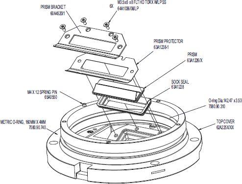
4.4.4 Replacing Prism
Replace the prism if it is broken or its surface is badly pitted or scarred.
To replace the prism, perform the following procedure:
CAUTION
Always dispose of the gaskets and the screws when you disassemble the prism.
Prism Removal
1. Remove the upper cover assembly.
See Opening the Optical Unit.
2. Remove the LED Assembly Following the steps above.
3. Remove the prism screws (A).
24
Copyright © ADB Safegate, All Rights Reserved4. Dispose of the prism screws. 5. Remove the prism bracket (B). 6. Remove the prism (D). 7. Remove the prism gasket (C). 8. Dispose of the prism gasket. Replace the Prism Prepare 9. Make sure that all parts are clean. 10. Pay special attention to the parts where the gasket must fit. Assemble prism 11. Install a new prism gasket (C). 12. Install a new prism (D). Tilt the prism a little and press the prism firmly. 13. Make sure the prism and the prism gasket are correctly in position. If it is not the case re-install the new prism and prism gasket. 14. Make sure you installed the correct prism and prism gasket. 15. Clean the surface of the new prism with a methanol moist cloth. 16. Install the prism bracket (B). 17. Install but do not tighten the new prism screws (A). 18. Tighten the prism screws crosswise. See Fastener Torque Table. 19. Install the upper cover assembly. See Fastener Torque Table. 96A0475, Rev. j, 2021/04/22 25 Copyright © ADB Safegate, All Rights Reserved
You can also read