OUTDOOR LED MOTORSPORTS DISPLAYS - INSTALLATION MANUAL P1198
←
→
Page content transcription
If your browser does not render page correctly, please read the page content below
OUTDOOR LED
                             MOTORSPORTS DISPLAYS
                             INSTALLATION MANUAL
                                           P1198
                                           DD2956770
                                             Rev 06
                                         03 August 2021

                                    Motorsports Models
                               AR-1522     AR-2426   CH-3105
                               AR-2401     AR-2427   DR-2482
                               AR-2402     AR-2428   DR-2483
                               AR-2404     AR-2429   DR-3682
                               AR-2407     CH-3001   DR-3683
                               AR-2421     CH-3002   DR-4882
                               AR-2422     CH-3003   DR-4883
                               AR-2423     CH-3004
                               AR-2424     CH-3006

201 Daktronics Drive
Brookings, SD 57006-5128
www.daktronics.com/support
800.325.8766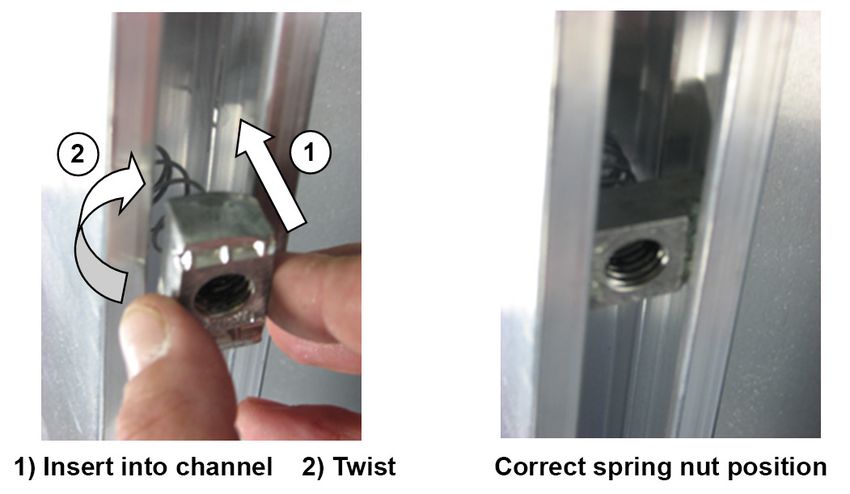
FCC Statement                                                Industry Canada Regulatory Information
Supplier Declaration of Conformity (SDoC)                    This Class A digital apparatus complies with Canadian
This product complies with Part 15 of the FCC Rules.         ICES-003.
Operation is subject to the following two conditions: (1)    Cet appareil numérique de la classe A est conforme à
This device may not cause harmful interference, and          la norme NMB-003 du Canada.
(2) this device must accept any interference received,
including interference that may cause undesired
operation.                                                   Inquiries
                                                             Contact Daktronics with any questions regarding our
Note: This equipment has been tested and found to            product compliance.
comply with the limits for a Class A digital device,
pursuant to part 15 of the FCC Rules. These limits are       Mail:
designed to provide reasonable protection against            Daktronics
harmful interference when the equipment is operated          201 Daktronics Dr.
in a commercial environment. This equipment                  Brookings, SD 57006 USA
generates, uses, and can radiate radio frequency
energy and, if not installed and used in accordance          Phone:
with the instruction manual, may cause harmful               800-325-8766
interference to radio communications. Operation of
this equipment in a residential area is likely to cause      Website:
harmful interference in which case the user will be          www.daktronics.com
required to correct the interference at their own
expense.

Warning: The user is cautioned that changes and
modifications made to the equipment without the
approval of manufacturer could void the user’s
authority to operate this equipment.

Copyright © 2015-2021
All rights reserved. While every precaution has been taken in the preparation of this manual, the publisher assumes no
responsibility for errors or omissions. No part of this book covered by the copyrights hereon may be reproduced or copied
in any form or by any means—graphic, electronic, or mechanical, including photocopying, taping, or information
storage and retrieval systems—without written permission of the publisher.
Daktronics trademarks are property of Daktronics, Inc. All other trademarks are property of their respective companies.
Table of Contents
1 Introduction���������������������������������������������������������������������������������������������������������������������������1
Important Safeguards��������������������������������������������������������������������������������������������������������������������������1
Specifications Label�����������������������������������������������������������������������������������������������������������������������������1
Resources����������������������������������������������������������������������������������������������������������������������������������������������1
Troubleshooting������������������������������������������������������������������������������������������������������������������������������������2
Display Controllers��������������������������������������������������������������������������������������������������������������������������������2
Product Safety Approval���������������������������������������������������������������������������������������������������������������������2
2 Mechanical Installation�������������������������������������������������������������������������������������������������������3
Lifting������������������������������������������������������������������������������������������������������������������������������������������������������3
Vertical Display Mounting�������������������������������������������������������������������������������������������������������������������4
Mounting Horizontal Displays��������������������������������������������������������������������������������������������������������������6
Clamping Angles������������������������������������������������������������������������������������������������������������������������������6
I-Beam Clamps (Drag Racing)�������������������������������������������������������������������������������������������������������7
Go-Kart Display Mounting�������������������������������������������������������������������������������������������������������������������8
CH-3105���������������������������������������������������������������������������������������������������������������������������������������������9
Ad Panel Mounting������������������������������������������������������������������������������������������������������������������������������9
Unistrut Attachment��������������������������������������������������������������������������������������������������������������������������9
Clamping Angles����������������������������������������������������������������������������������������������������������������������������10
I-Beam Clamps (Drag Racing)�����������������������������������������������������������������������������������������������������11
3 Electrical Installation����������������������������������������������������������������������������������������������������������12
Installation Overview��������������������������������������������������������������������������������������������������������������������������12
Power���������������������������������������������������������������������������������������������������������������������������������������������������15
Grounding���������������������������������������������������������������������������������������������������������������������������������������16
Installation with Ground and Neutral Conductors Provided��������������������������������������������������16
Installation with Only a Neutral Conductor Provided��������������������������������������������������������������16
Lightning Protection������������������������������������������������������������������������������������������������������������������������16
Connection�������������������������������������������������������������������������������������������������������������������������������������17
Power-On Self-Test (POST)������������������������������������������������������������������������������������������������������������������18
Wired Signal Connection�������������������������������������������������������������������������������������������������������������������18
Copper Signal���������������������������������������������������������������������������������������������������������������������������������18
Fiber Optic Signal���������������������������������������������������������������������������������������������������������������������������19
Multiple Driver Connections����������������������������������������������������������������������������������������������������������19
Wireless Signal Connection���������������������������������������������������������������������������������������������������������������19
All Sport Control������������������������������������������������������������������������������������������������������������������������������19
Radio Settings���������������������������������������������������������������������������������������������������������������������������������19
Power/Signal Connections Between Sections��������������������������������������������������������������������������������20
Vertical Displays�����������������������������������������������������������������������������������������������������������������������������20
Horizontal Displays (AR-2402 + AR-2407)�������������������������������������������������������������������������������������20
CH-3105 ������������������������������������������������������������������������������������������������������������������������������������������21
CH-3001 and CH-3006�������������������������������������������������������������������������������������������������������������������21
Drag Racing Displays���������������������������������������������������������������������������������������������������������������������21
Optional Win Light Installation�����������������������������������������������������������������������������������������������������������22
–i–Table of Contents
4 Daktronics Exchange and Repair & Return Programs����������������������������������������������������23
Exchange Program����������������������������������������������������������������������������������������������������������������������������23
Repair & Return Program�������������������������������������������������������������������������������������������������������������������24
Daktronics Warranty & Limitation of Liability�����������������������������������������������������������������������������������24
A Specifications����������������������������������������������������������������������������������������������������������������������25
B Reference Drawings�����������������������������������������������������������������������������������������������������������27
C Daktronics Warranty & Limitation of Liability��������������������������������������������������������������������37
– ii –1 Introduction
This manual explains the installation of Daktronics auto racing, drag racing, and go-kart
displays. For additional information regarding the safety, installation, operation, or service
of these displays, refer to the telephone numbers listed in Section 4: Daktronics Exchange
and Repair & Return Programs (p.23). This manual is not specific to a particular
installation.
Important Safeguards
• Read and understand all instructions before beginning the installation process.
• Properly ground the cabinet with a grounding electrode at the display location.
• Disconnect the display power when not in use or when servicing.
• Disconnect the display power before servicing power supplies to avoid electrical
shock. Power supplies run on high voltage and may cause physical injury if touched
while powered.
• Do not modify the structure or attach any panels or coverings to the display without
the express written consent of Daktronics.
• Do not disassemble control equipment or electronic controls of the display; failure to
follow this safeguard will make the warranty null and void.
• Do not drop the control equipment or allow it to get wet.
Specifications Label
Power specifications as well as serial and model number information can be found on an
ID label affixed to the display, similar to the one shown in Figure 1.
Product Number Model Number
SUITABLE FOR SERVICING ONLY WHEN DE-ENERGIZED
PUET FAIRE L'OBJET D'UN ENTRETIEN UNIQUEMENT S'IL EST HORS TENSION
CONFORMS TO AR-2426-201X-R
0A-1198-3509 HRev: 00
RMN: DAKT-0405-01
UL STD 48 SN: 1001 100-240V~1P: 50/60HZ
CERTIFIED TO CSA 04/25/16 MAX AMPS AC: 2-1A
17800 STD C22.2 NO. 207 3219728 0001 MAX WATTS AC: 170W
DAKTRONICS 201 DAKTRONICS DR. BROOKINGS, SD PHONE 800-325-8766
Figure 1: Specifications Label
Please have the assembly number, model number, and the date manufactured on hand
when calling Daktronics customer service to ensure the request is serviced as quickly as
possible. Knowing the facility name and/or job number will also be helpful.
Note: AR = Auto Racing displays, CH = Go Kart displays, DR = Drag Racing displays
Resources
Figure 2 illustrates a Daktronics drawing label.
This manual refers to drawings by listing the last
set of digits. In the example, the drawing would
be referred to as DWG-1007804. All references to
drawing numbers, appendices, figures, or other Drawing Number
manuals are presented in bold typeface. Figure 2: Drawing Label
Introduction
1Any drawings referenced in a section are listed at the beginning of it as shown below:
Reference Drawings:
System Riser Diagram........................................................................................ DWG-1007804
Daktronics identifies manuals by the DD or ED number located on the cover page.
Listed below are drawing types commonly used by Daktronics, along with the information
typically provided. All drawings referenced in this manual are found in the appendices.
• Schematic Drawings: describe internal power and signal wiring as well as
interconnections between display sections; they may also include digit designations
and driver addressing information
• Shop Drawings: describe mounting methods to structural elements, access method
(front or rear), and power and signal entrance points
• System Riser Diagrams: describe power/signal connections between components
and the control location; they may also include control room layout and schematic
• Final Assembly Drawings: describe internal component locations and detailed
product appearance with part numbers and quantities
Project-specific information takes precedence over any other general information found
in this manual. Ensure all applicable material has been gathered before beginning the
installation. Contact a Daktronics sales coordinator or project manager.
Troubleshooting
For an extensive troubleshooting guide, instructions on how to replace display
components, and detailed schematic drawings, refer to the following manual, available
online at www.daktronics.com/manuals:
• Outdoor LED Scoreboards with Gyrus Driver Service Manual (DD3000541)
Display Controllers
Daktronics racing displays are designed for use with All Sport® 5100 series control
consoles. These consoles use keyboard overlays (sport inserts) to control numerous sports/
events and display models. Refer to the manual below for operating instructions.
• All Sport 5100 Timer Operations Manual (ED-12501)
Daktronics motorsports displays may also be controlled by third-party software. In these
instances, the All Sport controller functions as a signal converter between the software
and the display. Software providers must have permission to output data in a specific
format for Daktronics displays. Contact Daktronics for approved providers. Refer to the
documentation from the particular software provider for operating instructions.
Product Safety Approval
Daktronics outdoor displays are ETL-listed, tested to CSA standards, and CE-labeled for
outdoor use. Contact Daktronics with any questions regarding testing procedures.
Introduction
22 Mechanical Installation
Mechanical installation consists of installing concrete footing and steel beams and
mounting the display and accompanying ad panels to the beams. The product
specification sheets listed in Appendix A include installation specification drawings that
show the recommended number of beams and spacing between them. The drawings
also indicate the size of beams required to support the display at different heights and at
various wind speeds.
Any column and footing size dimensions are to assist with estimating installation costs;
they are estimates only and are not intended for actual construction purposes. Be sure
that the installation complies with local building codes and is suitable for the particular
soil and wind conditions. The columns, footings, and all connection details must be
designed and certified by a professional engineer licensed to practice in the state of the
display installation.
Note: Daktronics assumes no liability for any installation derived from the information
provided in this manual or installations designed and installed by others.
Lifting
Displays and display sections ship equipped with 1/2" shoulder-type eyebolts located
along the top of the cabinet for the purpose of lifting.
Whenever possible, use a spreader bar, or lifting bar, to lift the display. Spreader bars
ensure force on the eyebolts remains straight up, minimizing lifting stress.
Lifting Bar
45° Minimum
Preferred Acceptable
Figure 3: Lifting Methods
Figure 3 illustrates the preferred lifting method on the left and an acceptable alternative
lifting method on the right. When lifting the cabinet:
• Use a spreader bar if possible.
• Use every lifting point provided.
Avoid using other lifting methods. Cables and chains attached to the eyebolts and
directly to a center lifting point, as shown in the “Acceptable” example in Figure 3,
can create a dangerous lateral force on the eyebolts and may cause them to fail. The
smaller the angle between the cable and the top of the cabinet, the lighter the cabinet
must be to safely lift it. If this method must be used, ensure a minimum angle between
the chain and cabinet of at least 45°.
Mechanical Installation
3Do NOT attempt to lift the cabinet if the angle is less
than 45°. Exceeding load angles or weight limits could
cause the bolts in the cabinet to buckle, resulting
in serious damage to the equipment or injury to
personnel. Also, loads should be applied directly in the
plane of the eyebolt as shown in Figure 4.
Note: Daktronics assumes no liability for damages
resulting from incorrect setup or lifting
methods. Eyebolts are intended for lifting only.
Do not attempt to permanently support the
cabinet by the eyebolts or eyebolt holes.
In typical multi-section installations, the lowest display
section is installed first and secured to the support
beams. The upper sections are then placed atop or
Acceptable Unacceptable
above the lower sections and attached to the beams. Figure 4: Eyebolt Plane Load
If installers remove the eyebolts, plug the holes with bolts and the rubber washers that
are used with the eyebolts. Apply silicone or another waterproof sealant to the eyebolt
openings. Also inspect the top and sides of the display for any other holes that may allow
moisture to enter the display, then plug and seal those openings.
Vertical Display Mounting
Reference Drawings:
P1647; Pole Mounting Options......................................................................... DWG-1048184
Mounting hardware includes spring nuts, rear clamping angles; 1/2-13 x 24" threaded
rods; and 1/2" nuts, flat washers, and lock washers. Refer to DWG-1048184 in Appendix B.
Note: Do not use lubrication on any mounting hardware or the warranty will be void!
1. Lift the display to the desired height on the main vertical structure.
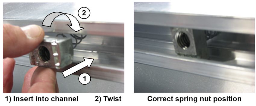
2. Insert spring nuts into the left and right cabinet channels. Twist the spring nuts until
they are perpendicular to the channel (Figure 5).
Figure 5: Spring Nut Insertion (Vertical)
Mechanical Installation
4Note: Each vertical POSITION cabinet section will typically require two horizontal
beams fastened to the main vertical structure. Cabinets are attached to
each horizontal beam with four spring nuts and two clamping angles.
3. Position a spring nut on the top and bottom of each horizontal beam.
4. Screw a threaded rod into each of the spring nuts as far as it will go.
5. Slide clamping angles over the ends of the rods and loosely install the washers and
nuts.
6. Make final adjustments in the positioning of the display section to ensure it is flush and
level.
7. Ensure the threaded rods are perpendicular to the display, and then tighten all of the
1/2" hex nuts (Figure 6).
8. Repeat Steps 1-7 for all display sections.
Vertical
Clamping Beam
Angle
Display Horizontal
Section Beam
Spring Nuts
(Inside Channel) 1/2" Flat Washer,
Lock Washer, Nut,
& Threaded Rod
Figure 6: Spring Nut Mounting, Side View
Mechanical Installation
5Mounting Horizontal Displays
Two standard mounting methods are available for horizontal displays, including variable
position sections below vertical pylons and time/lap sections above vertical pylons. Each
method requires spring nuts to be inserted into the rear channel of the display cabinet.
Note: Do not use lubrication on any mounting hardware or the warranty will be void!
1. Insert spring nuts into the top and bottom cabinet channels. Twist the spring nuts until
they are perpendicular to the channel (Figure 7).
2. Measure the beam spacing and position a spring nut on either side of the beams.
Each display section requires four spring nuts per beam (two at the top and two at
the bottom).
Figure 7: Spring Nut Insertion
Once the spring nuts are in place, refer to the appropriate section that follows for the
type of mounting hardware provided with the display.
Clamping Angles
Reference Drawings:
P1647; Pole Mounting Options......................................................................... DWG-1048184
Use this mounting method to mount a display to I-beams or any beam/pole that does
not have flanges. Mounting hardware includes spring nuts; rear clamping angles; 1/2-13
x 24" threaded rods; and 1/2" nuts, flat washers, and lock washers. Refer to Figure 8 and
DWG-1048184 in Appendix B.
Note: The threaded rods do not pass through the beams; they run along both sides.
1. Screw a threaded rod into each of the spring nuts as far as it will go.
2. Position a display section at the front of the beams with the threaded rods extending
from the rear of the spring nuts, straddling the beams.
3. Lift the display section to the desired height.
4. Slide clamping angles over both rods, and then loosely install the washers and nuts.
5. Make final adjustments to the display section position to ensure it is flush and level,
and then firmly tighten all of the 1/2" hex nuts.
6. Repeat Steps 1-5 for all display sections.
Mechanical Installation
61/2" Flat Washer,
Lock Washer, Nut,
& Threaded Rod
Display Vertical
Section Beam
Clamping Angle
Spring Nut
Figure 8: Clamping Angle Mounting, Side View
I-Beam Clamps (Drag Racing)
Reference Drawings:
P1647; I-Beam Clamp Mounting...................................................................... DWG-1052565
P1647; DSA I-Beam Clamp Mounting.............................................................. DWG-1064893
Use this mounting method to mount a display to I-beams with a flange thickness of 1/4" –
3/4". If the flange is thicker than 3/4", longer bolts will be required at added expense.
Mounting hardware includes spring nuts, I-beam clamps, 1/2-13 x 3" bolts, 1/2" flat
washers, and 1/2" lock washers. Refer to Figure 9 and DWG-1052565 in Appendix B.
1. Position a display section at the front of the beams, and lift it to the desired height.
2. Slide a lock washer, flat washer, and I-beam clamp onto the bolt, and loosely screw
the bolt into the spring nut.
3. Position each I-beam clamp assembly as close to the I-beam flanges as possible.
4. Make final adjustments to the display section position to ensure it is flush and level,
and then firmly tighten all of the bolts.
5. Repeat Steps 1-4 with all display sections.
Note: For DSA (California) approved mounting to I-beams, refer to DWG-1064893.
Mechanical Installation
7Display
Cabinet
Beam Spring Nut
I-Beam Clamp
1/2" Flat Washer
1/2" Lock Washer
1/2-13 x 3" Bolt
Figure 9: I-beam Clamp Mounting, Rear Rotated View
Go-Kart Display Mounting
Note: Do not use lubrication on any mounting hardware or the warranty will be void!
Reference Drawings:
Scoreboard Mounting....................................................................................... DWG-1130246
Mounting hardware includes mounting channels; rear clamping angles; 1/2-13 x 15"
threaded rods; and 1/2" square nuts, hex nuts, and lock washers. Refer to Figure 10 and
DWG-1130246 in Appendix B.
Note: The threaded rods do not pass through the beams; they run along both sides.
1. Position the display at the front of the beams, and lift it to the desired height.
2. Place a mounting channel against the upper rear flange of the cabinet next to each
beam.
3. Using the mounting channel as a template, drill two 9/16" holes in the upper rear
flange of the cabinet where the rods will pass through. The rods should be as close to
the beam as possible.
4. Place 1/2" square nuts inside the mounting channel, and thread the rods through the
rear flange of the cabinet and the mounting channel.
5. Slide clamping angles over the other ends of both threaded rods, and then loosely
install the washers and nuts.
6. Make final adjustments to the display position to ensure it is flush and level, and then
firmly tighten all of the 1/2" hex nuts.
7. Repeat Steps 2-6 for the lower rear flange of the cabinet for every beam.
Mechanical Installation
81/2" Square Nut 1/2-13 X 15" Threaded Rod
Mounting Clamping Angle
Channel
1/2" Hex Nut
1/2" Lock Washer
Display
Beam
Cabinet
Figure 10: C-channel Mounting Method, Side View
CH-3105
The CH-3105 horizontal 4-section go-kart display can be mounted to beams with the use
of special brackets that both hold the cabinet to the beams and connect two sections
together. The CH-3105 can also be mounted to a wall via holes in the sides of the
cabinet. Due to the variety of wall materials used in racing facilities, Daktronics cannot
anticipate a customer's individual installation needs or provide mounting hardware
suitable for every installation. Choose a method of installation that will safely support the
display weight.
Refer to the installation drawings attached to the CH-3105 product specification sheet
listed in Appendix A for more information about beam and wall mounting.
Ad Panel Mounting
Note: Do not use lubrication on any mounting hardware or the warranty will be void!
Unistrut Attachment
1. Using the backup channel as a
3/8-16 x 1" Bolt
template, drill four 7/16" holes in the
upper and lower rear flanges of the 3/8" Lock Washer
ad panel where the beams will be
located. 3/8" Flat Washer
Unistrut
Note: Try to ensure that the two
center holes will be within the
Backup Channel
width of the beam. 3/8-16 Square Nut
2. If the ad panel has backsheets,
remove them as needed to access the
ad panel interior.
3. Attach the piece of unistrut to the ad
panel with the included hardware, as
shown in Figure 11.
Figure 11: Unistrut Attachment, Side View
Mechanical Installation
94. If any backsheets were removed, put them back on at this time.
5. Place spring nuts into the unistrut. Twist the spring nuts until they are perpendicular to
the unistrut channel. Refer to Figure 7 from Mounting Horizontal Displays (p.6).
Note: Ad panel cabinets require four spring nuts per beam (two at the top and two
at the bottom).
Once the unistrut is attached and the spring nuts are in place, refer to the appropriate
section that follows for the type of mounting hardware provided with the ad panel.
Clamping Angles
Reference Drawings:
Ad Panel Pole Mounting................................................................................... DWG-1052388
Mounting hardware includes rear clamping angles; 1/2-13 x 24" threaded rods; and 1/2"
nuts, flat washers, and lock washers. Refer to Figure 12 and DWG-1052388 in Appendix B.
Note: The threaded rods do not pass through the beams; they run along both sides.
1. Screw a threaded rod into each of the spring nuts as far as it will go.
2. Position the ad panel at the front of the beams, and lift it to the desired height.
3. Slide clamping angles over both rods, and then loosely install the washers and nuts.
4. Make final adjustments to the ad panel position to ensure it is flush and level, and
then firmly tighten all of the 1/2" hex nuts.
Clamping Angle
Spring Nut 1/2" Threaded Rod
Ad Panel Beam 1/2" Flat Washer,
Lock Washer, & Nut
Figure 12: Ad Panel Clamping Angle Mounting, Side View
Mechanical Installation
10I-Beam Clamps (Drag Racing)
Reference Drawings:
Ad Panel I-beam Clamp Mounting................................................................. DWG-1052539
Ad Panel DSA I-beam Clamp Mounting........................................................ DWG-1064894
Use this mounting method to mount an ad panel to I-beams with a flange thickness of
1/4" – 3/4". If flange is thicker than 3/4", longer bolts will be required at added expense.
Mounting hardware includes I-beam clamps, 1/2-13 x 3" bolts, 1/2" flat washers, and 1/2"
lock washers. Refer to Figure 13 and DWG-1052539 in Appendix B.
1. Position the ad panel at the front of the beams, and lift it to the desired height.
2. Slide a lock washer, flat washer, and I-beam clamp onto the bolt, and loosely screw
the bolt into the spring nut.
3. Position each I-beam clamp assembly as close to the I-beam flanges as possible.
4. Make final adjustments to the ad panel position to ensure it is flush and level, and
then firmly tighten all of the bolts.
Note: For DSA (California) approved mounting to I-beams, refer to DWG-1064894.
Ad Panel
with Unistrut
Spring Nut
Beam
I-Beam Clamp
1/2" Flat Washer
1/2" Lock Washer
1/2-13 x3" Bolt
Figure 13: Ad Panel I-beam Clamp Mounting, Rear Rotated View
Mechanical Installation
113 Electrical Installation
CAUTION: Only qualified individuals should perform routing and termination to the
display. Electrical contractors are responsible for ensuring that all electrical work meets
or exceeds local and national codes. Daktronics engineering staff must approve all
changes or the warranty will be void.
Electrical installation consists of the following processes:
• Providing power and ground to a disconnect near the display.
• Routing power and ground from the main disconnect to the display power/signal
enclosure.
• Routing the control signal cable from the control location to the display location
and/or installing the wireless radio receiver.
Installation Overview
Figure 14 illustrates a wired setup between a vertical (Auto Racing) display and
controller. Daktronics part numbers are shown in parentheses.
Vertical Beams
Pin Color Function
tip red signal +
ring black signal -
not used at
shaft green
control end
To Display
Vertical Horizontal
Structure Beams J-Box,
1/4" Phone Jack;
Outdoor: (0A-1091-0227)
Indoor: (0A-1009-0038)
Power & Signal
Signal Cable:
Terminated Inside
10' (W-1340)
Lockable Power Bottom Display Section 20' (W-1236)
Distribution / 30' (W-1238)
Disconnect 50' (W-1237)
Signal Cable: 2 Pair, J1, J2,
Grounding Wire 22 AWG (W-1234); or J3
Max 2000'
To Control Location
To Main Power Source
- See Specfications All Sport Controller
Grounding Rod
Figure 14: Vertical Display Wired Installation (AR Shown)
Note: Power, signal, and control are similar for go-kart displays, while mounting differs.
Electrical Installation
12Figure 15 illustrates a typical wireless setup between a vertical (Auto Racing) display and
controller.
DAKTRONICS
TIME LAP
POS
Up to 1500' away with
1
direct line of sight
2
3
All Sport Controller
with Radio Option
4
Radio
Receiver
5
Lockable Power
Power Terminated Distribution /
Inside Display Disconnect
(Through Rear Conduits
of Bottom Section)
Grounding Wire
To Main Power Source
- See Specfications
Grounding Rod
Figure 15: Vertical Display Wireless Installation (AR Shown)
Electrical Installation
13Figure 16 illustrates a typical wired setup between a horizontal (Drag Racing) display and
controller. Daktronics part numbers are shown in parentheses.
Display Rear
Power is terminated inside
both display sections;
Signal is terminated inside bottom
section and re-driven into top section
Lockable Power
Distribution /
Disconnect
Concrete Signal Cable: 2 Pair,
Footings Grounding Wire 22 AWG (W-1234);
Max 2000'
To Control Location
To Main Power Source
- See Specfications
Grounding Rod
J-Box, 1/4" Phone Jack;
Outdoor: (0A-1091-0227)
Indoor: (0A-1009-0038)
To Display Signal Cable:
J1, J2, 10' (W-1340)
or J3 20' (W-1236)
Pin Color Function 30' (W-1238)
tip red signal + 50' (W-1237)
ring black signal -
not used at
shaft green
control end All Sport Controller
Figure 16: Horizontal Display Wired Installation (DR Shown)
Note: Multi-section horizontal displays require internal power/signal interconnects
between sections, and prior to June 2016, Drag Racing displays required
PVC pipes to route power and signal between sections; refer to Power/Signal
Connections Between Sections (p.20).
Electrical Installation
14Figure 17 illustrates a typical wireless setup between a horizontal (Drag Racing) display
and controller.
Up to 1500' away with
Signal in Conduit
direct line of sight
from Bottom to
Top Section
(Drag Racing
Displays Only)
DAKTRONICS
All Sport Controller Radio
Power Terminated
with Radio Option Receiver
Inside Display
Lockable Power Through Rear
Grounding Wire
Distribution /
Disconnect
Concrete
To Main Power Source Footings
- See Specfications
Grounding Rod
Figure 17: Horizontal Display Wireless Installation (DR Shown)
Note: Radio-controlled Drag Racing displays require signal wire in conduit from the
bottom section up into the top section; refer to Wired Signal Connection (p.18).
Multi-section horizontal displays require internal power/signal interconnects
between sections, and prior to June 2016, Drag Racing displays required
PVC pipes to route power and signal between sections; refer to Power/Signal
Connections Between Sections (p.20).
Power
Only qualified individuals should complete the electrical installation; untrained personnel
should not attempt to install these displays or any of the electrical components. Improper
installation can seriously damage the equipment and be hazardous to personnel.
Refer to the specification label on the display (Figure 1), the label inside the display
(Figure 19), or the product specification sheets shipped with it (and listed in Appendix A),
to determine maximum power requirements. Ensure all external overcurrent protection
meets all local and national electrical codes and is appropriately sized to the load it is
terminating. Failure to meet wiring and overcurrent protection device requirements will
void the warranty.
Note: Ensure the display is on a dedicated circuit. This will prevent loss of critical race/
event information that may otherwise occur if another component on the same
circuit should fail.
Electrical Installation
15Grounding
All components of a display system – including but not limited to displays, control
equipment, and connected peripheral equipment – must be electrically grounded.
Only qualified individuals may perform electrical work, including verification of ground
resistance. Daktronics is not responsible for improper grounding or damage incurred as a
result of improper grounding.
Grounding methods must meet the provisions of all applicable local and national codes.
Inspect and verify all grounding methods meet the provisions of all applicable local and
national codes.
Proper grounding is necessary for reliable equipment operation and general electrical
safety. Failure to properly ground the display system may void the warranty, disrupt
operation, damage equipment, and cause bodily harm or death.
There are two types of power installation: installation with ground and neutral conductors
provided, and installation with only a neutral conductor provided. These two power
installations differ slightly, as described in the following subsections.
Installation with Ground and Neutral Conductors Provided
For this type of installation, the power circuit must contain an isolated earth-ground
conductor. In this circumstance, do not connect neutral to ground at the disconnect or
at the display as this would violate electrical codes and void the warranty.
Use a disconnect so that all ungrounded lines can be disconnected. The local and
national electrical codes may require using a lockable power disconnect at or within
sight of the display.
Installation with Only a Neutral Conductor Provided
Installations where no grounding conductor is provided must comply with local and
national electrical codes. If the installation meets all requirements, observe the following
guidelines:
• Connect the grounding electrode cable at the local disconnect, never at the display
driver/power enclosure.
• Use a disconnect that opens all of the ungrounded phase conductors.
Lightning Protection
The use of a disconnect near the display location to completely cut all current-carrying
lines significantly protects the circuits against lightning damage. Local and national
electrical codes may also require it. In order for this system to provide protection, the
power must be disconnected when the display is not in use.
The control console also should be disconnected from power and from the signal
junction box when the system is not in use. The same surges that may damage the
display components can also damage the console’s circuitry.
Electrical Installation
16Connection
Power and signal cables are routed into the display from the rear via separate conduits.
All power and signal wiring terminates at the primary driver enclosure. Note that systems
with radio control typically only require signal wiring for backup purposes.
Refer to the component location drawings attached to the product specification sheets
listed in Appendix A for precise power/signal termination location for each model.
1. Look for a warning label similar to Figure 18
PRIMARY
to locate the access panel to the driver
DRIVER IS LOCATED
enclosure. BEHIND THIS PANEL
2. Remove the screws or loosen the latches to
THIS DEVICE COMPLIES WITH PART 15 OF THE FCC RULES. OPERATION IS SUBJECT TO
THE FOLLOWING TWO CONDITIONS: (1) THIS DEVICE MAY NOT CAUSE HARMFUL
INTERFERENCE AND (2) THIS DEVICE MUST ACCEPT ANY INTERFERENCE RECEIVED,
open the access door panel. INCLUDING INTERFERENCE THAT MAY CAUSE UNDESIRED OPERATION
3. Remove the metal cover of the driver Figure 18: Power Warning Label
enclosure by lifting it up, then back and
down to expose the driver components.
4. Connect the power wires coming through the rear of the display to the power
terminal blocks, as shown in Figure 19.
Driver Enclosure Power Terminal Blocks
Factory Wiring
T
D
K
H
N
BL
W
G
POWER
NEUTRAL
GROUND
LINE
H
D
C
B
E
A
F 0 1
9 8 7
F 0 1
2
6
3
4
5
Field Wiring
L
E 2
D 3
C 4
B 5
A9 6
8 7
SUITABLE FOR SERVICING ONLY WHEN DE-ENERGIZED
PUET FAIRE L'OBJET D'UN ENTRETIEN UNIQUEMENT S'IL EST HORS TENSION
CAUTION: TURN OFF ALL INTEGRAL DISCONNECTS BEFORE
CONFORMS TO SERVICING.
UL STD 48 ATTENTION: METTRE HORS TENSION TOUS LES SECTIONNEURS
CERTIFIED TO CSA INTEGRS AVANT D'ENTREPRENDRE LE DEPANNAGE.
17800 STD C22.2 NO. 207 INSTALLER A L'EXTERIEUR
OUTDOOR USE
DAKTRONICS 201 DAKTRONICS DR. BROOKINGS, SD PHONE 800-325-8766
Figure 19: Driver Enclosure & Power Terminal Blocks (Cover Removed)
Some displays do not receive power via terminal block. Instead, an interconnect harness
routes from the nearest display section. Refer to Power/Signal Connections Between
Sections (p.20).
Note: If a power receptacle is needed to operate the control console at the display
for troubleshooting, an installation electrician must provide an outlet close to the
disconnect box specifically for this purpose.
Electrical Installation
17Power-On Self-Test (POST)
The display performs a self-test each time that power is turned on and the control
console is powered off or not connected. If the control console is connected and
powered on, the self-test does not run, and data from the control console appears on
the display after a few seconds. Each self-test pattern will vary depending on the model,
the number of drivers, and types of digits. Figure 20 shows an example of the LED bar test
pattern that each digit performs.
Figure 20: Digit Segment POST
Wired Signal Connection
Copper Signal
Route copper signal cable through the
conduit knockout on the rear of the display
to the signal surge arrestor card (Figure 21),
located in the primary driver enclosure.
SIGNAL OUT
At the SIGNAL IN terminal block, connect
red signal wire to positive (+) and black SHLD
signal wire to negative (–).
SHLD
-
Note: Ensure shield (silver) wire is properly
+
connected to the SHLD terminal.
SHLD
To connect signal to additional nearby SHLD
displays, such as from the bottom (MPH) -
section to the top (Elapsed Time) section +
of a Drag Racing display, route signal wire
in conduit from SIGNAL OUT of the signal
SIGNAL IN
surge arrestor card in the primary display to Figure 21: Signal Surge Arrester Card
SIGNAL IN on the signal surge arrestor card
in the secondary display.
At a minimum, single-pair, shielded cable, 22 AWG (part # W-1077) is recommended.
Two-pair shielded cable (part # W-1234) is preferred.
Electrical Installation
18Fiber Optic Signal
Route fiber optic signal cable through the
conduit knockout on the rear of the display.
The fiber optic cable is terminated to a male
ST-type connector and plugged into the J3
jack on the fiber card (Figure 22), located in SIGNAL OUT
the primary driver enclosure. SHLD
SHLD
A minimum cabling of multi-mode, 62.5/125
-
um, and 2-core fiber cable is recommended +
(part # W-1242). This method requires a
signal converter between the All Sport
console’s scoreboard output and the fiber
optic cable (not provided by Daktronics).
To connect signal to additional nearby
displays, such as from the bottom (MPH)
section to the top (Elapsed Time) section of SIGNAL IN
a Drag Racing display, route *copper* signal
wire in conduit from SIGNAL OUT of the fiber Figure 22: Fiber Card
card in the primary display to SIGNAL IN on
the signal surge arrestor card in the secondary display.
Multiple Driver Connections
Some display models require multiple drivers that use a primary/secondary driver system.
Primary and secondary drivers function identically, but secondary enclosures lack the
power termination block and signal surge arrestor (or fiber) card. When one section has
multiple drivers, they simply plug into one another, and this is done at the factory. Drivers
between sections, however, require additional on-site connection. Refer to Power/Signal
Connections Between Sections (p.20).
Wireless Signal Connection
All Sport Control
A wireless radio system requires a radio receiver plugged into the 6-pin J21 jack on the
primary driver and mounted internally to the front panel of the display. An All Sport
control console equipped with radio transmitter is also required. For more information,
refer to the Gen VI Radio Installation Manual (DD2362277), provided with the receiver unit
and available online at www.daktronics.com/manuals.
Radio Settings
With an All Sport radio receiver installed, watch for the radio Broadcast settings (“b1”)
and Channel settings (“C1”) during the Power-On Self-Test (POST) (p.18).
These values must match the settings in the control console.
RADIO SETTINGS
Refer to the controller screen at right and the manual listed in
BCAST 1 CHAN 01
Display Controllers (p.2).
If the radio receiver channel and broadcast settings match those set in the console but
the console does not control the display, there may be radio interference. This can occur
when a nearby display also uses radio control. In this case, change the settings of the
wireless radio receiver inside the display and in the console as described in the radio
control manuals.
Electrical Installation
19Power/Signal Connections Between Sections
Refer to the Specifications drawings attached to the product specification sheets listed in
Appendix A for exact driver locations when connecting multiple display sections.
Vertical Displays
Open the appropriate access panel on the bottom display section to locate the coiled
bundle of interconnect cable coming from the driver, then route and connect the
cables as described below and shown in Figure 23.
Note: Additional panels may be opened for easier access when routing the cable.
1. Starting with the bottom section, disconnect and discard the harness with 5-pin plug
(P42) from the driver and terminal block; this is where external power and signal will
be terminated as described in Power (p.15) and Wired Signal Connection (p.18).
2. Locate the interconnect cable with the 5-pin jack (J43) toward the top of the bottom
section. Route this cable up through the hole in the top of the cabinet and into the
next section, then connect the jack to the mating 5-pin plug (P42).
3. Repeat Step 2 for each display section, moving upward until they are all connected.
Primary
Time/Lap Driver
Section
P42
J43
Position
Section
Primary
Driver
If Bottom Section:
P42
Disconnect and discard
J43 this harness, and then
terminate external
Power & Signal
Figure 23: Power/Signal Connections
Horizontal Displays (AR-2402 + AR-2407)
These displays are connected via a single power/signal interconnect cable between a
driver in the lower section (AR-2407) and a driver in the upper section (AR-2402).
1. On the lower section cabinet, open the appropriate access panel to locate the
bundle of interconnect cable with 5-pin plug (P42) coming from the driver.
2. Route the interconnect cable up through the hole in the top of the lower section
cabinet and up through the hole in the bottom of the upper section cabinet, and
then connect it to the mating 5-pin jack (J42) coming from the driver.
Electrical Installation
20CH-3105
The CH-3105 is composed of four sections. Power and signal are terminated in the top
section, and then interconnect cables route down from section to section. Connect
the J51 jack in the top section to the mating P51 plug in the section below it. Continue
making these connections until all sections have power and signal.
CH-3001 and CH-3006
Since these displays have no driver, they require individual digit harnesses to be routed
down into the Position 1-5 display and connected to the appropriate jacks in the
driver. Refer to the Component Location drawing attached to the spec sheets listed in
Appendix A.
Drag Racing Displays
PVC Adaptor
• For drag racing displays built after (Inside Display)
June 2016, power is terminated
in each section; refer to Power Upper
(p.15). Signal is terminated in the Display
bottom section and re-driven into Section
the top section; refer to Wired Signal (ET)
Connection (p.18).
• For drag racing displays built before
June 2016, PVC pipes were required
to route several digit harnesses
PVC Pipe Insides of Displays
between sections as described with Adaptor Shown for Clarity
below.
Elapsed Time (ET) sections do not have
a terminal block to receive power and
signal. Instead, individual digit harnesses
must be routed into the MPH section Lower
and connected to the appropriate jacks Display
Section
on the driver(s). PVC pipes are used as
(MPH)
conduits for the digit harnesses between
display sections. Refer to Figure 24 and Locknut
the instructions below.
Digit Harnesses
(to Driver)
Note: The Elapsed Time section will
always be located above the Figure 24: Interconnect Between Display Sections
MPH section, no more than 24"
(610 mm) away.
1. Route the wiring harnesses from the bottom of the elapsed Time Section through a
PVC pipe, making sure the end with the 2" (51 mm) adaptor is pointing down.
2. Insert the PVC pipe up into a hole in the bottom of the Elapsed Time section. Inside is
another 2" (51 mm) adaptor with the 9-pin harness pre-routed through it. Connect this
adaptor to the PVC pipe.
3. For the DR-3683 and DR-4883, repeat Steps 1–2 for the other interconnect conduit.
4. Route the harnesses down through the hole(s) in the top of the MPH section. Make
sure the threaded end of the 2" (51 mm) adaptor is just inside the top of this section
as well.
Electrical Installation
215. Once the harnesses are inside the bottom section, slip a 2" (51 mm) locknut over the
harnesses, and screw it onto the adaptor, securing the PVC pipe to the top of the
display cabinet.
6. Connect the 9-pin plugs of the digit harnesses to the mating jacks on the driver(s).
Refer to the Component Location drawings attached to the spec sheets listed in
Appendix A for exact driver locations and digit designations.
Note: On the DR-4882, there is also a power supply next to the driver enclosure.
Connect the 2-pin plugs from each digit to the mating power supply jacks.
Optional Win Light Installation
The optional drag racing win light is designed for mounting below the miles per hour
section, but it can be flipped over and mounted atop the timing section. DWG-186500 in
Appendix B provides examples of mounting to both locations. Refer to the steps below
and Figure 25 for further mounting information.
1. Determine where the win light will be mounted on the existing display.
2. Cut or drill a 2" (51 mm) hole in the bottom (or top) of the existing racing display that
lines up with the hole in the win light cabinet.
3. Route the 25' (7.6 m) harness through the hole in the win light cabinet into the main
display via the hole created in step 2.
4. Access the primary (A1) display driver by opening the appropriate digit/access
panel, and connect the 9-pin plug from the win light to the J10 jack. Refer to the
Component Location drawings attached to the spec sheets listed in Appendix A for
exact driver location of a particular model.
5. Using the six (6) predrilled mounting holes on the outside flange of the win light
cabinet, attach it to the main display cabinet with sheet metal screws, bolts, or rivets
(not provided by Daktronics).
Primary Harness
Driver J10 (from Win Light)
Mounting Hardware
(by Customer)
Figure 25: Win Light Installation (Not to Scale)
Electrical Installation
224 Daktronics Exchange and Repair & Return
Programs
Exchange Program
The Daktronics Exchange Program is a service for quickly replacing key components
in need of repair. If a component fails, Daktronics sends a replacement part to the
customer who, in turn, returns the failed component to Daktronics. This decreases
equipment downtime. Customers who follow the program guidelines explained below
will receive this service.
Before contacting Daktronics, identify these important numbers:
Model Number: ______________________________________________________________________
Assembly Number: ___________________________________________________________________
Job/Contract Number: ________________________________________________________________
Date Manufactured/Installed: _________________________________________________________
Daktronics Customer ID Number: ______________________________________________________
To participate in the Exchange Program, follow these steps:
1. Call Daktronics Customer Service.
United States & Canada: 1-800-DAK-TRON (325-8766)
Outside the U.S. & Canada: +1-605-275-1040
2. When the new exchange part is received, mail the old part to Daktronics.
If the replacement part fixes the problem, send in the problem part being replaced.
a. Package the old part in the same shipping materials in which the replacement
part arrived.
b. Fill out and attach the enclosed UPS shipping document.
c. Ship the part to Daktronics.
3. The defective or unused parts must be returned to Daktronics within 5 weeks of initial
order shipment.
If any part is not returned within five (5) weeks, a non-refundable invoice will be
presented to the customer for the costs of replenishing the exchange parts inventory
with a new part. Daktronics reserves the right to refuse parts that have been
damaged due to acts of nature or causes other than normal wear and tear.
Daktronics Exchange and Repair & Return Programs
23Repair & Return Program
For items not subject to exchange, Daktronics offers a Repair & Return Program. To send
a part for repair, follow these steps:
1. Call Daktronics Customer Service.
United States & Canada: 1-800-DAK-TRON (325-8766)
Outside the U.S. & Canada: +1-605-275-1040
2. Receive a case number before shipping.
This expedites repair of the part.
3. Package and pad the item carefully to prevent damage during shipment.
Electronic components, such as printed circuit boards, should be placed in an
antistatic bag before boxing. Daktronics does not recommend using packing
peanuts when shipping.
4. Enclose:
• name
• address
• phone number
• the case number
• a clear description of symptoms
5. Ship to:
Daktronics Customer Service
[Case #]
201 Daktronics Drive, Dock E
Brookings, SD 57006
Daktronics Warranty & Limitation of Liability
The Daktronics Warranty & Limitation of Liability is located at the end of this manual.
The Warranty is independent of Extended Service agreements and is the authority in
matters of service, repair, and operation.
Daktronics Exchange and Repair & Return Programs
24A Specifications
All of the product specification sheets for the displays in this manual are listed below.
Product-specific installation and component location drawings are included with each
spec sheet.
Note: Refer to Figure 1 to determine a display's model number.
Viewing Product Specifications Online:
If a specification sheet is incorrect or missing, they are all available for download online.
• When viewing the digital version of this manual, simply click a link below to open it.
• When referencing the printed version of this manual, open an Internet browser and
go to www.daktronics.com/Web%20Documents/HSPR-Documents/DD#######.pdf
(replace “DD#######” with one of the Spec Sheet numbers shown below).
Model Spec Sheet Model Spec Sheet
AR-1522 DD2910635 AR-2429 DD2910651
AR-2401 DD2910636 CH-3001 DD2910652
AR-2404 DD2910639 CH-3002 DD2910653
AR-2402 DD2910640 CH-3003 DD2910654
AR-2407 DD2954081 CH-3004 DD2910655
AR-2421 DD2910641 CH-3006 DD2910656
AR-2422 DD2910643 DR-2482
DD2910657
AR-2423 DD2910644 DR-2483
AR-2424 DD2910645 DR-3682
DD2910658
AR-2426 DD2910647 DR-3683
AR-2427 DD2910648 DR-4882
DD2910660
AR-2428 DD2910650 DR-4883
Specifications
25This page intentionally left blank.
B   Reference Drawings
    Refer to Resources (p.1) for information regarding how to read the drawing number.
    Any contract-specific drawings take precedence over these general drawings.
    Reference Drawings:
       Attachment; Win Light Display........................................................................... DWG-186500
       P1647; Pole Mounting Options......................................................................... DWG-1048184
       Ad Panel Pole Mounting................................................................................... DWG-1052388
       Ad Panel I-beam Clamp Mounting................................................................. DWG-1052539
       P1647; I-beam Clamp Mounting...................................................................... DWG-1052565
       P1647; DSA I-Beam Clamp Mounting.............................................................. DWG-1064893
       Ad Panel DSA I-beam Clamp Mounting........................................................ DWG-1064894
       Scoreboard Mounting....................................................................................... DWG-1130246

                                           Reference Drawings
                                                   27
This page intentionally left blank.
1/2" THREADED ROD
                                                VERTICAL BEAM

           SPRING NUT
                                                                                            1/2" FLAT WASHER
                                                            REAR MOUNTING ANGLE           LOCK WASHER, AND NUT

                                                                  1/2" THREADED ROD     REAR MOUNTING ANGLE

                                                                                               VERTICAL BEAM

                                                         1/2" FLAT WASHER,                            SPRING NUT
                                                       LOCK WASHER, AND NUT

 SCOREBOARD
                              SIDE VIEW
                                                                                                                                                    DISPLAY

                                                                                                                                FRONT OF DISPLAY

                                                                                                                                                 TOP VIEW
                                                                                                                                                SCALE 1/10

                                                                                                                     ***CRITICAL***
                                                                                                               DO NOT USE ANY LUBRICANT
                                                                                                              ON ANY MOUNTING HARDWARE
                                                                   ***CRITICAL***
                                                                MAKE SURE SPRING NUT                          OR WARRANTY WILL BE VOIDED
                                                                IS TURNED TO VERTICAL
                                                                    POSITION INSIDE
                                                                 SCOREBOARD CHANNEL
                                                                                                                                                                                 PJS
                                                                                         04         22 DEC 15              PER EC-22871; ADDED LUBRICANT WARNING
                                                                                                                                                                                18704

                                                                                         03         03 JULY 13                     ADDED STRUCTURAL NOTE                         TTF

                                  EXTRA THREADED ROD                                     02         20 SEP 12          PER EC-7114; REMOVED CHAMFER FROM 0M-133259               LMG

                                     CAN BE CUT OFF
                                                                                                                                  REPLACED VERTICAL I-BEAM
                                                                                         01         06 OCT 11                                                                   JAVA
                                                                                                                                  WITH 6" X 6" SQUARE TUBE
                               REAR ISOMETRIC VIEW                                       REV          DATE:                                                                      BY:

STRUCTURAL NOTES:                                                                                                THE CONCEPTS EXPRESSED AND DETAILS SHOWN ON THIS DRAWING   THIRD ANGLE PROJECTION
- BOLT TORQUE: 30 FT-LB                                                                                            ARE CONFIDENTIAL AND PROPRIETARY. DO NOT REPRODUCE BY
                                                                                                                     ANY MEANS WITHOUT THE EXPRESS WRITTEN CONSENT OF
                                                                                                                      DAKTRONICS, INC. OR ITS WHOLLY OWNED SUBSIDIARIES.
                                                                                                                            COPYRIGHT 2016 DAKTRONICS, INC. (USA)
NOTES:
- THREADED RODS RUN ALONG BOTH SIDES OF BEAM                                            PROJECT:     OUTDOOR SCOREBOARDS
- RODS DO NOT PASS THROUGH THE FLANGES OF THE BEAM                                         TITLE:    P1647; POLE MOUNTING OPTIONS
- NO DRILLING NECESSARY                                                                    DATE:     22-DEC-15     DIM UNITS: INCHES [MILLIMETERS]                             SHEET        REV

- MAKE SURE SPRING NUT IS PERPENDICULAR TO CHANNEL                                        SCALE:     1/5              DO NOT SCALE DRAWING                                    1 OF 1         04
  OPENING ON SCOREBOARD                                                                              DOPPELT
                                                                                                                                                                       1048184
                                                                                         DESIGN:                       JOB NO.   FUNC - TYPE - SIZE
                                                                                         DRAWN:      DOPPELT         P1647        E - 10 - A
You can also read


