MSI-3460 Operator's Manual
←
→
Page content transcription
If your browser does not render page correctly, please read the page content below
MSI-3460
                    Challenger 3

Operator’s Manual

                     152161 Rev C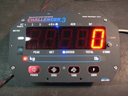
Contents
1.0      Introduction ...........................................................................1
            1.1 Safety ................................................................................... 2
            1.2 General Information ............................................................ 4
                  1.2.1       User Guide & MSI-3460 Conventions .................................4
            1.3 MSI3460 Annunciators ........................................................ 5
            1.4 Specifications ...................................................................... 6
            1.5 Features ............................................................................... 8
            1.6 Options ................................................................................ 8
            1.7 Unpacking ........................................................................... 8
            1.8 Assembly ............................................................................. 9
            1.9 Battery Pack ...................................................................... 10
            1.10Battery Charger ................................................................ 11
2.0      Operation .............................................................................12
            2.1 Power ................................................................................. 12
            2.2 Zero ................................................................................... 12
            2.3 Tare .................................................................................... 13
3.0      User Defined Function Keys .................................................14
4.0      Configuration .......................................................................16
            4.1   Menu Map ......................................................................... 16
            4.2   Function Keys ................................................................... 17
            4.3   Auto- Off ............................................................................ 18
            4.4   Sleep .................................................................................. 19
            4.5   Display Brightness ............................................................ 20
            4.6   Set Points .......................................................................... 21
            4.7   Total Mode ........................................................................ 23
            4.8   Units ................................................................................... 24
            4.9   Filter Setup ........................................................................ 25
5.0      Calibration ...........................................................................26
            5.1   Initial Calibration ............................................................... 29
            5.2   Guidelines for Capacity and Resolution .......................... 30
            5.3   C-Cal Calibration ............................................................... 31
            5.4   Calibration Setup Menu .................................................... 34
            5.5   Standard ............................................................................ 34
            5.6   Auto Zero Maintenance .................................................... 35

                          Technical training seminars are available through Rice Lake Weighing Systems.
                           Course descriptions and dates can be viewed at www.ricelake.com/training
                            or obtained by calling 715-234-9171 and asking for the training department.
      © 2013 Rice Lake Weighing Systems. All rights reserved. Printed in the United States of America.
                            Specifications subject to change without notice.
                    Rice Lake Weighing Systems is an ISO 9001 registered company.
                                       December 23, 2013 Rev B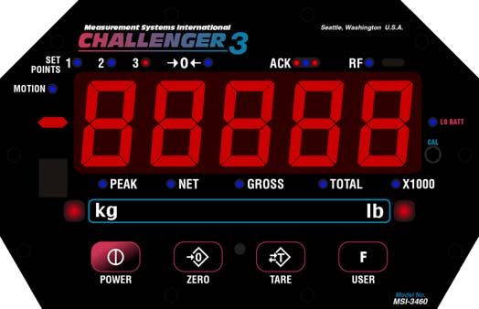
6.0    RF Remote Control Option ...................................................37
         6.1   Description ........................................................................ 37
         6.2   Functions ........................................................................... 37
         6.3   Setting the Transmitter Address ...................................... 37
         6.4   Setting the Receiver Address ........................................... 38
               6.4.1      Resetting the MSI-3460 RF Remote Receiver ..................38
         6.5 Contention and Jamming Considerations ....................... 38
         6.6 Battery Replacement ........................................................ 39
         6.7 RF Remote Control FCC Statement ................................. 39
7.0    RF Remote Display Option ...................................................40
         7.1 Introduction ....................................................................... 40
         7.2 Printer/Serial Output Setup .............................................. 41
               7.2.1      Control Modes .................................................................41
         7.3   Standard Print Strings ...................................................... 42
         7.4   802.15.4 RF Network Setup .............................................. 44
         7.5   FCC Statement (for 802.15.4 Option) ............................... 45
         7.6   RF Setup Procedure ......................................................... 45
         7.7   International RF CERTS (For 802.15.4 OPTION) .............. 47
8.0    Appendix ..............................................................................48
         8.1 Troubleshooting ................................................................ 48
               8.1.1      Service Counters ..............................................................50
         8.2 Software Update for use with SC3 PCA .......................... 51
         8.3 MSI-3460 Challenger 3 Dimensions ................................. 54
The MSI Limited Warranty ............................................................55

                       Rice Lake continually offers web-based video training on a growing selection
                          of product-related topics at no cost. Visit www.ricelake.com/webinars.

ii MSI3460 Operator’s Manual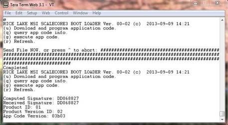
1.0 Introduction
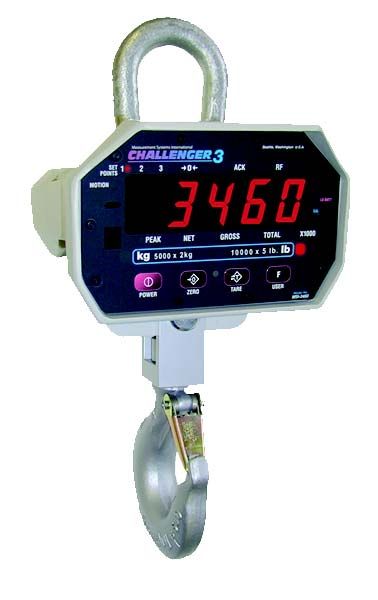
The MSI-3460 Challenger 3 is a combination of the sound and proven mechanical
design of the industry standard Challenger with today’s most advanced electronics. It
provide a superb feature set unmatched by any scale in its class or price range. The
multi-purpose hanging scale is ideal for situations in which headroom is at a
minimum. The MSI-3460 is versatile, reliable, accurate and easy to operate. The MSI-
3460 is designed to meet or exceed the requirements of all regulatory agencies. RF
remote control and remote display options are available to further enhance the safety
and usability of the MSI-3460.
Please take the time to read this manual completely through before attempting to use
the MSI-3460. Although designed for easy set up and use, a thorough understanding
of this manual will ensure that you receive the maximum benefit from the system.
If you have any questions or comments, please contact
Measurement Systems International
Phone (toll free): 1-800-874-4320
Manuals can be viewed or downloaded from the Measurement Systems
International site at:
www.msiscales.com.
Introduction 1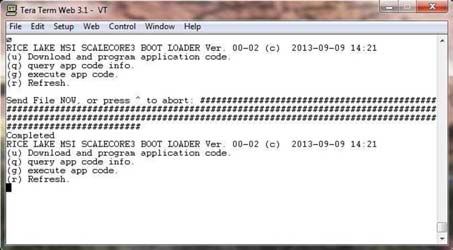
1.1 Safety
Safety Symbol Definitions:
                Indicates a potentially hazardous situation that, if not avoided,
     WARNING could result in serious injury or death, and includes hazards that
                are exposed when guards are removed.

                Indicates information about procedures that, if not observed,
     Important could result in damage to equipment or corruption to and loss of
                data.

                                  General Safety
                  Do not operate or work on this equipment unless you have read
                  and understand the instructions and warnings in the Installation,
                  Operators Manual. Contact any Measurement Systems
                  International dealer for replacement manuals. Proper care is
                  your responsibility.

                                      WARNING
               Failure to heed may result in serious injury of death.
DO NOT allow minors (children) or inexperienced persons to operate this unit.
DO NOT stand near the load being lifted as it is a potential falling hazard. Keep a
safe distance.
DO NOT use for purposes other then weight taking or dynamic load monitoring.
DO NOT use any load bearing component that is worn beyond 5% of the original
dimension.
DO NOT use the scale if any of the components of the load train are cracked,
deformed, or show signs of fatigue.
DO NOT exceed the rated load limit of the scale, rigging elements, or the lifting
structure.
DO NOT allow multi-point contact with the hook, shackle, or lifting eye of the
scale.
DO NOT allow high torque on the scale unless it is specifically designed for high
torque.
DO NOT make alterations or modifications to the scale or associated load bearing
devices.
DO NOT use improperly rated or sized shackles. Use only MSI recommended
shackles.
DO NOT remove or obscure warning labels.
For guidelines on the safe rigging and loading of overhead scales and
dynamometers, read the "MSI Crane Scale Safety and Periodic Maintenance
Manual" (available at www.msiscales.com).
Keep hands, feet and loose clothing away from moving parts.
There are no user serviceable parts within the MSI-3460. Any repairs are to be
performed by qualified service personnel only.

2   MSI-3460 Operator’s Manual
5 Digit 1.5/3.8mm
high brightness LED
weight display
Light Sensor for auto User programmable
brightness Control Wire sealable
function key calibration port
Figure 1-1. MSI-3460 Front Panel
Key Descriptions
Power Key - Turns the MSI-3460on and off.
POWER
Zero Key - Used to zero out residual weight on the scale.
ZERO
Tare Key - removes weight of containers, trucks or carriers and places
the scale in the Net weight mode.
TARE key functions tare in, tare out.
TARE To see the gross weight without resetting the tare value, you must
program the USER key as NET/GROSS.
User Key- Programmable to user selectable functions. These are
F described in the USER key Setup section. This key is defaulted to the
USER TEST function.
Introduction 3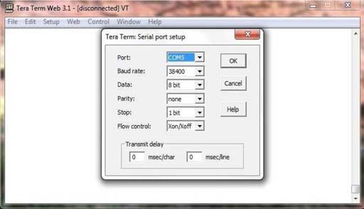
1.2 General Information
1.2.1     User Guide & MSI-3460 Conventions
    1. Keys used in operations are printed in BLUE and capitalized.
    2. Screen shots that are used in menus are displayed in RED and shown in a 7-
       segment font. Not all characters can be displayed with this font, but a close
       approximation is shown.
    3. If a function key does not work, it is probably because the MSI-3460 is not setup
       to support the key. For example, if the User key is set for TOTAL, you must also
       set up the TOTAL mode in the Setup Menu.
    4. When in Setup menus, the ZERO key drops back one menu level. At the root
       menu level, the ZERO key stores the changes and returns to the weight mode.
    5. When in Setup menus, the POWER key returns you directly to the weight
       display without storing the changes.
    6. When in Setup menus, the USER key functions as the scroll key.
    7. When in Setup menus, the TARE key functions as the ENTER/SELECT key.

4    MSI-3460 Operator’s Manual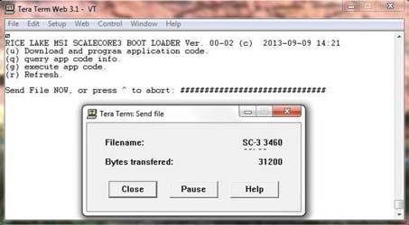
1.3 MSI3460 Annunciators
The MSI-3460 uses blue and red LEDs to indicate weight mode and other
information.
Blue LED - Indicates that the weight has not settled within the motion
MOTION window (usually ±1d).
While this symbol is illuminated, the scale will not zero, tare or totalize.
Center-of-Zero – Blue LED - Indicates the weight is within 1/4d of zero.
0
PEAK Blue LED - Indicates the scale is in peak hold mode.
Blue LED - Indicates the scale is in Net weight mode.
NET
A tare weight is subtracted from the gross weight.
Blue LED - Indicates the scale is in the Gross weight mode.
GROSS
All hook weight is displayed minus any zero offset.
Blue LED - Indicates the scale is displaying the Total weight.
TOTAL
This is a temporary display lasting less than five seconds.
Blue LED - Usually used in conjunction with the TOTAL LED allows
X1000
accumulation of weight beyond the five digit display capacity.
Appears when approximately 10% of battery life remains and blinks
LO BATT
when automatic shutdown is imminent.
kg Red LED - Indicates weight display is in kilograms.
lb Red LED - Indicates weight display is in pounds.
User programmable set points for early overload warnings.
SET POINTS Blue LED - Setpoint 1 and 2
Red LED - Setpoint 3
Acknowledge LEDs are used to provide feedback to the operator
Blue LED - Incoming remote commands have been received
ACK
Red LED - Light briefly once executed. Also used for acknowledging
successful Auto-Total operations.
Blue LED - Indicates carrier detect for RF remote display equipped
MSI-3460. If the LED is illuminated, MSI-3460 and remote display are
RF linked.
On units equipped with the RF remote control, the LED is illuminated
when a remote command is received and for the next half second.
Introduction 5
1.4 Specifications
Accuracy ±(0.1% +1d). ‘d’ equals one displayable increment.
Resolution Standard displayed resolution: 2500-3750’d’. Resolutions to
10000’d’ (non LFT units only) are possible. Internal A/D resolution
24 bits.
Standard lb 250 500 1000 2000 5000 10,000 15,000
Capacities kg 125 250 500 1000 2500 5000 7500
Power Battery operated, 6V rechargeable sealed lead acid battery pack
(standard Challenger Charger) Typically 50 hours of battery life with
automatic sleep mode and automatic power off.
Display Five digit, large 1.5 in (38 mm) numeric red GaAIAs Light Emitting
Diode (LED)
Operating Temp -40°F to +122°F (-40°C to +50°C), LFT range -10°C to +40°C
Operating Time 50 hours typical/100 hours max. (depends on operating mode)
Enclosure NEMA 4/IP65 powder coated alodined cast aluminum
Load Cell Standard 350 Ω Bridge, S-Beam
USER Programmable multifunction button for use as
TEST, TOTAL, UNIT, PEAK, NET/GROSS, VIEW TOTAL, LEARN
(for RF Remote Control), HI-RES
CAL Front panel calibration switch (located behind wire sealable screw)
Initiates full digital calibration procedure
Auto Zero Standard, can be disabled internally
Maintenance
Auto-Off Mode Prolongs battery life by turning POWER off after 15, 30, 45 or 60
minutes (operator determined) of no scale activity
Auto-Sleep Mode Prolongs battery life by dimming LED display after 5, 15, or 30
minutes of no activity
Units kg, lb (other units available with custom calibrations)
Filtering Selectable: OFF, Low (LO), Medium (HI-1), High (HI-2)
Totalization Standard: Press button or automatic; TOTAL weight up to 99999 X
1000 kg or lb
Peak Uses unfiltered faster reading of A/D, (>220 readings per second)
Setpoints Three internal standard setpoints and three ultra bright LEDs on
front panel
Service Counter Two independent 32 bit registers; register 1 updated each time
weight exceeds 25% of capacity; register 2 updated each time
weight exceeds overload; when register 1 exceeds 16383 or
register 2 exceeds 1023, display reads “Cnt” for load cell counter;
Test function shows the two readings in order
Construction All of these features are housed in a single, low-profile, cast
aluminum housing consisting of three sections:
The front of the scale houses the display, controls and all
electronics
The center section contains the load cell, lifting eye and hook
The rear of the scale features a quick access battery compartment
Table 1-1. Specifications
6 MSI-3460 Operator’s ManualOPTIONS
Wireless Remote 50 (15 m) typical range Light-of-Sight. Uses 418 MHz (USA)
Controler handheld transmitter.
802.15.4 RF Integral 802.15.4 RF Modem for connectivity to Optional MSI-8000
Modem for RF Remote Display.
connectivity with
MSI-8000 RF
Remote Display
MSI-8000 RF 100 (30 m) typical range line of sight. Uses 802.15.4, 2.4 GHz
Remote Display transciever
Table 1-1. Specifications
The MSI-3460 scale has a safe mechanical overload of 200%, and
WARNING an ultimate overload of 500%. Overloads greater than 500% may
result in structural failure and dropped loads. Dropped loads may
cause serious personal injury or death.
Introduction 71.5 Features
• Designed to meet or exceed all U.S. and international standards.
• Typically 50 hours of weighing time utilizing automatic sleep mode.
• Automatic power off conserves battery life by sensing no activity after 15, 30, 45
or 60 minutes, determined by operator, and turns off power.
• Automatic Sleep Mode preserves battery life by dimming the LED display after
5, 15, or 30 minutes of no activity.
• Rugged construction throughout. Buttons are sealed and rated for over one
million operations.
• Precise high resolution (2500 division standard and up to 10,000 possible) 24 bit
A/D conversion coupled with advanced RISC micro controller provides world
class features and accuracy.
• Five large, 1.5 inch (38 mm) LED digits for clear weight readings from a
distance.
• Easy to maintain: full digital calibration assures reliable, repeatable
measurements. Can be calibrated without test weights using MSI R-Cal
technology.
• Selectable for kg/lb unless prohibited by LFT regulations.
• Automatic or manual weight totalization for loading operations.
• Easily customized for special applications.
• Hi speed PEAK mode for wire and rope stress analysis.
• Three setpoints can be set for any in-range weight for operator alerts or process
control.
• ScaleCore technology provides quick and easy software updates and calibration/
setup backup.
• Two service counters ensure load train safety by warning the user to perform a
load train safety check when the lift count gets high or the scale has been
overloaded repeatedly.
1.6 Options
Options which you may have ordered with your Challenger 3 may include the
following:
• RF remote controller
• RF modem for connectivity to MSI-8000 RF Remote Display
• MSI-8000 RF Display
• 85-265 VAC input power.
• Audible alarm (triggered by setpoint 1)
1.7 Unpacking
When unpacking the scale from the shipping container, ensure that all assembly parts
are accounted for. Check the scale for any visible damage and immediately report any
damage to your shipper. It is advisable to use the original shipping container when
shipping or transporting the Challenger 3.
8 MSI-3460 Operator’s Manual1.8 Assembly
Battery
Load
Clevis
Hook Clevis Cotter
Figure 1-2. MSI-3460 Assembly
1. Slide hook clevis over load cell with open end of hook toward front of scale.
2. Align holes of clevis and load cell.
3. Slide the clevis pin through the clevis and load cell holes.
4. Lock clevis pin in place with cotter pin. Bend cotter pin.
Scale will be unsafe for use if clevis pin is not properly secured
WARNING with the cotter pin.
5. Slide battery pack into battery compartment. The battery will automatically
engage with its connectors.
6. Secure battery pack by turning the two locking fasteners on access door
clockwise 1/4 turn.
7. The scale is now ready for use.
Introduction 91.9 Battery Pack
The MSI-3460 is powered by a six volt rechargeable battery. The battery door is part
of the battery pack.
Access Door Fastener
Handle
Figure 1-3. Battery Pack Removal
To Remove the Battery Pack
1. Turn the two fasteners on the access door counter clockwise 1/4 turn,
2. Grasp handle and pull the battery pack straight out. The battery will
automatically disengage from its connectors.
The battery will operate for up to 100 hours (depending on LED brightness setting)
before requiring recharging. In order to conserve battery life, the scale includes an
automatic power off mode which senses operational status for no activity after 15, 30,
45, or 60 minutes, and turns the scale off. An additional battery saving feature is the
automatic sleep mode. This feature preserves battery life by dimming the display after
5, 15, or 30 minutes of no scale activity. Charging time for a completely discharged
battery is up to eight hours. A spare battery pack is recommended to keep the
Challenger 3 in continuous operation.
Note
To obtain maximum service life from your batteries they should be stored
between -4°F and 122°F (-20°C and +50°C). Stored batteries should be
recharged every three months. Battery is fully charged when the status
indicator is flashing.
10 MSI-3460 Operator’s Manual1.10 Battery Charger
1. Remove the battery from the scale.
2. Plug battery charger into an AC power receptacle. The input voltage is universal
from 115/230 VAC, 50/60 Hz. If the power input plug doesn’t match, contact
MSI for information on international plugs.
3. Slide the battery charger connector plate over the top of the battery until the
battery terminals mate with the charger connectors, as seen through the two
observation holes.
4. Approximately six to eight hours is required to recharge a fully discharged
battery. If a battery was deep discharged, more time might be required, but the
MSI-3460 prevents deep discharging. Partially discharged batteries will finish
the charge faster.
The charger is a three stage float charger that can be left on the battery indefinitely. It
has a dual color LED to indicate the charging state: RED- fast charge mode. GREEN-
charged or float charge.
Charger Connectors
Observation
holes
Inside of charger
Figure 1-4. Battery Charger
To obtain maximum service life from your batteries, the manufacturer
Note
suggests recharging after each 20 hours of use. Continuous deep
discharging will reduce maximum battery life cycle estimated at 2000
cycles.
A second battery is recommended to enable you to use your scale
continuously. Keep one on the charger while the other is in service.
Introduction 112.0 Operation
2.1 Power
To turn on the power.
1. Press POWER
, the following will display in order:
• LED will light all segments at full brightness as a display test.
• Display brightness will change to the setting determined in the display menu.
• Software version number will display.
• The MSI-3460 is ready for use.
2.2 Zero
Sets the zero reading of the Scale. Use the ZERO key to take out small deviations in
zero when the scale is unloaded. See “TARE” for zeroing (Taring) package or pallet
weights.
1. Press ZERO
The weight reading must be stable within the motion window for the zero
Note
function to work.
The scale digits display 0 (or 0.0 or 0.00, etc).
The backup memory in the MSI-3460 stores the zero reading, and can
restore it even if the power fails.
Rules for Use:
• Works in GROSS mode or NET mode. Zeroing while in net mode will zero
the gross weight causing the display to show the negative tare value.
• The scale must be stable within the motion window. The scale will not zero
if the motion detect annunciator is on. The scale will “remember” that it has
a zero request for two seconds. If motion clears in that time, the scale will
zero.
• The scale will accept a zero setting over the full range of the scale (NTEP
and other Legal for Trade models may have a limited zero range). Zero
settings above 4% of full scale will subtract from the overall capacity of the
scale. For example if you zero out 100 lb. on a 1000 lb. scale the overall
capacity of the scale will reduce to 900 lb. plus the allowed over-range
amount.
12 MSI-3460 Operator’s Manual2.3 Tare
Tare is typically used to zero out a known weight such as a packing container or pallet
and display the load in NET weight. A tare value is entered by pressing the TARE
key. The TARE function in the MSI-3460 is defined as a Tare-In, Tare-Out operation.
The first press of the TARE key stores the current weight as a tare value and then the
scale subtracts the tare value from the gross weight and changes the display to NET
mode. The next press of the TARE key will clear the tare value and revert the display
to GROSS mode.
To view the gross weight without clearing the tare value, program the USER key to
the function “NET/GROSS.” The RF remote control has a Net/Gross permanently
available.
To Tare and Display the Net Weight
1. Press
TARE
The weight reading must be stable within the motion window for the tare
Note
function to work.
The scale digits display 0 (or 0.0 or 0.00, etc) and the weight mode
changes to NET.
The backup memory in the MSI-3460 stores the tare reading and can
restore it even if power fails.
To Clear the Tare and revert to Gross Weight
1. Press . The net annunciator will turn off and the gross annunciator will
TARE
turn on.
Tare - Rules for Use:
• Only positive gross weight readings can be tared.
• The motion annunciator must be off. The weight reading must be stable.
• Setting or changing the tare has no effect on the Gross zero setting.
• Taring will reduce the apparent over range of the scale. For example, taring a
100 lb container on a 1000 lb scale, the scale will overload at a net weight of
900 lb (1000-100) plus any additional allowed overload (usually ~4% or 9d).
• The scale stores the tare value in non-volatile memory and is restored when
power is cycled.
Operation 133.0 User Defined Function Keys
The following function descriptions are for optional user defined functions that are
programmed on the front panel USER key or the two function keys (F1 & F2) on the
RF remote control. The functions TOTAL, VIEW TOTAL, and NET/GROSS are
available full time on the RF remote control. To enable any of the USER key
functions, you must set up the USER keys following the procedures in Section 4.0.
TEST
The TEST function provides an LED test that lights all LEDs at once, next the SW
Model number followed by the software version number, the battery voltage, and then
performs a display test that counts from 00000 to 99999. Other internal tests are
performed and if any test fails, an error code will display. See Section 8.0 for a
description of all error codes. Press the USER key again within two seconds to enable
a single step through all the test functions. In the single step mode, use the USER key
to scroll through the available test functions and the TARE key to start or display the
individual tests. Use the ZERO key to exit individual tests. Use the ZERO key to exit
entirely from the TEST function.
CH3.5n – Challenger 3 software version number: Press TARE to see the software
version.
bAtt – Battery voltage: Press TARE to see the battery voltage.
d.tESt – Display test: Press TARE to have the display count up from 00000 to 99999.
C-CAL – Cal constant display: Press TARE to view the C-CAL value.
TOTAL
Note
The total mode must be programmed from the setup menus before the
USER key will function.
For accumulation of multiple weighments. The accumulator always uses the
displayed weight, so GROSS and NET readings can be added into the same TOTAL.
There are four modes of totalizing: manual and three auto modes. The manual mode
requires the TOTAL button be pressed with the weight on the scale. The weight will
be added to the previously accumulated value. This assures that a weight on the scale
is only added to the total once. Both the manual and three auto total modes require
that the weight on the scale return below 0.5% (relative to full scale) of GROSS
ZERO or NET ZERO before the next weighment can be added. Applied weight must
be ≥1% of full scale above GROSS ZERO or NET ZERO before it can be totaled.
MANUAL TOTAL
The USER key under the MANUAL TOTAL mode functions in this manner:
Weight is > 1% of Capacity and has not been totaled – Pressing the USER key
will add the current weight to the TOTAL weight. The ACK LEDs blink to indicate
the weight was accepted. The TOTAL annunciator lights and the total weight is
displayed for five seconds and then the number of samples is displayed for two
seconds.
Current Weight has been totaled – Pressing the USER key will display the total
weight for five seconds (View Total) without changing the total value. The TOTAL
annunciator will light during the TOTAL weight display. After five seconds of total
weight display, the number of samples is displayed for two seconds.
Weight isAUTO TOTAL
The USER key under the AUTO TOTAL mode functions as Auto Total On / Auto
Total Off.
The auto mode has three variations which are programmed in the SETUP menu:
• AutoLoad – Any settled weight above the ‘Rise above’ threshold will be
automatically totaled. Then the scale must fall below the ‘Drop below’ threshold
before another total is allowed.
• AutoNorm – This mode takes the last settled weight to auto total with. The total
occurs only once the scale goes below the threshold. This allows the load to be
adjusted without a total occurring. Once the load is removed, the scale uses the
last settled reading for total.
• AutoHigh – Similar to the AutoNorm mode except the scale uses the highest
settled reading. Useful for loads that can’t be removed all at once.
View Total
The function key activates the total weight display followed by the number of
samples. While the display is showing the total, total is cleared by pressing ZERO.
Net / Gross
Switches the display between net and gross modes. Net weight is defined as gross
weight minus a tare weight.
To switch between net mode and gross mode:
1. Press the USER key (Setup to the Net/Gross function).
2. The NET/GROSS key will only function if a tare value has been established.
3. Switching back to gross mode from net mode will not clear the tare value. This
allows the operator to use the gross mode temporarily without having to re-
establish the tare value. Only clearing the tare or setting a new tare will change
the tare value held before switching into gross mode.
OIML LFT units only: The NET/GROSS key is temporary action only. The gross
weight is displayed for two seconds and then the display returns to the net mode. The
only way to return to permanent gross readings is to clear the tare (see clear tare
procedure).
PRINT
If print option is installed this menu choice will appear. The setup of the print function
is covered in the option manual.
LEARN
Used for programming the RF remote control. This function is detailed in Section 6.0.
PEAK HOLD
Peak hold will only update the display when a higher peak weight reading is
established. The peak hold function uses a high speed mode of the A/D converter
allowing it to capture transient weights at a far higher rate than typical scales. Peak
hold is cleared and re-enabled with the USER key.
PEAK HOLD is not available on NTEP or OIML certified Legal for Trade scales.
UNIT
The function key will switch the weight units between pounds and kilograms.
UNIT switching is not available on OIML certified Legal for Trade scales.
User Defined Function Keys 154.0 Configuration
4.1 Menu Map
USER KEY AUTO OFF TIME
FUNCTIONS 2II Disabled (default)
2))
Off 15 minutes
With the Power off, hold Test Display WHVW 30 minutes
down the USER key, then (default)
turn the Power on. *Total WRWDO 45 minutes
Or press POWER and USER
simultaneously
*View Total YWWO 1 hour
*Net/Gross 1(W U
F Remote Learn /HDUQ
SLEEP DELAY
USER **Units 3+OG
***Peak Hold 8QLW
2)) Off, Sleep disabled
5 Minutes (default)
POWER 15 Minutes
30 Minutes
SETUP MENU
LED DISPLAY INTENSITY
Function User Key 1 )YQF DYWR Auto by Light Sensor (default)
Function User Key 2
F2 is only on the RF Remote IYQF
/R Dim (longest battery life)
Auto Off Time DII
/R Medium Dim
+L Medium Bright
Sleep Mode 6/((3 +L Maximum Bright
Display Intensity GLVSO Number Entry
Set Point 1 6W3W 2)) Set Point Off (default)
F Set Point 2 6W3W UHDW Greater Than
USER
Set Point 3 6W3W
/(66 Less Than
TOTAL MODE
Total Mode WRWDO 2II Total Off (default)
**Weight Filter ILOWU WWO2Q Total On Manual
Totals by pressing the USER key
***Weight Units 81L7 kg lb $/R$' Autototal on Load
Totals on first stable load
* Function always available on the RF Remote
$/$6W Autototal Last
Totals the last stable load before zero return
** Function not available or non-functional in OIML R76 & 1Unit modes
*** Function not available or non-functional in OIML R76 or NTEP HB44 modes
$+L K Autototal on High Load
Totals the highest stable load
Autototal Last and Autototal High total when the scale is unloaded.
EXIT and Cancel Changes
POWER
EXIT and SAVE
SOFTWARE FILTER
ZERO
II OFF (disabled)
ENTER / SELECT /R Low (default)
TARE
F SCROLLs through +L High Filter
Menu Choices
USER +L Very High Filter
Figure 4-1. Setup Menu Map
16 MSI-3460 Operator’s Manual4.2 Function Keys
The MSI-3460 has one user definable function key on the front panel, and an
additional user definable function key on the RF remote control that can be
programmed to any of several functions.
Function Key Setup
1) With the 3460 off, press and hold Hold
the USER key, then press the
POWER key. F
...or while the 3460 is on, press USER USER POWER
and POWER simultaneously.
2) The first item of the Setup Menu
is Func1. F )YQF
USER
3) To set up the User key press
TARE . The current User key
function is displayed. 2IIblinking
7HVW
blinking
TARE
4) Select the User key function by
scrolling through the choices with
the USER key. See the list of
F WRWD/blinking
F YWWOblinking
available functions on the Setup USER USER
Menu Map.
This procedure scrolls through all
F QHW Ublinking
F /($U1blinking
USER USER
available choices for illustration
purposes only.
In this example, we’ll set F1 to the TEST
F 3KOGblinking
F XQLW
blinking
USER USER
function.
F 2II
blinking
F WHVW
blinking
USER USER
5) When the desired User Key
function is displayed, press
TARE . The next item in the Setup )YQF
Next Setup Menu Item
Menu appears. TARE
6) Either press ZERO to exit Setup
Cancel all setup
and store all changes, or
continue to another Setup Menu 6WRUH POWER
changes
item using the USER Key. ZERO Store and return to
weight display
Figure 4-2. Function Keys
Configuration 174.3 Auto- Off
The Auto-Off feature, when enabled, prolongs the battery life of the scale by turning
POWER off when the scale is not in use. Any time a button is depressed (any button),
or the detected weight is in motion exceeding 5 or 10d, the time limit is reset.
Therefore, the scale will stay on indefinitely if the weight is changing or any button is
pressed at least once. With Auto-Off disabled, the scale will remain on; only pressing
POWER will turn it off (or if the battery is depleted).
Auto-Off Setup
1) With the 3460 off, press and hold Hold
the USER key, then press the
POWER key. F
...or while the 3460 is on, press USER USER POWER
and POWER simultaneously.
2) The first item of the Setup Menu
is Func1. Scroll to “A-OFF” with F )YQF F $2))
the USER key. USER USER
3) To set up the A-Off timing, press
TARE. The current Auto-Off time 2IIblinking
is displayed. TARE
4) Select the Auto Off time by
scrolling through the choices with
F
blinking
F
blinking
USER USER
the USER key.
In this example, we’ll set 60 minutes as
the Auto-Off time.
F
blinking
F
blinking
USER USER
5) When the desired time is
displayed, press TARE . The next
item in the Setup Menu appears. GLVS/
Next Setup Menu Item
TARE
6) Either press ZERO to exit Setup Cancel all setup
and store all changes, or
continue to another Setup Menu
6WRUH POWER
changes
ZERO Store and return to
item using the USER key. weight display
Figure 4-3. Auto-Off
18 MSI-3460 Operator’s Manual4.4 Sleep
The SLEEP feature reduces power consumption by automatically turning off the
display during periods of inactivity. When in the sleep mode, the red acknowledge
annunciator blinks at a one second rate. To wake up either a button must be pushed
(front panel or RF remote), or the weight must change by 5d or more.
Note
SLEEP must be set to less time than the Auto-Off timer. For example, set
SLEEP to five minutes and Auto-Off to 30 minutes.
Sleep Setup
1) With the 3460 off, press and hold Hold
the USER key, then press the
POWER key. F
...or while the 3460 is on, press USER USER POWER
and POWER simultaneously.
2) The first item of the Setup Menu
is Func1. Scroll to Sleep with F )YQF F 6/((3
the USER key. USER USER
3) To set up the sleep timing, press
TARE. The current Auto-Off time 2IIblinking
is displayed. TARE
4) Select the sleep start time by
scrolling through the choices with
F
blinking
F
blinking
USER USER
the USER key.
In this example, we’ll set 30 minutes as
the sleep start time.
F
blinking
USER
5) When the desired time is
displayed, press TARE. The next
item in the Setup Menu appears.
6W3W
Next Setup Menu Item
TARE
6) Either press ZERO to exit setup
and store all changes, or
continue to another Setup Menu
6WRUH
ZERO Store and return to
item using the USER key. weight display
Figure 4-4. Sleep Setup
Configuration 194.5 Display Brightness
The display setup menu is used to set the display brightness. There are four fixed
brightness settings, and one automatic light sensing brightness setting. The auto
setting will automatically detect the ambient light and adjust the brightness of the
display accordingly. Bright light will cause the display to be at the brightest setting.
The display brightness will reduce as ambient light reduces. The four fixed brightness
settings, LO-1, LO-2, HI-1, and HI-2 change the average current in the display.
Lower settings increase battery life.
Display Brightness Setup
1) With the 3460 off, press and hold Hold
the USER key, then press the
POWER key. F
...or while the 3460 is on, press USER USER POWER
and POWER simultaneously.
2) The first item of the Setup Menu
is Func1. Scroll to diSPL with F )YQF F GLVS/
the USER key. USER USER
3) To set up the display brightness,
press TARE. The current
brightness setting is displayed.
/R
dimmest setting
F /R
medium low setting
TARE USER
4) Select the display brightness by
scrolling through the choices with
the USER key. The menu
F +L
medium high setting
F +L
brightest setting
USER USER
brightness changes as you scroll
through the choices.
In this example, we’ll set the brightness
F $YWR
light sensing auto setting
USER
to the AUTO, light sensing brightness
control.
5) When the desired display
brightness setting is displayed,
pressTARE. The next item in 6/((3
Next Setup Menu Item
the Setup Menu appears. TARE
6) Either press ZERO to exit Setup Cancel all setup
and store all changes, or
continue to another Setup Menu 6WRUH POWER
changes
item using the USER key. ZERO Store and return to
weight display
Figure 4-5. Display Brightness
20 MSI-3460 Operator’s Manual4.6 Set Points
The MSI-3460 supports three setpoints. Common uses of setpoints are for warnings or
process control. The MSI-3460 comes standard with LED outputs for a triggered set
point. Setpoint 1 and 2 are Blue LEDs and Setpoint 3 is Red. The MSI-3460 has an
audible output option that is triggered by Setpoint 1. Contact MSI for other setpoint
output options.
Setpoint Setup
1) With the 3460 Off, press and Hold
hold the USER key, then press
the POWER key. F
...or while the 3460 is on, press USER USER POWER
and POWER simultaneously.
2) Scroll through the setup menu
choices by pressing the USER F VWSW
key. Stop when the LED displays USER
StPt1, StPt2, or StPt3.
3) When the desired setpoint is
displayed, press TARE. The 2II
blinking
display blinks OFF, or if TARE
previously programmed, the last
set mode.
4) Select the setpoint mode by
F
USER
UHDW
scrolling through the choices with
theUSER key. GrEAt (greater
than) indicates the setpoint will
trigger when the weight exceeds
F /(66
USER
the value. LESS (less than) will
trigger the setpoint when the
weight is less than the value. This
F UHDW
example scrolled through all available USER
choices for illustration purposes only.
5) When the desired setpoint
mode is displayed, press TARE blinking
URV6
TARE Set Point responds to Gross Weight regardless of the display.
6) Next select the type of weight
value the setpoint is assigned
to. Use the USER key to scroll
F QHW U
blinking
USER
through the choices. Set Point responds to Net or Gross Weight.
This example scrolled through all
available choices for illustration
purposes only. In this example, we’ll
F WRWDO
blinking
USER
enter gross as a weight mode because Set Point responds to the Totaled Weight.
we are going to use the setpoint as a
safety warning. F WFQW
blinking
USER Set Point responds to the Total Count (number of samples).
7) When the desired weight mode
is shown, push TARE. Next the
F URV6
blinking
USER
current setpoint value is Set Point responds to Gross Weight regardless of the display.
displayed. If there was a previous
value, it is displayed. If no value has
been entered, a zero will appear. To blinking
keep the displayed value, press ZERO TARE
Figure 4-6. Set Point Setup
Configuration 218) Press the USER key. The first
digit blinks at zero. Use the
F
blinking
USER
USER key to scroll through the
numbers. When the desired
number is shown, push TARE.
F
blinking
F
blinking
USER USER
In this example, we’ll enter 240 as a
setpoint value.
To enter a decimal point, push
fixed
F
blinking
POWER while the digit is blinking. TARE USER
Error Correction: If you input a
wrong value, press ZERO to step
back one digit and change the digit
F
blinking
F
blinking
USER USER
with the USER key.
F
blinking
F
blinking
USER USER
9) When the desired number is
shown, push TARE a second
time to set the value. The next
fixed
F blinking
TARE USER
setup menu item is displayed.
10)Either press ZERO to exit setup
fixed
6W3W
next setup menu item
and store all changes, or TARE TARE
continue to another setup menu
item using the USER key. 6WRUH Cancel all setup
changes
ZERO Store and return to
weight display POWER
Figure 4-7. Set Point Setup Continued
22 MSI-3460 Operator’s Manual4.7 Total Mode
The MSI-3460 can keep track of all weighments using the total feature. Either manual
total, which totals by pushing a configured USER key on the front panel or the RF
remote, or auto-total, which can be used to automatically add up each weighment. See
the total mode descriptions for details on the various total modes. To use manual total,
you must also program a user key. Auto total modes do not need a user key, but if a
user key is setup for total, then it will function as a total on / total off.
Total Mode Setup
1) With the 3460 off, press and hold Hold
the USER key, then press the
POWERkey. F
...or while the 3460 is on, press USER USER POWER
and POWER simultaneously.
2) The first item of the Setup Menu
is Func1. Scroll to totaL with F )YQF F WRWD/
theUSER key. USER USER
3) To setup the Total Mode, press
TARE. The current Total Mode
setting is displayed.
2))
blinking, Total Off
F WWO2Q
Total with pushbutton
TARE USER
4) Select the Total Mode by scrolling
through the choices with the
USER key.
F $/RDG
Total on stable load
F $/$67
Total last stable load
In this example, we’ll set the Total Mode USER USER
to the Auto-High mode. The Auto High
mode uses the highest stable reading
as the total value, and totals when the
load is removed.
F
USER
$+L +
Total highest stable Load
5) When the desired Total Mode
setting is displayed, press TARE.
The next item in the Setup Menu )LOWU
Next Setup Menu Item
appears. TARE
6) Either press ZERO to exit Setup
and store all changes, or
continue to another Setup Menu
ZERO
6WRUH Cancel all setup
changes
item using the USER Key. Store and return to POWER
weight display
Configuration 234.8 Units
Units can be changed in two ways:
• Program a user function key to units
• Change the units with the setup menu with the following procedure
Note OIML LFT scales do not allow units to be changed.
Units Setup
1) With the 3460 off, press and hold Hold
the USER key, then press the
POWER key. F
...or while the 3460 is on, press USER USER POWER
and POWER simultaneously.
Func 1 Unit
2) The first item of the setup menu F
is Func1. Scroll to Unit with F
the USER key. USER USER
3) To setup the weight units, press
TARE. The display will blink UnitBlinking
Unit. TARE
4) Change the weight units by
pressing the USER key. The unit F kg lb
is indicated by the annunciators. USER
5) When the desired unit setting is
annunciated, press TARE. The
next item in the setup Menu
Func 1
Next Setup Menu Item
TARE
appears.
6) Either press ZERO to exit setup Cancel all setup
and store all changes, or
continue to another setup menu ZERO
StorE changes
Store and return to POWER
item using the USER Key. weight display
Figure 4-8. Units Setup
24 MSI-3460 Operator’s Manual4.9 Filter Setup
Changing the filter settings allows the scale to adjust to situations where there is a lot a
movement in the structure. If the reading is not stable, it can often be improved by
increasing the filter setting. Settling time will be longer as the filter setting is increased.
However, the MSI-3460 employs algorithms that speed up large weight changes while
still controlling vibration even with high filter settings.
Filter Setup
1) With the 3460 off, press and hold Hold
the USER key, then press the
POWER key. F
...or while the 3460 is on, press USER USER POWER
and POWER simultaneously.
2) The first item of the Setup Menu
is Func1. Scroll to Filtr with F )YQF F )LOWU
the USER key. USER USER
3) To setup the filter, press TARE .
The display will blink the current
filter setting.
2))
Blinking
TARE
4) Change the filter setting by
pressing the USER key. F 2))
Blinking
F /2
Low Filter, Blinking
USER USER
There are four available filter settings.
Not all choices are shown in this
example. F +L
High Filter 1
USER
5) When the desired filter setting is
displayed, press TARE. The
next item in the setup menu
appears.
8QLW
Next Setup Menu Item
TARE
6) Either press ZERO to exit setup
Cancel all setup
and store all changes, or Store and return to changes
continue to another setup menu weight display
ZERO POWER
item using the USER key.
Figure 4-9. Filter Setup Menu Map
Configuration 255.0 Calibration
The MSI-3460 is calibrated using standard weights. It is required that the weight used
is at least 10% of full capacity in order to achieve rated accuracy. For example, use at
least a 500 kg test weight to calibrate a 5000 kg capacity scale. Although a single span
point is usually adequate for rated accuracy, the MSI-3460 supports Multi-Point
calibration with up to 4 span points + Zero.
When adequate test weights are not available, the MSI-3460 can be calibrated using a
calculated constant calibration which is referred to as C-Cal. To use C-Cal, a
previously generated C-Cal number must be known. MSI supplies replacement load
cells for the MSI-3460 with the C-Cal value stamped on the serial number label.
There are three types of calibration:
• Standard Calibration – is used for maintenance and routine calibration.
• Initial Calibration – is used to set up both the capacity and resolution (d) of the
scale. It differs from standard calibration only in the initial steps. Initial
calibration is performed after a calibration reset which completely erases the
calibration and setup memory.
• C-Cal – If the last calculated C-Cal values is known, the scale can be calibrated
without weights.
Standard Calibration Procedure
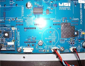
1) Remove the seal screw. With Cal Switch
a small screwdriver press the Press Switch
LO BA Remove CAL behind the hole
Cal Switch behind the seal with a small
Hex Seal
screw. Screw Screwdriver
CAL
The CAL Setup Menu
appears.
&$/
2) Press TARE to Start the
Calibration Procedure.
TARE
3) The display reads UnLd
(unload) indicating you
should remove all weight XQ/G No weight
on hook
from the hook.
4) Ensure the 3460 is
motionless, then press
TARE . The 3460 sets the
zero calibration point. Wait
blinking
Flashes
Zero
TARE
while the display is blinking.
5) If the zero is in range, the
scale will display PASS.
Then LoAd1 is displayed.
3$66
6) Load the scale with a
precision test weight. For single
span point calibrations a test weight /R$' Lift Test
Weight
of 20% of capacity or more is
recommended.
7) Press TARE . The 3460
flashes the capacity. If you
are loading the scale with
example capacity
Blinks
Capacity
the capacity weight, skip to TARE
step 10.
Figure 5-1. Standard Calibration Procedure
26 MSI-3460 Operator’s Manual8) To enter a calibration
weight other than
capacity, press USER. The
F
blinking
display far left digit will USER
flash zero indicating that Error Correction: If you input a wrong
a number should be value, press ZERO to step back one
entered. digit and reenter.
9) Press the USER key to
scroll the number and
the TARE key to enter
F
blinking
F
blinking
USER USER
each digit of the
calibration weight.
In this example, we’ll enter 2500
kg on a 5000 kg capacity scale.
fixed
F blinking
TARE USER
Do not push the TARE key two
times in a row until the entire
number is showing.
To add a decimal point, push the
F
USER
5 times blinking
TARE
POWER key while the number is
blinking.
10) When the entire value of
the test weight is displayed TARE
fixed
F
USER
blinking
and the weight and scale
are stable, press TARE to
finish off the weight entry. TARE
fixed
F
USER
blinking
If the resultant cal value is
within limits, the display will
read PASS briefly. fixed
3DVV
TARE TARE
11) The display now reads
Load2. The 3460 To set Next
allows multipoint
calibration. If more cal
/RDG Span Point
TARE
points are desired (up to
3 additional) press To skip additional
Span Points
TARE. If a single point
cal is all that’s needed, ZERO
press ZERO and jump to
step 15.
12) Load the scale with the next
test weight. The display You can cancel calibration by
offers the reading that will
occur without adjusting the
pressing Power and the scale
will reset to the previous
calibration constants.
value. If the weight value Example Value only.
shown is acceptable push
TARE and skip to step 14.
If the calibrated value needs
adjusting, go to step 13.
Test weights can be any in-capacity
weight, the order is not important.
The 3460 supports 5-Point Cal, Zero
and up to 4 span points.
To Enter the digit
13) Press the USER key to To scroll the digit F into the cal weight
scroll the number and value
USER TARE
the TARE key to enter
each digit of the
calibration weight value.
When the entire calibration
To complete the cal
weigh value entry 3DVV
TARE
weight is displayed, push
TARE a second time to
finalize the calibration span
point. If the resultant cal
value is within limits, the
display will read “PASS”
briefly.
Figure 5-2. Standard Calibration Procedure, Continued.
Calibration 2714) The display now reads
LoAd3 or LoAd4.
Repeat steps 12 and 13
/RDG To enter another
for additional span points or span point
press TARE or press
ZERO if you are finished. /RDG TARE
After LoAD4 has passed, the 3460
will automatically advance to the next
step.
15) The display shows CAL’d
to indicate that the &$/G
calibration was successful.
16) Press TARE. The display
flashes C-CAL followed
by the C-CAL number. &&D/
Flashing
Make a note of this number. TARE Example Value only.
If the X1000 annunciator is lit,
also make a note of that.
This number is used to calibrate when To skip the C-CAL step
test weights are unavailable. C-CAL
does not replicate multipoint ZERO
calibrations.
17) Press ZERO to store the
calibration constants, or
after eight seconds, the
calibration constants will
VWRUH
ZERO
automatically stored. After
the store message is
displayed, the scale goes
to the next item on the cal
6HWYS CAL
LO BATT
menu, SEtuP.
18) Press ZERO to exit the Cal
menus and start up the
standard weight display. X1000
The 3460 is ready for use. ZERO
19) After ensuring the
calibration is acceptable,
replace the hex seal screw.
If the scale is being used as a Legal-
for-Trade device, place a lead-wire
seal through the cal screw over to
the adjacent screw.
Model No.
MSI-3460
Figure 5-3. Standard Calibration Procedure, Continued.
28 MSI-3460 Operator’s Manual5.1 Initial Calibration
Use this procedure only if the capacity and count by (d) needs to be modified. The
initial steps of the initial calibration will totally erase user setups as well as any
previous calibration.
Initial Calibration
Resetting Capacity and Countby (d)
1) Turn the 3460 off. Cal Switch
2) Remove the seal screw. With Press Switch
LO BA Remove CAL behind the hole
a small screwdriver press and Hex Seal
hold the CAL switch behind with a small
CAL Screw Screwdriver
the seal screw.
3) Still holding down the CAL
switch, press the POWER
switch.
4) The display blinks rESEt. UHVHW blinking
5) To reset all calibration
constants and setup
parameters, press TARE. TARE
6) The 3460 requests a
confirmation by displaying
Sure?. To cancel the Reset press
6YUH"
the POWER key.
7) To complete the reset, press
TARE. The Calibrate menu
appears. You must now TARE
&$/
recalibrate the system.
8) PressTARE to start the initial
calibration procedure. The
display shows Unit. You
8QLW
TARE
select the units you wish to
calibrate in.
9) Press TARE to select the
calibration unit.
8QLW blinking
TARE
10) Select the USER key to choose
between lb and kg. When the F kg lb
desired unit is shown, press USER
TARE.
11) Next, set the capacity in the
selected units. Capacity must
be set no higher than the load TARE
&$3
cell rated capacity.
12) Press TARE to enter the
capacity setting screen. A blinking
capacity of 10000 is the initial TARE Error Correction: If you input a
value.If 10000 units is the desired wrong value, press ZERO to step
capacity press TARE and skip to
back one digit and reenter.
step 16.
13) To change the capacity, press
USER.
F
blinking
To enter a decimal point, push
POWER while the digit is blinking.
USER
Figure 5-4. Initial Calibration
Calibration 2914) The first digit blinks. Use the
USER key to scroll through
the numbers. When the
desired number is shown,
push TARE.
F
blinking
F
blinking
USER USER
In this example, we’ll enter
2500 as a capacity.
fixed
F blinking
TARE USER
Continue inputing the desired
capacity using the USER key
for scrolling the number and
the TARE key to store the
F
USER
5 times blinking
TARE
number.
15) Finalize the capacity value fixed
F blinking
by pressing the TARE key on TARE USER
an unblinking display. In our
example, once the number
2500 is fixed on the display, TARE
fixed
F
USER
blinking
press TARE to store the
capacity value.
fixed
Capacity is set.
16) Next the scale division size TARE TARE
‘d’ is set. Press TARE to
begin. In this example we’ll set
the ‘d’ to 2 units. G
17) Select the USER key to TARE
scroll through the
recommended scale
divisions. The first ‘d’ offered is
the standard division for the given
capacity. Setting a ‘d’ size that
results in total resolution higher than
F blinking
F blinking
USER USER
1:5000 is not recommended for
stability reasons.
18) When the desired scale ‘d’
is displayed, press TARE .
The UnLd display
appears and the scale is
ready for calibration.
‘d’ is set. XQ/G Proceed to Standard
Calibration starting at Step 3.
TARE
Follow the standard
calibration procedure
starting at step 3.
Figure 5-5. Initial Calibration, Continued
5.2 Guidelines for Capacity and Resolution
Crane scales are subject to forces that regular floor scales do not see. Many bridge
cranes, hoist cranes, and mobile cranes lack rigidity and tend to bounce or swing
when loads are lifted. For this reason, MSI recommends that resolution is kept in the
1:2000 to 1:3000 range. Some improvement in stability can be achieved by increasing
the filtering. However, you should never program resolution that is far greater than
you need. If the MSI-3460 display is never stable, it is recommended that the
resolution is reduced and/or filtering increased.
30 MSI-3460 Operator’s ManualDue to LFT requirements and general scale design criteria, the weight must be stable
for certain features to work: ZERO – weight must be stable to be zeroed. TARE –
weight must be stable to be tared. TOTAL – weight must be stable to be added to the
total registers. One way to improve the stability is to increase the filtering, at the risk
of increasing settling time. The other is to increase the ‘d’ (reduce resolution). The
third way is to increase the motion window. The MSI-3460 defaults to ±1d as a
motion window. It can be changed at MSI to a higher value if desired. Often ±3d is
chosen for bridge cranes as these tend to have a lot of bounce to them. This of course
carries an accuracy penalty adding ±3 d to the total accuracy of the scale if the zero or
tare operation happens to capture the weight in a valley or peak.
Setting capacity is dictated primarily by the capability of the load cell. MSI supplies
the MSI-3460 in many capacities.
Never set the capacity of the scale higher than the rating of the load cell.
Due to excellent linearity of the MSI S-beam load cell, it is acceptable to set lower
capacities to better match the crane the MSI-3460 is used on. For example, if the hoist
is rated for 9000 lb. you can use an MSI 10000 lb. MSI 3460 and reset the capacity to
9000 lb. so that the scale will indicate overload at 9000 lb. instead of 10000 lb.
Derating as much as 50% of the capacity is usually acceptable, but the scale may be
less stable if the ‘d’ is decreased.
The capacity of all MSI-3460 systems is rated approximately 20% higher than the
rated capacity in pounds. This is to allow the kg capacity to be exactly 1/2 the number
of the pounds capacity.
5.3 C-Cal Calibration
When adequate test weights are not available, the MSI-3460 can be calibrated using a
programmed constant calibration which is referred to as C-Cal. To use C-Cal, a C-Cal
number must be known from a previous calibration. MSI supplies replacement load
cells for the MSI-3460 with the C-Cal value stamped on the serial number label.
When a calibration is performed with test weights, a new C-Cal is generated. C-Cal
can be used when the electronics are replaced to get an approximate calibration that
may be suitable for non Legal-for-Trade applications.
The C-Cal number must be known prior to starting this
Important procedure. For a MSI-3460 with its original load cell, MSI prints
this number on the calibration record, the serial number tag, and
on the calibration log found inside the battery compartment.
C-Calibration reduces slightly the absolute accuracy of the system if the electronics
are replaced or a new load cell is installed, and is intended for non-critical use only.
Legal-for-Trade installations require that the MSI-3460 is calibrated using test
weights. If a system was originally multi-point calibrated, the C-CAL calibration will
erase the additional span points, as C-Cal is only a two point calibration (Zero and
Span at 10% of capacity).
Calibration 31You can also read