Summertime Overheating Risk Assessment of a Flexible Plug-In Modular Unit in Luxembourg
←
→
Page content transcription
If your browser does not render page correctly, please read the page content below
sustainability

Article
Summertime Overheating Risk Assessment of
a Flexible Plug-In Modular Unit in Luxembourg
Michaël Rakotonjanahary 1, * , Frank Scholzen 1          and Daniele Waldmann 2
 1    Faculty of Science, Technology, and Medicine, Campus Kirchberg, University of Luxembourg,
      1359 Luxembourg, Luxembourg; frank.scholzen@uni.lu
 2    Faculty of Science, Technology, and Medicine, Campus Belval, University of Luxembourg,
      4365 Esch-sur-Alzette, Luxembourg; daniele.waldmann@uni.lu
 *    Correspondence: michael.rakotonjanahary@uni.lu

 Received: 31 August 2020; Accepted: 2 October 2020; Published: 14 October 2020

 Abstract: Modular buildings offer faster construction process, provide better construction quality,
 allow reducing construction waste and are potentially flexible. Frames of modular units can be
 made of metal, timber, concrete or mixed materials but lightweight structures do not always allow
 erecting high-rise buildings and generally present a higher risk of overheating and/or overcooling.
 To reconcile these pros and cons, a typology of modular building called Slab was designed by a group
 of architects. The building is composed on the one hand of a permanent concrete structure named
 shelf-structure and on the other hand of several flexible removable timber modular units, also known
 as modules. The shelf-structure will host the common utility rooms and will serve as docking
 infrastructure for the housing modules. To provide high flexibility, the Slab building was designed
 to adapt to any orientation and location in Luxembourg. An energy concept and a HVAC systems
 design has been developed for the Slab building. Furthermore, a two-fold sustainability analysis was
 carried out. The first part of the analysis regards the determination of the minimum required wall
 thicknesses of the modules in accordance with Luxembourgish regulatory requirements, although the
 current regulation does not yet consider the Slab building typology. The second part, which is
 the subject of this paper, is thermal comfort assessment, more precisely, summertime overheating
 risk assessment of these modules, in compliance with Luxembourgish standard. In this regard,
 dynamic thermal simulations have been realized on two module variants; the first fulfills the passive
 house requirements, and the second—the current requirements for building permit application,
 which in principle corresponds to low energy house requirements. Simulations showed that with
 adequate solar shading and reinforced natural ventilation by window opening, overheating risk
 could be avoided for the normal residential use scenario for both module variants.

 Keywords: plug-in architecture; modular building; flexible container unit; off-site construction;
 energy performance; dynamic thermal simulation; summertime overheating assessment

1. Introduction
     From 1850–1900 to 2006–2015, the mean land surface air temperature increased by 1.53 ◦ C,
while the global mean surface (land and ocean) temperature increased by 0.87 ◦ C [1]. According to
scenarios developed by different organizations, global warming would get worse if no drastic measures
are taken. The worst-case scenario Oceans developed by Shell company jointly with Massachusetts
Institute of Technology, for instance, foresees a global average temperature rise of more than 2.5 ◦ C
from 1861–1880 to 2100 [2]. Another worst-case scenario proposed by the French National Centre
for Scientific Research (CNRS) jointly with the French Alternative Energies and Atomic Energy
Commission (CEA) and Météo-France forecasts an increase of the global average temperature of

Sustainability 2020, 12, 8474; doi:10.3390/su12208474                     www.mdpi.com/journal/sustainability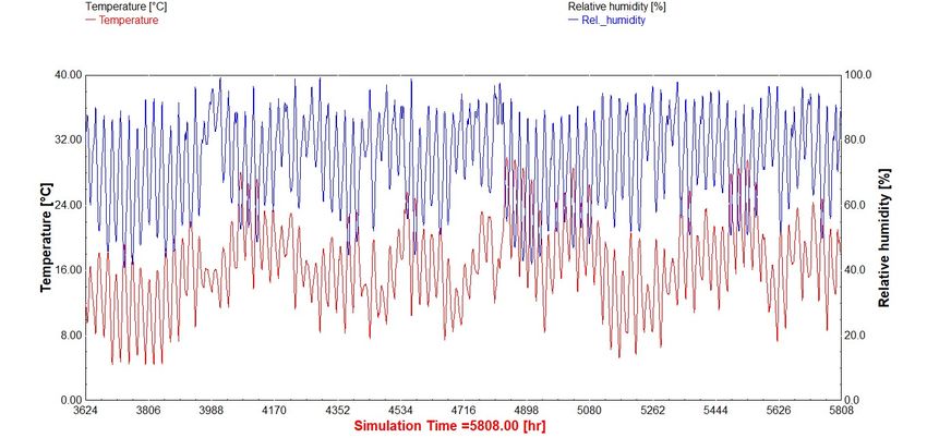
Sustainability 2020, 12, 8474                                                                      2 of 20

6 ◦ C up to 7 ◦ C in 2100 [3]. To face the challenges of climate change, the European Union adopted
in 2007 ambitious objectives for 2020. These were the reduction of greenhouse gas emissions by
20%, the increase of the share of renewable energy to 20% and the improvement by 20% in energy
efficiency [4]. Buildings consume more than 40% of global energy and are responsible for one third
of global greenhouse gas emissions [5]. Moreover, the lifecycle approach reveals that over 80% of
greenhouse gas emissions take place during the operational phase of buildings (for heating, cooling,
ventilation, lighting, appliances, and other applications) [5]. In this context, regulations regarding
energy performance of buildings are subsequently more demanding. In the European Union, the Energy
Performance of Buildings Directive (EPBD) 2010/31/EU [6], amended by the Directive 2018/844/EU [7],
requires all new buildings to be nearly zero-energy buildings (NZEB) by the end of 2020. In this respect,
building envelopes need to be well thermally insulated and designed in such a way as to take the
most advantage of solar gains, without, as far as possible, exposing buildings to overheating risk.
Moreover, buildings shall be constructed with eco-friendly materials and their heating, ventilation and
air-conditioning (HVAC) systems shall be efficiently designed while using renewable energy sources
as much as possible. Buildings shall ensure a minimum comfort to the tenants but on top of that,
they could be expandable/shrinkable to be capable of adapting to the increase/decrease of the housing
demand and be flexible so that they can fit any orientation and location. To combine all these criteria,
modular constructions could be a solution.
      A modular construction is an assembly of standardized-dimension building elements such as wall
panel, slab, beam or also an assembly of container-type units called “modules,” or else “prefabricated
prefinished volumetric construction (PPVC)” which are prefabricated in factory and afterwards
transported and assembled on-site. The naming of “container house” is given to transportable
modules that are completely finished in the factory and ready to be inhabited; for smaller units,
eventually with different shapes, the nomenclature of “living pod” or “capsule” is also found in
literature. Modular buildings are always prefabricated buildings, but the reverse is not necessarily
true. The degree of prefabrication and assembly technique mainly varies depending on the life span of
the building (temporary or permanent), the desired space layout and the technical equipment to install
(heating, electricity, sewer, plumbing, etc.). Compared to conventional constructions, modular buildings
have remarkable advantages. Firstly, they offer a faster construction process [8–10] and provide an
improved construction quality [10–13]. Secondly, they allow reducing construction waste [10,14,15],
construction interruptions and nuisances generated on-site [10]. Lastly, they offer a great flexibility
insofar as the modules can be refitted, relocated and refurbished. Frames of modules can be made of
metal, timber [14], concrete [15] or mixed materials but lightweight structure do not always allow to
erect high-rise buildings and generally present a higher risk of overheating and/or overcooling [16,17].
On the subject, Yoo et al. [18] carried out an interview on 23 residents of shipping container houses
in Seoul and Gyeonggi-do (Korea). The survey indicated that 14 out of 23 were dissatisfied with the
insulation of their housing. Regarding the environmental dimension, Aye et al. [19] conducted a study
on a prefabricated case study building. It was found that the modular timber construction presents
approximately the same embodied energy as the prefabricated concrete construction (10.49 GJ/m2
and 9.64 GJ/m2 of floor area, respectively), which is around 1.4 times less than that of the modular
steel construction (14.40 GJ/m2 ). The study also revealed that the total mass of the modular timber
construction (0.25 t/m2 ) is 4 times less than that of the modular concrete construction (1 t/m2 ) and
this aspect is very important for a construction to be portable or relocatable. Considering these pros
and cons, a typology of modular building called Slab, as presented in Section 3, was designed by a
group of architects and engineers within the team of the ECON4SD (Eco-Construction for Sustainable
Development) research project. The core objective of the ECON4SD project is to develop new building
components and design models to achieve maximum efficiency in terms of resource and energy
use. The two architects of the ECON4SD project, M. Ferreira Silva and F. Hertweck, have furthermore
developed two other building typologies, namely the Tower and the Demountable buildings; their
Sustainability 2020, 12, 8474                                                                     3 of 20

paper [20] provides more details on the design motivation and on the architectural aspect of these three
building typologies.
     The Slab building is a hybrid modular construction based on the plug-in concept or on Metabolism,
from a wider perspective. The plug-in concept was imagined by Le Corbusier around the 1950s when
he designed the Unité d’habitation (Cité Radieuse) [21] although it has never been realized in any
of his buildings. The plug-in concept involves a primary structure, in which prefabricated housing
units are slotted, whereas Metabolism [22] is a Japanese architectural movement established in the
late 1950s, combining megastructures with the principles of biological growth, in order to allow
buildings to expand/shrink. As a result, the Slab building is composed of a permanent reinforced
concrete structure named shelf-structure, and several flexible removable timber modules used as
housing units, as presented in Section 3. A two-fold study was carried out on the Slab building.
The first part of the study is the development of an energy concept and a HVAC system design for
the whole building. The second part involves a sustainability analysis on the modules, focusing on
energy aspect and on thermal comfort. The sustainability analysis was realized in accordance with
Luxembourgish regulatory requirements although the current regulation does not yet consider the Slab
building typology. The energy analysis regards the determination of the wall thickness of a module,
whereupon two module variants have been dimensioned. The first variant fulfills the requirements
for AAA energy class, which correspond to the passive house requirements in Luxembourg and
which is requisite to have a NZEB. The other one fulfills the current requirements for building permit
application, which in principle corresponds to the low energy house requirements in Luxembourg.
Since the two module variants have a relatively low thermal inertia as described in Section 4.2.1,
thermal comfort is a sore spot, which deserves particular attention. Thus, this paper aims at assessing
thermal comfort of the two module variants, more precisely, summertime overheating risk, which is
also a key step allowing to check the necessity of an active cooling system. To appraise the impact of
thermal mass on overheating, a fictive module version fulfilling the AAA energy class requirements
but presenting a higher thermal inertia was studied.

2. Literature Review
      Articles regarding thermal comfort assessment of modular constructions are scarce in literature.
Fifield et al. [17] conducted a summertime overheating assessment of thermally lightweight,
well-insulated, naturally ventilated modular healthcare buildings in the UK, according to British
standards. Depending on the usage of the rooms, British standards propose two methods to assess
overheating risk; these are modelling and in-use monitoring. The method used in their study was
in-use monitoring, predicated on both static and adaptive overheating criteria. Static overheating
criteria are only based on indoor environmental factors, more specifically on indoor temperatures
(e.g., dry-resultant temperature, operative temperature, air temperature) in contrast with adaptive
criteria, which additionally consider personal factors. The most popular thermal comfort assessment
based on adaptive criteria is the American Society of Heating, Refrigerating and Air-Conditioning
Engineers (ASHRAE) method. It proposes the predicted mean vote (PMV) model, under which the
highest comfort temperature in winter and summer are 24.3 ◦ C and 26.7 ◦ C (new effective temperature),
respectively [23]. Fifield et al. concluded that these modular buildings are at risk of summertime
overheating in a relatively cool UK summer condition.
      Regarding plug-in or flexible modular units, no studies on thermal comfort assessment have
been found in literature; nonetheless, few ones about thermal analysis, which are closely related to
thermal comfort assessment, have been listed. Ulloa et al. [24] realized a study on standard 20-foot
equivalent unit (TEU) shipping containers made of COR-TEN®steel, reused as service modules
(first aid module, shower module and refrigeration module) in the area of humanitarian help or
social emergency. The purpose of the study was to estimate the peak for the heating and cooling
demands in order to choose the adequate HVAC system for the modules. Modules were studied
in five locations spread in different climate areas according to the Köppen–Geiger classification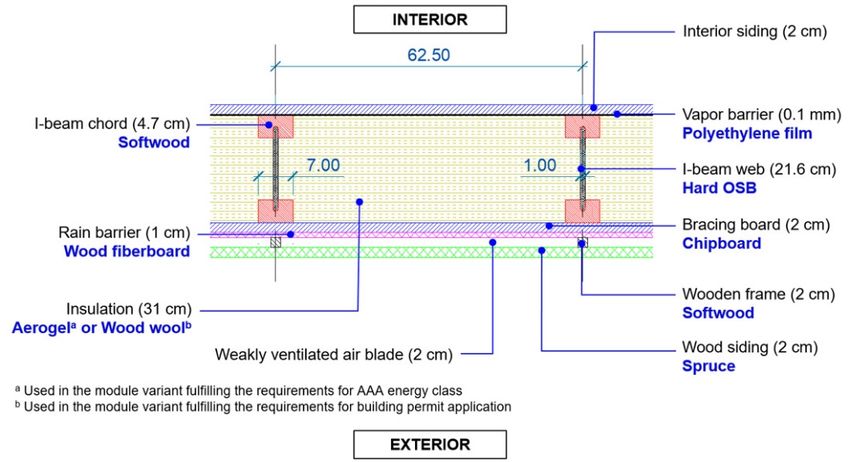
Sustainability 2020, 12, 8474                                                                      4 of 20

(equatorial, arid, warm temperate, snow and polar climates) [25], whereas their orientation was
fixed (window facing west). The thermal analysis involved dynamic thermal simulations (DTS) in
TRNSYS software (v.17, Thermal Energy System Specialists, LLC, Madison, WI, USA) whereby modules
geometry was modelled on Trimble SketchUp. The heating and cooling demands of the first aid module
were predicated upon EN ISO 13790 [26] from the temperatures range which allows maintaining
thermal comfort for a hospital that is from 22 ◦ C to 26 ◦ C. Kosir et al. [27] conducted a study to
evaluate energy and visual (daylight) efficiency of a flexible prefabricated modular unit of 6.5 m
length, 3.0 m width and 3.4 m height. The module was studied at five different locations (Reykjavik,
Hamburg, Munich, Athens and Abu Dhabi) while varying different parameters, namely the orientation,
the window-to-wall ratio (WWR), the window distribution, the shading, the thermal transmittance of
the envelope and the glazing characteristics. The study required the realization of dynamic energy
simulations on EnergyPlus software. The set-point temperatures for cooling activation were taken from
the EN 15232 [28], which are 23 ◦ C during the winter period and 26 ◦ C during the summer period.
       Buildings based on the plug-in concept are barely referenced in literature. Some of them are
still in their pre-project phase, such as the “plug-in hexagonal housing units” [29] or the “plug-in
modules system” [30], and others have been completed, such as the Nakagin Capsule Tower [31] and
the NEST building [32]. Some Kasita living units [33,34] have also been achieved but the rack structure
onto which they can be slotted still remains in project phase. No thermal analysis or thermal comfort
assessment on these buildings has been found in literature except a post-occupancy evaluation on the
Nagakin Capsule Tower. Indeed, two architects, L. Soares and F. Magalhães, lived in that building for
almost a year and based on the remaining residents’ observation, the indoor climate of the capsules
is reported as too hot in summer and too cold in winter [35]. The two architects state that this is
due to the fact that all wall surfaces of the capsules are in contact with the exterior. Nevertheless,
the preponderant reason for that seasonal discomfort would be the low thermal inertia of the capsules’
enclosure, knowing that capsules’ walls are built with lightweight welded steel frames, filled with iron
plates and insulated with asbestos [31].

3. The Slab Building
      The Slab building has four open floors on the modules side and nine floors on the shafts
side, as depicted in Figure 1c,d. The ground floor will host shops in urban locations and offices
or workspaces in suburban areas. The top floor will be used as common space and the four open
floors will accommodate the 48 plug-in modules. Each open floor can receive up to twelve stacked
modules. The interior dimensions of the modules are 3 m width, 9 m length and 2.7 m height,
as illustrated in Figure 1a,b; their wall thickness is 40 cm on all sides, as explained in Section 4.2.1.
Given their size, the modules will be transported by special convoy since the maximum width allowed
for standard road transport is set to 2.5 m [36] within the European Union. The building envelope of
the modules will be built as much as possible with wood-based construction materials, seeing that
these present a low embodied energy and are lightweight, as discussed in Section 1. The framing of
the modules is made of timber I-beams connected to a timber column-beam structure, as shown in
Figure 2c. Ducts and pipes for the HVAC system and for other technical equipment (electrical, sewer,
plumbing, etc.) will be integrated into the roof/floor of the modules and will be connected/disconnected
from the shelf-structure via a plug-in system, as shown in Figure 1b. A module offers 27 m2 of living
space but larger housing units can be realized by combining two or up to four units, as shown in
Figure 1c. A concept for combining the modules in order to limit thermal bridging is being designed.
Regarding the openings, a window of 3 m width and 2.7 m height is located on the front facade,
as shown in Figure 2a. To maximize solar gains and daylight penetration, a non-operable window of
0.9 m width and 2.1 m height is located on the back facade, as presented in Figure 2b. A non-glazed
door of 0.9 m width and 2.1 m height is also located on the back facade. The shelf-structure serves as
docking space for the modules, provides building services including HVAC, ensures both vertical and
horizontal circulation and hosts the common utility rooms. Thanks to a rail system, the modules can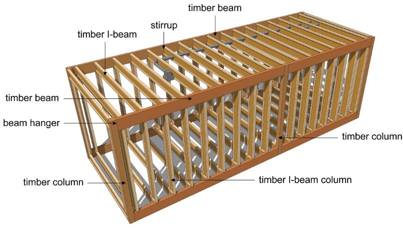
Sustainability 2020, 12, 8474                                                                                                                  5 of 20

   be individually plugged/unplugged from the shelf-structure without affecting the adjacent modules.
   This allows the Slab building to extend or shrink and the modules to be relocated. These operations
   can be executed at any time with the help of a crane. The modules can be reused or recycled at the end
   of the first service life, depending on their condition and material degradation. If reused, they could
   be sent back to the manufacturing plant to be refurbished and eventually refitted. The Slab building
   is intended
Sustainability    to12,
               2020, bex constructed in Luxembourg; therefore, the modules shall be designed to fit any 4 of 22
                         FOR PEER REVIEW
   orientation and location in Luxembourg to be flexible.

                                                                                                                1.20

                                                                                                                          4.20
                                                                OPEN CORRIDOR

                                                                                                                                  14.45
                                                                                                                          10.25
                                                                          9.00

                                      3.00      3.00       3.00          3.00          3.00              6.90

                                                  module                                           module

                                              installation of a module           removal of a module

                                                                                 (a)
                                                                                                                       OPEN CORRIDOR

                                                                                                                                          1.10
                                    0.80

         installation of a module
                                                                                                                        cable path

                                                                                                                                          3.60
                                    0.20

                                                                                                                  plug-in system to connect
                                                                                                                  the ducts and pipes
                                    3.50

                                                                                       3.50

                                                                                                                  for HVAC system
           module
                                                                         9.80
                                                                     STUDIO                                             OPEN CORRIDOR
                                    0.30

                                                                                                                                          1.10

            removal of a module
                                                                                                  0.60

                                                              rail
                                                                         9.00
                                                                                                                rainwater
                                                                                       2.70
                                    3.50

                                                                                                                                          2.70
                                                                                                  2.10

                    module
                                                                     STUDIO                                             OPEN CORRIDOR
                                       0.20

                                                                                                                                          1.10
                                    0.80

                                                              rail
                                                                         9.85

                                                                                 (b)

                                                                  Figure 1. Cont.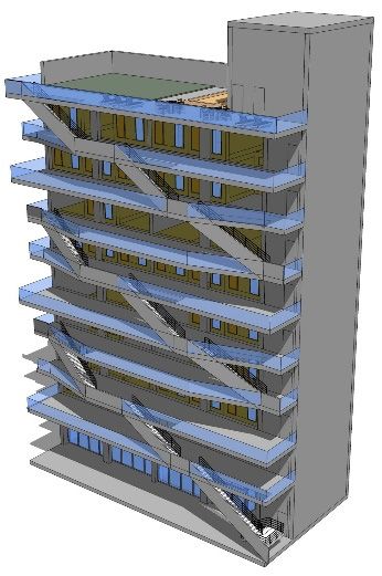
Sustainability 2020, 12, x FOR PEER REVIEW 5 of 22
Sustainability 2020, 12, 8474 6 of 20
Sustainability 2020, 12, x FOR PEER REVIEW 6 of 21
in Figure 2b. A non-glazed door of 0.9 m width and 2.1 m height is also located on the back facade.
The shelf-structure serves as docking space for the modules, provides building services including
HVAC, ensures both vertical and horizontal circulation and hosts the common utility rooms. Thanks
to a rail system, the modules can be individually plugged/unplugged from the shelf-structure
without affecting the adjacent modules. This allows the Slab building to extend or shrink and the
modules to be relocated. These operations can be executed at any time with the help of a crane. The
modules can be reused or recycled at the end of the first service life, depending on their condition
and material degradation. If reused, they could be sent back to the manufacturing plant to be
refurbished and eventually(c) refitted. The Slab building is intended to be constructed (d)in Luxembourg;
therefore,
Figure
the
Figure modules
1.1.Drawings
Drawings shall
and andbeviews
3D3D
designed
views ofto
of the thefitSlab
Slab
any building:
orientation
building:
and
(a)view
(a) Plan
location
Planof
view of in
theLuxembourg
the current current
floor;
to be
(b) floor;
Cross (b) Cross
flexible.
section
sectionofofthe current
the floor;
current (c) 3D
floor; (c) view of theoffront
3D view facade;facade;
the front (d) 3D (d)
view ofview
3D the back facade.
of the back facade.
2. Literature Review
Articles regarding thermal comfort assessment of modular constructions are scarce in literature.
Fifield et al. [17] conducted a summertime overheating assessment of thermally lightweight, well-
insulated, naturally ventilated modular healthcare buildings in the UK, according to British
standards. Depending on the usage of the rooms, British standards propose two methods to assess
overheating risk; (a) these are modelling and in-use monitoring. The method used in their study was in-
use monitoring, predicated on both static and adaptive overheating criteria. Static overheating
criteria are only based on indoor environmental factors, more specifically on indoor temperatures
(e.g., dry-resultant temperature, operative temperature, air temperature) in contrast with adaptive
criteria, which additionally consider personal factors. The most popular thermal comfort assessment
(c)
based on adaptive criteria is the American Society of Heating, Refrigerating and Air-Conditioning
Engineers (ASHRAE) (b) method. It proposes the predicted mean vote (PMV) model, under which the
highest comfort
Figure
Figure 2.2.3D temperature
3Dviews
views ofofthe
themodule:in (a)
module: winter
(a)Front and
facade;summer
Frontfacade; (b)
(b)Back are (c)
Backfacade;
facade; 24.3 °C and structure.
(c)Load-bearing
Load-bearing 26.7 °C (new effective
structure.
temperature), respectively [23]. Fifield et al. concluded that these modular buildings are at risk of
4.4. Methods overheating in a relatively cool UK summer condition.
Methods
summertime
Regarding
This
This section isplug-in
section isdivided
divided or
intoflexible
threethree
into mainmodular
parts.
main The units, no
partstudies
firstThe
parts. explains
first on
part thermal
theexplains
basis of thecomfort
the basis assessment
Luxembourgish
of the have
regulation
Luxembourgish regarding
been found in regulation overheating
literature; regarding risk
nonetheless, assessment on
few onesrisk
overheating residential
about buildings.
thermal on
assessment analysis,The second
which
residential part presents
are closely
buildings. The related to
the
secondsimulation
thermal comfort
part model
presents andsimulation
the the building
assessment, havemodelmodel.
been Thethethird
listed.
and Ulloa part
building et discusses
al. the simulation
[24] realized
model. The thirda part
study parameters.
on standard
discusses the 20-foot
simulation
equivalent parameters.
unit (TEU) shipping containers made of COR-TEN® steel, reused as service modules (first
4.1. Overheating Risk Assessment According to Luxembourgish Regulation
aid module, shower module and refrigeration module) in the area of humanitarian help or social
4.1. Overheating
On the basis
emergency. TheRisk Assessment
ofpurpose
the DIN 4108-2, According
of the the
study towas
Luxembourgish
Luxembourgish
to estimate Regulation
regulation
the peakon energy
for theperformance
heating and of residential
cooling demands
buildings [37,38] prescribes two methods regarding summertime thermal comfort. The first one is
in order
On thetobasischoose of thetheDIN adequate
4108-2, HVAC system for the
the Luxembourgish modules.
regulation Modules
on energy were studied
performance of in five
the checking of the minimum requirements for summer thermal protection, and the second one is
residential buildings [37,38] prescribes two methods regarding summertime
locations spread in different climate areas according to the Köppen–Geiger classification (equatorial, thermal comfort. The
the assessment of summertime overheating risk, requiring the realization of DTS to check a static
first
arid,one is the temperate,
warm checking of the minimum requirements for summer thermal protection, and the
wassecond
overheating criterion. Thesnow secondand polar
method, climates)
which is used[25], whereas
in this their
paper, involves orientation fixed (window
a ratio of “overheating
one is
facing the assessment
west). The of
thermalsummertime
analysis overheating
involved risk,
dynamic requiring
thermal the realization
simulations of DTS
(DTS) toTRNSYS
in check a software
period” (OP) over “exploitation period” (EP) where the overheating period is the time during which
static overheating criterion. The second method, which is◦ used in this paper, involves a ratio of
(v.17,
the Thermal Energy
free-running ambientSystemindoor Specialists,
temperatureLLC, exceeds Madison,
26 C. The WI,exploitation
USA) whereby periodmodules
has notgeometry
been was
“overheating period” (OP) over “exploitation period” (EP) where the overheating period is the time
modelled
further on Trimble
defined SketchUp.
in the regulation; The heating
however, and cooling[39]
DIN 4108-2:2013-2 demands
defines an of exploitation
the first aidperiod
module were
during which the free-running ambient indoor temperature exceeds 26 °C. The exploitation period
predicated
of 24/7. Hence, upon EN
if this ISO
ratio 13,790
is below [26]
10%,from the
summertimetemperatures range
thermal comfort
has not been further defined in the regulation; however, DIN 4108-2:2013-2 [39] defines an
which allows
is ensured. maintaining
Regarding the thermal
comfort forperiod
exploitation a hospital that
of 24/7. is from
Hence, 22 ratio
if this °C tois26 °C. Kosir
below et al. [27] conducted
10%, summertime a studyisto
thermal comfort evaluate energy
ensured.
and visual
Regarding the(daylight)
occupancyefficiency of a flexible
schedule, presented prefabricated
in Section 0, and themodular unit of
internal gains, 6.5 m length,
described 3.0 m width
in Section
0,and
the 3.4 m height. The
Luxembourgish moduledoes
regulation wasnot studied
dictateattofive
referdifferent
to a specific locations
standard. (Reykjavik, Hamburg, Munich,
Athens and Abu Dhabi) while varying different parameters, namely the orientation, the window-to-
4.2.
wallSimulation Model and
ratio (WWR), theBuilding
window Model
distribution, the shading, the thermal transmittance of the envelope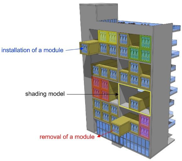
Sustainability 2020, 12, 8474 7 of 20
occupancy schedule, presented in Section 4.3.3, and the internal gains, described in Section 4.3.4,
the Luxembourgish regulation does not dictate to refer to a specific standard.
4.2. Simulation Model and Building Model
Sustainability 2020, 12, x FOR PEER REVIEW 7 of 21
Sustainability 2020,
DTS 12, xbeen
have FORrealized
PEER REVIEW 7 of 21
on TRNSYS software according to the simulation model shown in Figure 3.
Figure 3. TRNSYS model for DTS.
Figure 3. TRNSYS model for DTS.
The building model was created Figure 3. inTRNSYS
TRNBuild andforSketchup
model DTS. software. The module model
comprises a single thermal zone with residential building input
The building model was created in TRNBuild and Sketchup software. The module model characteristics. The comprises
module is
assimilated
The building
a single to amodel
thermal single-family
zone with house implemented
wasresidential
created in TRNBuild
building inputonand
a hosting
Sketchup
characteristics.site, The
which
software.is none
module The other
module than model
is assimilated the
to
shelf-structure.
comprises Module
a singlehouse
a single-family thermal walls can
zone with
implemented be adjacent to
on residential other
a hosting site, walls
building but
which isinputto consider the worst-case
characteristics.
none other layout,
The module
than the shelf-structure. all is
walls
assimilated
Module of to
the amodule
walls are assumed
single-family
can be adjacent house to implemented
to other be exposed
walls to the
on outdoor
but to consider a the
hosting influences. Theall
site, layout,
worst-case which building
is components
noneofother
walls the modulethan the
of the shelf-structure
shelf-structure.
are assumedModule create
walls to
to be exposed sun
can shading
thebeoutdoor
adjacenton the modules
to other The
influences. that
walls has to be considered.
but tocomponents
building consider the In this
ofworst-case regard, the all
layout,
the shelf-structure
wallsshading/insolation
create
of thesun shading
module arematrix
onassumed was generated
the modulesto bethat hasbytothe
exposed be 3D data geometry
to considered.
the outdoorIninfluences. mode, the
this regard, which
The requires the 3D
shading/insolation
building components
modelling of the shading. The shading model denoted in Figure 1c represents the worst-case sun
of the shelf-structure create sun shading on the modules that has to be considered. In thisshading.
matrix was generated by the 3D data geometry mode, which requires the 3D modelling of the regard, the
shading on a
The shading model module since
denoted this configuration exposes the most walls of the module to the sun; it
shading/insolation matrix wasingenerated
Figure 1c represents
by the 3D thedata
worst-case
geometry sun shading
mode,on a module
which since this
requires the 3D
corresponds
configuration toexposes
half of thethe current
most walls floor.of Note that a shear
the module to the wall
sun; is splitting the to
it corresponds current
half offloor into two
the current
modelling
parts.
of the
The 3D
shading.
sun shading
The shading
model of the
model denotedisinillustrated
shelf-structure
Figure 1cinrepresents
Figure 4.
thesurfaces
The
worst-case on of
the
sun
floor. Note that a shear wall is splitting the current floor into two parts. The 3D sun shading model
shading
top, on sides
the a module
and the since
backthis
facadeconfiguration exposes the most walls of the by module tothethewalls
sun; it
the shelf-structure is illustrated inof the model
Figure 4. Therepresent
surfaces onthetheshading
top, thegenerated
sides and theback
the slab,facade of
corresponds
the model represent the shading generated by the slab, the walls and the open corridors, respectively.two
and the to
open half of
corridors,the current floor.
respectively. As Note
the that
width a
ofshear
the wall
open is splitting
corridors is the
variable,current
the floor
smallest into
width
parts. The
(1.20
As m)
the 3Dwassuntaken.
width ofshading
the openmodel of the
corridors shelf-structure
is variable, the smallestis illustrated
width (1.20 in m)Figure 4. The surfaces on the
was taken.
top, the sides and the back facade of the model represent the shading generated by the slab, the walls
and the open corridors, respectively. As the width of the open corridors is variable, the smallest width
(1.20 m) was taken.
(a) (b)
Figure
Figure 4.
4.3D
3Dsun
sunshading
shading model
model of
of the
the shelf-structure onthe
shelf-structure on themodule:
module:(a)
(a)Front
Frontfacade;
facade;(b)
(b)Back
Backfacade.
facade.
The minimum
The minimumrequired wall thicknesses
required were determined
wall thicknesses in accordance
were determined inwith the Luxembourgish
accordance with the
regulation on energy
Luxembourgish (a)performance
regulation of residential
on energy performancebuildings and based
of residential buildings(b)
on the worst-case
and orientation
based on the worst-
case orientation (window facing north), which makes the module variants very well thermally
Figure 4. 3D sun shading model of the shelf-structure on the module: (a) Front facade; (b) Back facade.
insulated. For the current requirements for building permit application, characteristics of walls,
windows and door are similar to those found in typical low energy houses. For the requirements for
The minimum required wall thicknesses were determined in accordance with the
AAA energy class, characteristics of these components were set to very high performance.
Luxembourgish regulation on energy performance of residential buildings and based on the worst-
case orientation (window facing north), which makes the module variants very well thermally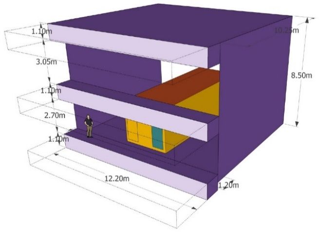
Sustainability 2020, 12, 8474 8 of 20
(window facing north), which makes the module variants very well thermally insulated. For the current
requirements for building permit application, characteristics of walls, windows and door are similar to
those found in typical low energy houses. For the requirements for AAA energy class, characteristics of
these components were set to very high performance.
4.2.1. Opaque Walls on the Module Envelope
Sustainability 2020, 12, x FOR PEER REVIEW 8 of 21
Basically, the six sides of the module envelope have the same structure. However, additional elements
could
calculationseventually
have shownbe added,
that such
a wallas athickness
heating floor system,
of 40 cm isfor instance. to
sufficient Energy
fulfilbalance
the two calculations
requirements
have shown that a wall thickness of 40 cm is sufficient to fulfil the two requirements explained in
explained in Section 0. For the AAA energy class requirements, 31 cm of aerogel is required, resulting
Section 4.2. For the AAA energy class requirements, 31 cm of aerogel is required, resulting in a wall
in a wall U-value of 0.062 W/m2.K. For the current requirements for building permit application, 31
U-value of 0.062 W/m2 .K. For the current requirements for building permit application, 31 cm of wood
cm of wood wool is sufficient, giving a wall U-value of 0.123 W/m2.K. An additional layer of 5 cm
wool is sufficient, giving a wall U-value of 0.123 W/m2 .K. An additional layer of 5 cm lightweight
lightweight
concreteconcrete
was applied wason applied on and
the walls the walls andofthe
the floor thefloor
fictiveofmodule
the fictive module
version, version,
fulfilling fulfilling
the AAA
the AAA
energyenergy requirements,
requirements, and this isand this difference
the only is the only difference
between between
the fictive and thethe fictive
current and the
versions; current
hence,
versions; hence, wall U-value of the fictive module version remains
2 at 0.062 W/m 2.K. The structure of
wall U-value of the fictive module version remains at 0.062 W/m .K. The structure of the module walls
the module
for both walls
variantsforisboth variants
illustrated is illustrated
in Figure 5. in Figure 5.
Figure
Figure5.5.Structure
Structure of the
the module
modulewalls.
walls.
Characteristics
Characteristics of materialson
of materials onthe
theopaque
opaque walls
walls of
ofthe
themodule
moduleenvelope areare
envelope given in Table
given 1.
in Table 1.
Table 1. Characteristics of materials on the opaque walls of the module envelope.
Table 1. Characteristics of materials on the opaque walls of the module envelope.
Heat Conductivity Heat Capacity Density
Building Material Heat Conductivity Wh/(kg.K)
Heat Capacity Density
Building Material W/(m.K) (kg/m3 )
W/(m.K) Wh/(kg.K) (kg/m3)
Chipboard * 0.14 0.47 500
Chipboard
Aerogel* a [40] 0.020.14 0.28 0.47 150 500
Aerogel a [40] [41]
Wood wool b 0.040.02 0.58 0.28 50 150
WoodWood b [41]
woolfiberboard * 0.090.04 0.69 0.58 650 50
Air blade *c, *
Wood fiberboard 0.030.09 0.28 0.69 1.23 650
Hardwood
Air blade c,* * 0.180.03 0.44 0.28 700 1.23
Softwood * 0.14 0.61 450
Hardwood * d, 0.18 0.44 700
Lightweight concrete * 1.80 0.28 1400
Softwood * 0.14 0.61
a Used in the module variant fulfilling the requirements for AAA energy class. b Used in the module variant
450
Lightweight concrete for
fulfilling the requirements
d,* building permit application.
1.80 c The value of the heat 0.28 1400
conductivity varies according
to the thickness and the exchange with external.d Used in the fictive module versionclass.
of the bvariant
aUsed in the module variant fulfilling the requirements for AAA energy Usedfulfilling the
in the module
requirements for AAA energy class. * Source of the values: Lesosai software database.
variant fulfilling the requirements for building permit application. The value of the heat conductivity
c
varies according to the thickness and the exchange with external. d Used in the fictive module version
of the variant fulfilling the requirements for AAA energy class. * Source of the values: Lesosai
software database.
Table 1 indicates that both module variants have a relatively low thermal inertia but the module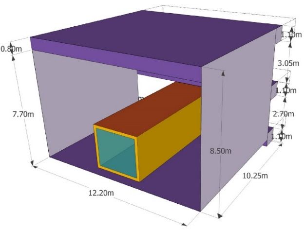
Sustainability 2020, 12, 8474 9 of 20
Table 1 indicates that both module variants have a relatively low thermal inertia but the module
variant fulfilling the requirements for building permit application has a slightly higher thermal mass.
4.2.2. Transparent Walls on the Module Envelope
Characteristics of the transparent walls of the module envelope are given in Table 2.
Table 2. Characteristics of the transparent walls on the module envelope.
Module Variant
Components
Building Permit Application AAA Energy Class
Glazing and frame:
Uglazing 1.10 W/(m2 .K) 0.55 W/(m2 .K)
g-value 60% 60%
Uframe 1.10 W/(m2 .K) 0.70 W/(m2 .K)
Non-operable window:
Gross dimensions (width × height) 0.90 m × 2.10 m 0.90 m × 2.10 m
Surface ratio glazing/window 70% 80%
Uinstalled 1.21 W/(m2 .K) 0.65 W/(m2 .K)
Window
Gross dimensions (width × height) 3.00 m × 2.70 m 3.00 m × 2.70 m
Opening Tilt and turn window Tilt and turn window
Gross dimensions of the operable part (width × height) 3.00 m × 1.20 m 3.00 m × 1.20 m
Surface ratio glazing/window 75% 80%
Uinstalled 1.20 W/(m2 .K) 0.64 W/(m2 .K)
4.3. Simulation Parameters
4.3.1. Simulation Period and Weather Data File
The selected simulation period is from the 1 of June to the 31 of August, accounting for 2184 h.
Luxembourg is situated in Western Europe, between Belgium, France and Germany. The country
is divided into two regions: the Oesling in the north (225–559 m above sea level) and the Gutland
in the south (133–440 m above sea level). Despite the altitude difference between the two regions,
Luxembourg climate is relatively homogeneous, and is classified as Cfb, i.e., warm temperate climate
with fully humid precipitation and warm summer temperature according to the Köppen–Geiger world
climate map [25]. The weather data file “DE-Trier-106090.tm2” was used, given that Luxembourg has
similar weather conditions to the German city Trier (latitude 49.75◦ N, longitude 6.67◦ E), which is just
15 km from the national border. The altitude of the weather station and the Slab building are 278 m and
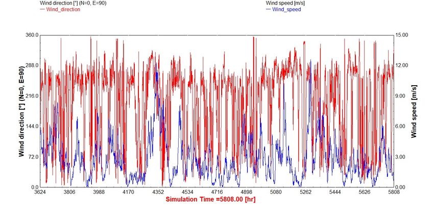
133 m (lowest altitude in Luxembourg), respectively. The curves of temperature and relative humidity
are presented in Figure 6, the curves of wind direction and wind speed—Figure 7, the curves of
global horizontal radiation and direct normal radiation—Figure 8. The values of the global horizontal
radiation and the direct normal radiation are not interpolated.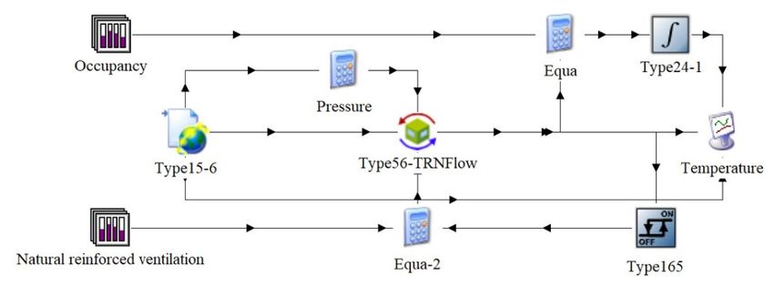
Luxembourg has similar weather conditions to the German city Trier (latitude 49.75°N, longitude
  6.67 E), which is just 15 km from the national border. The altitude of the weather station and the Slab
  building are 278 m and 133 m (lowest altitude in Luxembourg), respectively. The curves of
  temperature and relative humidity are presented in Figure 6, the curves of wind direction and wind
  speed—Figure
Sustainability        7,8474
               2020, 12, the curves of global horizontal radiation and direct normal radiation—Figure 8.10
                                                                                                        Theof 20
  values of the global horizontal radiation and the direct normal radiation are not interpolated.

  Sustainability 2020, 12, x FOR PEER REVIEW                                                          10 of 21
  Sustainability 2020, 12, x FOR PEER REVIEW                                                          10 of 21

                                    Figure 6. Temperature
                                    Figure    Temperature and relative
                                                          andrelative  humidity.
                                                              relativehumidity.
                                                                       humidity.
                                    Figure 6. Temperature and

                                       Figure 7. Wind direction and wind speed.
                                      Figure  7. Wind direction
                                      Figure 7.       direction and
                                                                andwind
                                                                    windspeed.
                                                                          speed.

                         Figure8.8.Global
                        Figure     Global horizontal
                                          horizontal radiation and direct
                                                     radiation and directnormal
                                                                           normalradiation.
                                                                                  radiation.
                         Figure 8. Global horizontal radiation and direct normal radiation.

  4.3.2. Occupancy Scenarios and Mechanical Ventilation Airflow
  4.3.2. Occupancy Scenarios and Mechanical Ventilation Airflow
        A high and a low occupancy scenario were studied to consider possible worst-case scenarios.
        A high and a low occupancy scenario were studied to consider possible worst-case scenarios.
  For the high occupancy scenario, the studio is occupied by two persons at all times, whereas for the
  For the high occupancy scenario, the studio is occupied by two persons at all times, whereas for the
  low occupancy scenario, it is unoccupied from 9 a.m. to 6 p.m. on weekdays as well as on weekends.
  low occupancy scenario, it is unoccupied from 9 a.m. to 6 p.m. on weekdays as well as on weekends.
                                                                                               3
Sustainability 2020, 12, 8474 11 of 20
4.3.2. Occupancy Scenarios and Mechanical Ventilation Airflow
A high and a low occupancy scenario were studied to consider possible worst-case scenarios.
For the high occupancy scenario, the studio is occupied by two persons at all times, whereas for the
low occupancy scenario, it is unoccupied from 9 a.m. to 6 p.m. on weekdays as well as on weekends.
When the room is occupied, the mechanical ventilation provides an airflow of 60 m3 /h, based on an
airflow per person of 30 m3 /h. When the room is unoccupied, the mechanical ventilation provides a
minimum hygienic air change rate of 0.35 h−1 corresponding to an airflow of 23.6 m3 /h, as required by
Luxembourgish regulation. For the two occupancy scenarios, the exploitation period is 2184 h.
4.3.3. Internal Gains
The CIBSE TM59:2017 [42] was used as reference in this work as it proposes internal gain values
applicable to studios
Sustainability 2020, following
12, x FOR a well-defined profile. In CIBSE TM59:2017, the occupancy to consider
PEER REVIEW 11 of 21
corresponds to two people occupying the studio at all times on weekdays as well as on weekends.
switched on from
The total peak load6fromp.m.people
to 11 p.m.
is 150with
W ofa sensible
load valueheatofand
2 W/m
110 2Wofofnet floorheat.
latent area,Lighting
thus, 54isW for the
switched
studio
on from of627 m .to
p.m. 2 The11 equipment
p.m. with apeak load load
valueisofassumed 2
2 W/m from of net6 floor
p.m. area,
to 8 p.m.
thus,with
54 Wa for
value
theof 450 W,
studio of
200 2
27 mW. from 8 p.m. to 10
The equipment p.m.,
peak load110is W from 9from
assumed a.m. 6top.m.
6 p.m.to 8and
p.m. from
with10a p.m.
valuetoof12 p.m.,
450 andWa from
W, 200 base
load
8 p.m. ofto
8510Wp.m.,
for the
110rest of the9 day.
W from a.m. Noto 6equipment
p.m. and from load10is p.m.
considered when
to 12 p.m., thea room
and is unoccupied.
base load of 85 W for
The internal
the rest of thegains
day. Noprofile on a daily
equipment loadbasis for the two
is considered occupancy
when the room scenarios is illustrated
is unoccupied. in Figure
The internal gains9.
In the summer
profile on a daily period, thethe
basis for heating system will
two occupancy be turned
scenarios off and theinsupply
is illustrated Figureair
9. will besummer
In the the outside air
period,
without
the heatinganysystem
handling. will be turned off and the supply air will be the outside air without any handling.
800 800
Sensible heat load (W)
Sensible heat load (W)
600 150 600 150
54 54
400 400
150 150
200 450 54 150 200 450 54 150
150 150 150 150 150
200 54 0 0 200 54 0
0 110 110 0 110 110 110
85 85
0 0 0
0-9 9-18 18-20 20-22 22-23 23-24 0-9 9-18 18-20 20-22 22-23 23-24
Hour Hour
Equipment Lighting People Equipment Lighting People
(a) (b)
Figure 9. Internal
Internalgains
gainsprofile
profile
onon a daily
a daily basis:
basis: (a) Low
(a) Low occupancy
occupancy scenario;
scenario; (b) High(b) High occupancy
occupancy scenario.
scenario.
4.3.4. Sub-Variants
4.3.4.Three
Sub-Variants
sub-variants, S1, S2 and S3, defined according to different shading device configurations,
wereThree
set upsub-variants,
for each module variant
S1, S2 mentioned
and S3, defined previously
according to in different
Section 1.shading
S1 involves no configurations,
device shading device,
S2—a set
were fixedupexternal
for each shading
module device and mentioned
variant S3—a moveable externalinshading
previously Sectiondevice. The external
0. S1 involves shading
no shading
device was
device, S2—a chosen
fixedfor its higher
external effectiveness
shading in comparison
device and to the internal
S3—a moveable externalsince the material
shading and
device. The
the dimensions are identical [43]. An external shading device will be implemented
external shading device was chosen for its higher effectiveness in comparison to the internal since the on all transparent
walls. The
material S2 the
and sub-variant
dimensionscan also be assimilated
are identical to the
[43]. An case where
external the user
shading does
device not
will beadjust the shading
implemented on
device on purpose or by omission. For this sub-variant, the shading factor was arbitrarily
all transparent walls. The S2 sub-variant can also be assimilated to the case where the user does not set to a fixed
value ofthe
adjust 50% at all times
shading deviceas on
notpurpose
to compromise daylight penetration.
or by omission. For the S3 the
For this sub-variant, sub-variant, the control
shading factor was
of the external
arbitrarily set toshading
a fixeddevice
value ofis automated, according
50% at all times as nottotothe global radiation
compromise daylighton penetration.
window, i.e.,Foron the
facade.
S3 The upper
sub-variant, theradiation
control threshold values found
of the external shadingin literature
device isdepend on theaccording
automated, orientationtoand
theclimatic
global
conditionson[44].
radiation Newsham
window, [45]the
i.e., on conducted
facade. Thea study
upper onradiation
the implication of manual
threshold controlinofliterature
values found window
blinds on
depend oncomfort and energy
the orientation andconsumption for the climate
climatic conditions of Toronto
[44]. Newsham (Canada).
[45] conducted Heaidentified
study on thatthe
the radiation value at which most users operated the blinds was 233 W/m 2 . Lee et al. [46] suggested
implication of manual control of window blinds on comfort and energy consumption for the climate
a value
of Torontoof 200 W/m2 in
(Canada). Hea identified
study about thethe
that evaluation
radiation of thermal
value and lighting
at which most users energy performance
operated the blindsof
was 233 W/m2. Lee et al. [46] suggested a value of 200 W/m2 in a study about the evaluation of thermal
and lighting energy performance of shading devices on kinetic facades for the climate of Dubai
(UAE). Wankanapon [47] found a value of 189 W/m2 for a white roller shade allowing to save cooling
energy from 21 to 27% for the climate of Minneapolis (USA). Therefore, the default values of radiation
threshold set in TRNBuild were chosen for the simulations, whereby the shading device closes aboveSustainability 2020, 12, 8474 12 of 20
shading devices on kinetic facades for the climate of Dubai (UAE). Wankanapon [47] found a value of
189 W/m2 for a white roller shade allowing to save cooling energy from 21 to 27% for the climate of
Minneapolis (USA). Therefore, the default values of radiation threshold set in TRNBuild were chosen
for the simulations, whereby the shading device closes above 180 W/m2 and opens bellow 160 W/m2 .
For each sub-variant, three different ventilation scenarios are proposed. The first one is without natural
reinforced ventilation, the second one with night natural ventilation from 10 p.m. to 7 a.m. and the
third one with day and night natural reinforced ventilation. Natural reinforced ventilation will be
operated automatically by window opening; the window closes when the room temperature drops to
19 ◦ C and opens at over 22 ◦ C.
4.3.5. Air Exchange
Sustainability Rates
2020, 12, x FOR PEER REVIEW 12 of 21
Since the lowest atmospheric pressure is found at the lowest altitude, the module located at
TRNFlow
the lowestaccording to the network
level (worst-case) model
was chosen for theillustrated
simulation.inThe
Figure 10a. Therates
air exchange “heights of link” of the
were simulated
different airflow
on TRNFlow network
according to components on theillustrated
the network model Slab building are illustrated
in Figure in Figure
10a. The “heights 10b. of the
of link”
different airflow network components on the Slab building are illustrated in Figure 10b.
0.90
3.10
9.15
6.05
(a) (b)
Figure
Figure10.
10. Model and drawing
Model and drawingused
usedonon TRNFlow:
TRNFlow: (a) (a) Network
Network model
model on TRNFlow
on TRNFlow [48];
[48]; (b) (b) Heights
Heights
of the different airflow components on the Slab building.
of the different airflow components on the Slab building.
No auxiliary node or ducts were modeled as the supply and extract airflow were assumed to be
No auxiliary node or ducts were modeled as the supply and extract airflow were assumed to be
independent of the pressure difference. A tilt opening was considered for the window. If the maximum
independent of the pressure difference. A tilt opening was considered for the window. If the
opening corresponds to an opening factor of 1, a value of 0.25 is chosen to avoid eventual high air
maximum opening corresponds to an opening factor of 1, a value of 0.25 is chosen to avoid eventual
velocity on natural ventilation. No natural reinforced ventilation is operating when the room is
high air velocity
unoccupied. on natural
Regarding the ventilation. No
air infiltration naturalthe
through reinforced ventilation
module envelope, is operating when
Luxembourgish standardthe room
isprescribes
unoccupied. Regarding the air infiltration through the
−1 module −1 envelope, Luxembourgish
exchange rates at 50 Pa (n50 or ACH50) of 0.6 h and 1 h for the module variant fulfilling standard
prescribes exchange
the AAA energy classrates at 50 Pa and
requirements (n50the
orone
ACH50) of 0.6
fulfilling h and 1permit
−1
the building h forapplication
−1 the module variant fulfilling
requirements,
the AAA energy
respectively. class the
To simplify, requirements
air infiltrationand the one
is assumed fulfilling
to occur the building
only through permit
the cracks aroundapplication
the
requirements,
windows and the respectively. To simplify,
door. In TRNFlow, the air the air infiltration
exchange rates have is assumed
to be entered to occur
in kg/s at 1only through
Pa and for the
that, the
cracks powerthe
around law model of and
windows airflow
thethrough
door. Inorifice
TRNFlow,can bethe
usedairtoexchange
estimate the airflow
rates haveattodifferent
be entered in
pressures, since there is a linear correlation between pressure difference and airflow.
kg/s at 1 Pa and for that, the power law model of airflow through orifice can be used to estimate The power law the
equation of airflow through orifice is given by the following formula [49,50]:
airflow at different pressures, since there is a linear correlation between pressure difference and
airflow. The power law equation of airflow through orifice is given by the following formula [48,50]:
= ∗∆ , (1)
where is the airflow expressed in m3/s, is the air leakage coefficient, ∆ is the pressure
difference and is the pressure exponent. Most cracks have a mixed flow regime with a flow
exponent of 0.6 to 0.7 [48], therefore, a value of 0.65 was chosen. An air density of 1.2 kg/m3 was
considered to determine the air mass flow. Table 3 presents the determination of the air mass flow atSustainability 2020, 12, 8474 13 of 20
Q = C ∗ ∆Pn , (1)
where Q is the airflow expressed in m3 /s, C is the air leakage coefficient, ∆P is the pressure difference
and n is the pressure exponent. Most cracks have a mixed flow regime with a flow exponent of 0.6 to
0.7 [48], therefore, a value of 0.65 was chosen. An air density of 1.2 kg/m3 was considered to determine
the air mass flow. Table 3 presents the determination of the air mass flow at 1 Pa (Q1).
Table 3. Determination of the airflow at 1 Pa (Q1).
Module Variants n V (m3 ) ACH50 (h−1 ) Q50 (m3 /h) C Q1 (m3 /h) Q1 (kg/s)
AAA energy class 0.6 43.74 3.43 3.43 11.4 × 10⁻⁴
0.65 72.9
Building permit application 1 72.90 5.73 5.73 19.1 × 10⁻⁴
The air mass flow coefficient Cs is assumed to be commensurate with the crack length. Table 4
presents the determination of the air mass flow coefficient Cs at 1 Pa for each crack.
Table 4. Determination of the air mass flow coefficient Cs at 1 Pa for each crack.
Air Mass Flow Coefficient Cs (kg/s)
Cracks around the
Length (m) “AAA Energy Class” “Building Permit
Element
Module Application” Module
Door 6 (26%) 2.9 × 10⁻⁴ 4.9 × 10⁻⁴
Non-operable window 6 (26%) 2.9 × 10⁻⁴ 4.9 × 10⁻⁴
Window 11.4 (48%) 5.6 × 10⁻⁴ 9.3 × 10⁻⁴
Total 23.4 (100%) 11.4 × 10⁻⁴ 19.1 × 10⁻⁴
The wind pressure acting on the facades was taken into account and the wind pressure coefficients
Cp were defined, as shown in Table 5, section External nodes. Data and parameters entered on
TRNFlow are also presented in Table 5.
Table 5. Data and parameters entered on TRNFlow.
Parameters Values
Dual flow ventilation system
Supply/extract airflow (imposed)
- Room unoccupied 0.35 [1/h] = 23.6 m3 /h
- Room occupied 60 m3 /h
Air density at Test Conditions 1.2 kg/m3
Air Mass Flow Coefficient Cs (if fan is turned off) 0.2 kg/s at 1 Pa
Air Flow Exponent n (if fan is turned off) 0.65 a
Height of link relative to “From-Node” 9.15 m
Height of link relative to “To-Node” 3.10 m
Thermal airnode
Reference height 6.05 m
Airnode interior dimensions: height / depth 2.70 m/9.00 mSustainability 2020, 12, 8474 14 of 20
Table 5. Cont.
Parameters Values
External nodes
Reference height of Cp-values 9.15 m
Wind direction angle:
Length-to-width ratio: 2:1
Shielded (worst-case based on DTS)
0◦ =−0.32; 45◦ =−0.3; 90◦ =0.15; 135◦ =0.18; 180◦ =0.15;
- EN001: wind from south-west (front façade):
225◦ =−0.3; 270◦ =−0.32; 315◦ =−0.2 [51]
0◦ =0.15; 45◦ =−0.3; 90◦ =−0.32; 135◦ =−0.2; 180◦ =−0.32;
- EN002: Wind from north-east (back façade):
225◦ =−0.3;270◦ =0.15; 315◦ =0.18 [51]
Crack around the door/non-operable window
Air Mass Flow Coefficient Cs 2.9 × 10⁻⁴ kg/s at 1 Pa (“AAA energy class” module)
4.9 × 10⁻⁴ kg/s at 1 Pa (“Building permit application” module)
Air Flow Exponent n 0.65 a
Height of link relative to “From-Node” 6.05 m
Height of link relative to “To-Node” 0m
Connected to external node EN002
Crack around the window
Air Mass Flow Coefficient Cs 5.6 × 10⁻⁴ kg/s at 1 Pa (“AAA energy class” module)
9.3 × 10⁻⁴ kg/s at 1 Pa (“Building permit application” module)
Air Flow Exponent n 0.65 a
Height of link relative to “From-Node” 6.05 m
Height of link relative to “To-Node” 0m
Connected to external node EN001
Window opening
Own height factor 1 (window is in a vertical wall)
Category of opening Bottom hinged sash window/door
Max. width/height of opening 2.75 m / 1.05 m
Height of pivoting axis (A-height) 0.90 m
Discharge coefficient Cd1
b (completely closed) 0.6
Discharge coefficient Cd2
b (completely opened) 0.6
For Closed Opening:
- Flow coefficient Cs per m crack length 0 kg/s/m at 1 Pa as described in Section 4.3.5
- Flow exponent n 0.65 a
Opening factor of window maximum value of 0.25
Connected to external node EN001
Height of link relative to “From-Node” 6.95 m
Height of link relative to “To-Node” 0.90 m
Wind velocity profile
Wind angle direction 0◦
Wind velocity exponent of building location 0.25 (wood, small city, suburb)
aMost cracks have a mixed flow regime with a flow exponent n of 0.6 to 0.7 so the default value of 0.65 is taken. b For
usual situations, a Cd value of 0.6 to 0.7 can be found very often in literature, so the default value of 0.6 is taken.
5. Results and Discussion
DTS showed that the worst-case orientation is window facing south-west, which was taken as
reference for the results presented below. Table 6 presents the overheating periods of the two module
variants for the low and the high occupancy scenarios according to two overheating criteria (>28 ◦ C
and >26 ◦ C).Sustainability 2020, 12, 8474 15 of 20
Table 6. Overheating periods of the two module variants for the low and high occupancy according to different overheating criteria.
Low Occupancy High Occupancy
Overheating Criteria ACH * Overheating Criteria ACH *
Module Variants and Sub-Variants >28 ◦ C >26 ◦ C Max. Room [h−1 ] >28 ◦ C >26 ◦ C Max. Room [h−1 ]
Temp. [◦ C] Temp. [◦ C]
OP OP OP/EP ODH OP OP OP/EP ODH
Mean Max Mean Max
[hrs.] [hrs.] [%] [◦ Ch] [hrs.] [hrs.] [%] [◦ Ch]
“AAA energy class“ module
S1: Without any external shading device
- without natural reinforced ventilation 2135 2148 98 22,667 52 0.68 0.96 2142 2151 98 23,745 52 0.88 0.96
- with night natural reinforced ventilation 810 1146 52 4732 44 1.87 5.20 954 1285 59 5987 46 2.12 5.25
- with day and night natural reinforced ventilation 496 816 37 2450 40 2.38 5.07 351 649 30 1716 38 3.41 4.70
S2: With a fixed external shading device
- without natural reinforced ventilation 1484 1927 88 7787 40 0.67 0.95 1781 2081 95 10,810 40 0.86 0.95
- with night natural reinforced ventilation 218 505 23 872 35 1.60 4.86 424 792 36 1817 37 1.89 4.85
- with day and night natural reinforced ventilation 113 284 13 422 33 1.98 4.47 162 337 15 608 34 2.87 4.53
S3: With a moveable external shading device
- without natural reinforced ventilation 678 1249 57 2487 33 0.66 0.95 1233 1723 79 5348 35 0.86 0.95
- with night natural reinforced ventilation 28 151 7 105 30 1.42 4.38 159 416 19 546 32 1.75 4.60
- with day and night natural reinforced ventilation 8 79 4 35 29 1.73 4.30 45 188 9 163 31 2.69 4.40
“Building permit application“ module
S1: Without any external shading device
- without natural reinforced ventilation 1464 1788 82 9457 46 0.68 1.03 1611 1915 88 11,134 47 0.87 1.03
- with night natural reinforced ventilation 601 896 41 3115 42 1.68 4.99 737 1044 48 4103 44 1.93 5.05
- with day and night natural reinforced ventilation 378 649 30 1847 38 2.14 4.81 302 565 26 1477 37 3.08 4.40
S2: With a fixed external shading device
- without natural reinforced ventilation 504 858 39 2079 36 0.67 1.03 764 1232 56 3544 38 0.86 1.03
- with night natural reinforced ventilation 124 308 14 486 34 1.40 4.12 234 516 24 1011 36 1.69 4.52
- with day and night natural reinforced ventilation 77 213 10 290 32 1.71 4.31 131 267 12 478 33 2.50 4.50
S3: With a moveable external shading device
- without natural reinforced ventilation 95 422 19 376 31 0.67 1.02 378 732 33 1257 33 0.86 1.02
- with night natural reinforced ventilation 7 82 4 34 29 1.21 4.13 66 255 12 242 31 1.55 4.33
- with day and night natural reinforced ventilation 3 47 2 17 29 1.43 4.17 24 147 7 101 30 2.16 4.24
OP/EP means ratio “overheating period” over “exploitation period”. ODH means overheating degree-hours. * The ACH corresponds to the overall air change rate taking into account the
air infiltration, the mechanical ventilation and the natural ventilation.You can also read