SHADOWCLAD SPECIFICATION & INSTALLATION GUIDE
←
→
Page content transcription
If your browser does not render page correctly, please read the page content below
SHADOWCLAD                                                ®

                      SPECIFICATION
                      & INSTALLATION
                      GUIDE
                      FOR CAVITY CONSTRUCTION
                      MARCH 2021

Information contained within is specific to Shadowclad® structural plywood products and must not be used
with any other plywood products, no matter how similar they may appear.
CAVITY CONSTRUCTION

Contents
1.0     Shadowclad® Product Range................................. 3
1.1     Technical Information & CAD Details................. 4
1.2     Product Description & Range............................... 4
1.3     Building Materials for Use with Shadowclad
        (Exterior Cladding)................................................... 10
1.4  Preservative Treatment...................................... 10
1.5  Sustainability ....................................................... 11
1.6  Product Identification.......................................... 11
2.0  Design Considerations........................................ 11
2.1  Design Responsibility.......................................... 11
2.2  Literature Scope.................................................. 11
2.3  Code Compliance............................................... 11
2.4  Site & Foundations.............................................. 11
2.5  Ground Clearances............................................. 12
2.6  Moisture Management........................................ 12
2.7  Wind Loading...................................................... 12
2.8  Durability............................................................. 12
2.9  Textured vs. Smooth Finished Plywood as
     Exterior Cladding................................................ 12
2.10 Health & Safety.................................................... 13
2.11 Storage & Handling............................................. 13
3.0 Interior Linings..................................................... 13
4.0 Installation – Exterior Cladding.......................... 14
4.1 Framing – Durability............................................ 14
4.2 Framing – Construction...................................... 14
4.3 Preparation – Building Underlay & Rigid Air
     Barrier.................................................................. 14
4.4 Preparation – Cavity Construction.................... 14
4.5 Sheet Layout ....................................................... 17
4.6 Fixings – Fastener Durability............................... 17
4.7 Fixings – Fastener Size & Layout........................ 17
4.8 Installation Tools for Shadowclad....................... 18
4.9 Shadowclad Key Installation & Design Points.... 19
4.10 Vertical Sheet Joints............................................ 20
4.11 Horizontal Sheet Joints....................................... 23
4.12 External Corners................................................. 25
4.13 Internal Corners.................................................. 26
4.14 Shadowclad Flashing Junction Points.................. 27
4.15 Window Penetrations......................................... 29
4.16 Wall Penetrations................................................ 32
4.17 Sheet Clearances................................................. 36
4.18 Other Details....................................................... 39
5.0 Coating & Application – Exterior Cladding....... 45
5.1 Surface Preparation............................................. 45
5.2 Coating Application............................................ 45
5.3 Coating Selection................................................ 45
5.4 Coating Requirements if Run off is Used for
     Drinking Water................................................... 46
6.0 Maintenance........................................................ 47
7.0 Frequently Asked Questions.............................. 48
8.0 Glossary of Terms.............................................. 48
9.0 References & Sources of Information................ 49
10.0 Limitations........................................................... 49
11.0 Shadowclad Stick User Guide ............................ 50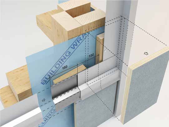
SHADOWCLAD® INSTALLATION - FOR CAVITY CONSTRUCTION
1.0 SHADOWCLAD® PRODUCT RANGE
Manufactured in New Zealand by Carter Holt Harvey Plywood (CHH Ply), Shadowclad®
panels are suitable for use as an exterior wall cladding when using H3 treated panels or as an
internal wall or ceiling lining when using untreated panels.

Shadowclad is manufactured under a third party audited quality control programme to
monitor compliance with AS/NZS 2269 Plywood Structural. All Shadowclad products carry
Engineered Wood Products Association of Australasia (EWPAA) Joint Accreditation System –
Australia and New Zealand (EWPAA/JAS-ANZ) certification.

Shadowclad has been BRANZ appraised as a cladding material for cavity wall construction. To
view the BRANZ Appraisal No. 764 (2017) visit www.shadowclad.co.nz.

For specific information regarding the use of Shadowclad with weatherboard, solid plaster or
brick vertical junctions refer to the Shadowclad Specification and Installation Guide for mixed
cladding systems on cavity construction.

Our other plywood products:

• For specific information on plywood as a rigid air barrier, and/or bracing, refer to the current
  Ecoply® Barrier Specification and Installation Guide.
• For information relating to Ecoply structural plywood and applications other than exterior
  cladding, refer to the current Ecoply Specification and Installation Guide.

These are all available for download from www.chhply.co.nz.

The Shadowclad for cavity construction BRANZ Appraisal No. 764 (2017) does not cover:

• Shadowclad used as an interior lining.
• Handiply® Utilityclad™ plywood products.
• Shadowclad in direct fix cladding applications.

Shadowclad products must be competently installed in accordance with good building
practices and sound design principles to satisfy the requirements of the Building Act 2004,
the New Zealand Building Code (NZBC), and applicable New Zealand Standards. This is
the responsibility of building owners and the design professionals and builders that they
engage. This Shadowclad Specification and installation guide for cavity construction contains
information, limitations, and cautions regarding the properties, handling, installation, usage, and
the maintenance of Shadowclad products. However, to the maximum extent permitted by law,
CHH Ply assumes no legal liability to you in relation to this information.

The information contained in this document is current as at March 2021. It is your responsibility to
ensure you have the most up to date information available.

The information contained in this publication relates specifically to Shadowclad structural plywood
products manufactured by CHH Ply and must not be used with any other plywood manufacturer’s
products no matter how similar they may appear.

Alternative plywood products can differ in a number of ways which may not be immediately obvious and
substituting them for Shadowclad structural plywood products is not appropriate, and could in extreme
cases lead to premature failure and/or buildings which do not meet the requirements of the NZBC.

         CHH PLY | SHADOWCLAD® CAVITY CONSTRUCTION | 0800 326 759 | www.shadowclad.co.nz                                  3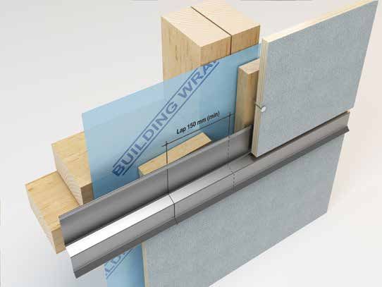
1 . 1 T E C H N I C A L I N F O R M AT I O N & C A D D E TA I LS
SHADOWCLAD® INSTALLATION - FOR CAVITY CONSTRUCTION
When specifying or installing any Shadowclad product visit For buildings containing mixed cladding solutions with
www.shadowclad.co.nz or call 0800 326 759 to ensure you have Shadowclad refer Shadowclad Specification and Installation
current specification material and any relevant technical notes. Guide for mixed cladding systems on cavity construction.
Having trouble installing Shadowclad? Visit www.shadowclad.co.nz or download the Shadowclad APP to view
the installation animations of common Shadowclad junctions.
1 . 2 P RO D U C T D E S C R I P T I O N & R A N G E
Shadowclad structural plywood panels are manufactured from Shadowclad Ultra features a factory applied exterior grade
radiata pine wood veneers. The veneers are placed at right angles performance coating suitable for use with most paint and film
to each other for maximum strength and stability then bonded forming stain systems. Using a unique powder coating process on
together with synthetic phenolic (PF) resin to form a strong and the panel face and edges means Ultra panels can be immediately
permanent Type A bond. top coated on site, eliminating (in most cases) the need for
expensive and time consuming wet primers.
Shadowclad is available in panel sizes 2440/2745 x 1216mm
(to provide 1200mm cover) and features a unique textured CHH Ply recommends the use of Shadowclad Ultra where
(bandsawn) appearance which also helps to diffuse UV rays for suitable paint or film forming stains are being used.
increased aesthetic performance when exposed to weather.
Shadowclad Ultra features:
Shadowclad is available as a Textured or Grooved profile and
• High 60-80 microns film build, can be up to 2-3 times thicker
in either Natural or Ultra finishes. The Selection, application
than traditional wet primers.
and maintenance of coatings is the responsibility of the building
• Continuous powder coated surface forms an effective moisture
owners and the professionals that they engage. For advice
barrier for a drier more consistent painting surface.
on specific coating systems and their suitability for use with
• Saves time and money as traditional wet primers are not
Shadowclad Natural or Shadowclad Ultra, always refer to the
normally required.
coating manufacturer.
• Panel surface, edges and bottom 150mm of sheet factory
coated for increased panel durability.
Shadowclad Natural
• Once installed Shadowclad Ultra can be exposed to weather
Shadowclad Natural is an uncoated panel suitable for use for up to 3 months prior to application of finishing coats.
with penetrating stains, film forming stains and paint systems. • Low volatile organic compound (VOC) primer coating.
If Shadowclad is left uncoated or is clear coated in exterior
Shadowclad Ultra is available H3 treated for use as an exterior
applications the long term aesthetics of the board will be
cladding. It is available H3.1 LOSP treated for residential and
significantly reduced. While the product will meet NZBC Clauses
commercial applications or H3.2 CCA if required. H3.2 CCA
B2 and E2 durability and weather tightness requirements for
treatment is only available in the Ultra finish and is not available with
cladding, a high visual appearance will not be achieved in the
Natural finish products.
long term.
Shadowclad Ultra is not suitable for use with penetrating stains.
Shadowclad Ultra
Table 1: Surface Finishes
Natural Ultra
Texture Groove Texture Groove
Shadowclad Ultra features a performance coated surface ready for top coating
Shadowclad Natural is an uncoated panel suitable for staining and painting.
saving time and money when using paints and film forming stains. It is suitable
Untreated panels can be clear coated for internal, dry applications.
for use in exterior applications only.
4 CHH PLY | SHADOWCLAD® CAVITY CONSTRUCTION | 0800 326 759 | www.shadowclad.co.nz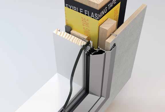
SHADOWCLAD® INSTALLATION - FOR CAVITY CONSTRUCTION
 Table 2: Shadowclad Product Range

                                  Texture                                                             Groove

 Finish                           Natural or Ultra                                                    Natural or Ultra
 Sheet Length                     2440 and 2745mm                                                     2440 and 2745mm
 Width (Overall)                  1216mm                                                              1216mm
 Width (Effective)                1200mm                                                              1200mm
 Cover/Width Tolerance            +/– 1mm                                                             +/– 1mm
 Nominal Thickness                12mm                                                                12mm
 Weight (kg/m2)                   6.6                                                                 6.6
 R-value (m2.C/W)                 0.104                                                               0.104
 Groove Profile                   N/A                                                                 9mm wide, 5mm deep at 150mm centres
 Edge Profile                     Ship lap with weather groove                                        Ship lap with weather groove
 Treatment Available              • H3.1 LOSP (Azole)                                                 • H3.1 LOSP (Azole)
                                  • H3.2 CCA (Ultra finish only)                                      • H3.2 CCA (Ultra finish only)
                                  • Untreated – internal dry applications (Natural finish only)       • Untreated – internal dry applications (Natural finish only)

Shadowclad Exterior Flashing Range                                                  with Shadowclad products and any other building materials or
                                                                                    components of the exterior wall.
Manufactured from extruded aluminium or folded from
0.5mm thick G304 stainless steel, the Shadowclad flashings range                    Aluminium Flashing Finishes
is purpose designed to complement Shadowclad panels used in
                                                                                    Shadowclad aluminium flashings are available in either natural
exterior applications.
                                                                                    anodised finish (silver colour) or in mill finish for powder coating.
Independently tested for weathertightness and compliant
with Table 20 of E2/AS1, Shadowclad flashings achieve 50 year                       Exterior Flashings & H3.2 CCA Treated
durability in all NZS 3604 exposure zones including zone D                          Shadowclad
(sea spray).
                                                                                    Exposure Zone B & C
Note: Stainless steel fasteners should not have contact                             H3.2 CCA treated Shadowclad in exposure zones B and C
with or pierce aluminium flashings. Where stainless                                 (where flashings are exposed to weather) must use mill finished
steel fasteners are to pierce flashings stainless steel                             flashings which must be powder coated to the desired colour or
flashings should be used.                                                           use stainless steel flashings.
The range includes internal and external angles, Horizontal and                     H3.2 CCA treatment contains copper. As such, some form of
inter-storey ‘Z’ flashings and a cavity base closure.                               isolation between aluminium flashings and H3.2 CCA treated
Aluminium horizontally installed flashings come in 3600mm                           panels such as powder coating of the flashings is required. Refer
lengths and vertically installed angles are available in 3000mm                     to Table 21 “Compatibility of Materials in Contact” in E2/AS1 for
and 6000mm lengths - refer Table 4. Stainless Steel flashings are                   more information.
available in 3000mm lengths - refer Table 5.
                                                                                    Exposure Zone D (Sea Spray)
The information, details and performance statements provided
                                                                                    In exposure zone D (sea spray) flashings exposed to weather
in this guide are based on Shadowclad plywood panels and
                                                                                    must be stainless steel for H3.2 CCA treated Shadowclad.
Shadowclad flashings being used together as a system.
CHH Ply does not recommend that Shadowclad plywood panels
                                                                                    H3.2 CCA Treated Shadowclad
be installed with non-CHH Ply flashings. Flashings not supplied by
CHH Ply must, as a minimum, comply with E2/AS1 specifications                       Uncoated aluminium flashings are not permitted to be in direct
and be compatible for use with H3.1 LOSP or H3.2 CCA                                contact in any zone with H3.2 CCA treated Shadowclad under
treated plywood. It is the Designer’s responsibility to ensure that                 any circumstances.
any non-CHH Ply flashings are fit for purpose and compatible

 Table 3: Flashing Durability for Shadowclad

                                                     Exposure Zone
 Sheet Finish                     Treatment                                                       Flashing Material/Finish required
                                                     (refer to section 4 of NZS 3604)

                                                     Zones B and C                                Aluminium Anodised, or Stainless Steel
 Shadowclad Natural/Ultra         H3.1 LOSP
                                                     Zone D (Sea spray)                           Stainless Steel*
                                                     Zones B and C                                Stainless Steel#
 Shadowclad Ultra                 H3.2 CCA
                                                     Zone D (Sea spray)                           Stainless Steel

* Aluminium Powder Coated flashings may be used in Exposure Zone D where they are not pierced by Stainless Steel fasteners. Where stainless steel fasteners are to
pierce flashings stainless steel flashings should be used.
# Aluminium Powder Coated flashings may be used in Exposure Zones B and C where they are not pierced by Stainless Steel fasteners. Where stainless steel
fasteners are to pierce flashings stainless steel flashings should be used.

                                                          CHH PLY | SHADOWCLAD® CAVITY CONSTRUCTION | 0800 326 759 | www.shadowclad.co.nz                                               5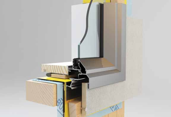
SHADOWCLAD® INSTALLATION - FOR CAVITY CONSTRUCTION
Table 4 Aluminium Shadowclad Flashings Range
Flashing Line Drawing Description Finish Available Length (mm)
Internal 90° Angle
Back flashing for internal Natural Anodised 3000
65 mm
corners or
6000
Internal ‘W’ Angle
60 mm
‘W’ back flashing for Natural Anodised 3000
13 mm
internal corners providing or Mill or
a flush finish with panels 6000
(13mm x 13mm)
Large Internal ‘W’ Angle
‘W’ back flashing for Natural Anodised 3000
internal corners or Mill or
(25mm x 25mm) 6000
60 mm
25 mm
Design Tip: Use a Large
‘W’ where a flush junction
between the Horizontal
‘Z’ flashing and corner
flashing is desired
External Box Angle
60 mm
Box corner for external Natural Anodised 3000
corners providing a flush or Mill or
13 mm
finish with panels 6000
Box corner for external Natural Anodised 3000
Large External Box Angle
corners or Mill or
60 mm
(25mm x 25mm) 6000
Design Tip: Use Large
External Box where a
flush junction between the
Horizontal ‘Z’ flashing and
25 mm
corner flashing is desired
Vertical Top Hat
14 mm
Vertical sheet joint Natural Anodised 3000
flashing or Mill or
6000
134 mm
Cavity Base Closure
Restricts vermin from Natural Anodised 3600
accessing the cavity space
75 mm
16 mm
10 mm
6 CHH PLY | SHADOWCLAD® CAVITY CONSTRUCTION | 0800 326 759 | www.shadowclad.co.nz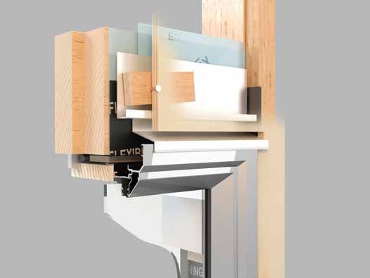
SHADOWCLAD® INSTALLATION - FOR CAVITY CONSTRUCTION
                                 Table 4        Aluminium                                                         Shadowclad Flashings Range

                                 Flashing       Line Drawing                                Description                  Finish Available   Length (mm)

                                                    50 mm
                                                                                            Horizontal ‘Z’ flashing      Natural Anodised     3600
                                                                                            for horizontal joints        or Mill
Horizontal ‘Z’ Flashing

                                                                                            between panels

                                                                    15° Fall

                                                                           35 mm
                                              12.5 mm

                                                                  10

                                                                             5
                                                      50 mm
Inter-Storey ‘Z’ Flashing

                                                                                            Horizontal ‘Z’ flashing      Natural Anodised     3600
                                                                                            for horizontal joints        or Mill
                                                                        15° Fall            between panels when
                                                                                            limiting continuous
                                                                                            cavities to a height of
                                                                                            two storeys or
                                                                                    35 mm

                                                                                            7 metres

                                                                  33 mm
Horizontal ‘Z’ Back Flashing

                                                     50 mm

                                                                                            Back flashing for            Mill                 300
                                                                                            junction of butt jointed
                                                                                            Horizontal ‘Z’ flashing

                                                                       15° Fall
                                                                            35 mm

                                                12.5 mm
Inter-storey ‘Z’ Back Flashing

                                            50 mm

                                                                                            Back flashing for            Mill                 300
                                                                                            junction of butt joint ‘Z’
                                                                                            Flashing inter-storey

                                                                        15° Fall
                                                                                    35 mm

                                                                 32.5 mm

                                                              CHH PLY | SHADOWCLAD® CAVITY CONSTRUCTION | 0800 326 759 | www.shadowclad.co.nz                               7
SHADOWCLAD® INSTALLATION - FOR CAVITY CONSTRUCTION
Table 5 Stainless Steel Shadowclad Flashings Range
Flashing Line Drawing Description Finish Available Length (mm)
3
Back flashing for Stainless Steel 3000
10
internal corners
Internal 90° Angle
65 mm
10
3
65 mm
3 10
'W' back flashing Stainless Steel 3000
for internal corners
Large Internal ‘W’ Angle
(25mm x 25mm)
60 mm
25
10
25
3
60 mm
3
Box corner for Stainless Steel 3000
10
external corners
(25mm x 25mm)
Large External Box Angle
65 mm
65 mm
3
25.9
10
25.4
Restricts vermin Stainless Steel 3000
from accessing the
cavity space
Cavity Base Closure
77 mm
5 mm Dia. holes
at 15 mm centres
13
20
8 CHH PLY | SHADOWCLAD® CAVITY CONSTRUCTION | 0800 326 759 | www.shadowclad.co.nz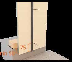
SHADOWCLAD® INSTALLATION - FOR CAVITY CONSTRUCTION
                            Table 5    Stainless Steel                                               Shadowclad Flashings Range

                            Flashing   Line Drawing                                  Description           Finish Available   Length (mm)

                                                                                     Horizontal ‘Z’        Stainless Steel      3000
                                                                                     flashing for

                                         66 mm
                                                                                     horizontal joints
Horizontal ‘Z’ Flashing

                                                                                     between panels

                                                           15° Fall

                                                                 35 mm
                                                    12.5

                                                     10

                                                            7

                                                                                     Horizontal ‘Z’        Stainless Steel      3000
                                                                                     flashing for
                                                                                     horizontal joints
                                         66 mm

                                                                                     between panels
                                                                                     when limiting
Inter-Storey ‘Z’ Flashing

                                                                                     continuous cavities
                                                                                     to a height of two
                                                                                     storeys or
                                                                                     7 metres
                                                                15° Fall
                                                                             35 mm

                                                       33 mm
                                                               10

                                                                         7

                                                 CHH PLY | SHADOWCLAD® CAVITY CONSTRUCTION | 0800 326 759 | www.shadowclad.co.nz                              9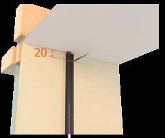
1 . 3 B U I L D I N G M AT E R I A LS F O R U S E W I T H S H A D OWC L A D
SHADOWCLAD® INSTALLATION - FOR CAVITY CONSTRUCTION
(EXTERIOR CLADDING)
Table 6: Materials Available from CHH Ply
Description Treatment Size/Length
Frame Flashing Tape1 For a secure and permanent seal of all Ecoply Barrier openings - 150mm/200mm x 30m
(Use in conjunction with Sill Tape)
Sealing Tape1 For a secure and permanent seal of all Ecoply Barrier vertical joints - 60mm x 30m
Sill Tape1 One piece stretchable sill tape for window and door sills. 2 rolls - 150mm/200mm x 20m
per box
Ecoply® Barrier1 Rigid Air Barrier System H3.2 CCA 2440mm/2745mm x 1200mm
Cavity Batten 45 x 20mm (nominal) H3.1 LOSP Random
Flashings Aluminium and stainless steel flashings range Refer Tables 4 and 5 Refer Tables 4 and 5
1. Please refer to the Ecoply Barrier Specification and Installation Guide for more information.
Building Materials Supplied by Other Manufacturers
• Fasteners (i.e. nails or screws) in accordance with • Window/door head flashings supplied by window
Table 9: Fastener Lengths for Shadowclad fixing. joinery company.
• Building underlay compliant with Table 23 of E2/AS1. • Paint in accordance with paint manufacturer’s
recommendations (refer to 5.3 Coating Selection for
more details).
1 . 4 P R E S E RVAT I V E T R E AT M E N T
Shadowclad is available either H3 treated for use as an exterior use water in the treatment process allowing panels to remain at
cladding or untreated (Natural finish products only) for interior uniform dimensions.
wall and ceiling linings. H3 treated Shadowclad is treated in
When coating H3.1 LOSP treated plywood some residual
accordance with AS/NZS 1604.3 with the standard treatment
solvent may be present on the sheet surface from the treatment
for Shadowclad panels being H3.1 LOSP (Azole). H3.2 CCA
process. Sheets feeling greasy to touch should be placed in a
treatment is available for Shadowclad Ultra panels if required.
well ventilated area and allowed to flash off to ensure proper
Shadowclad is envelope preservative treated. Where adhesion of paints and stains to the sheet surface.
sheets are cut, cuts must be coated with a brush on
Mechanical fasteners are required to fix H3.1 LOSP treated
timber preservative in accordance with the relevant
Shadowclad to framing. Do not glue Shadowclad to frames.
manufacturer’s instructions. Soudal® Metalex®
Concentrated Timber Preservative Clear (Soudal®
H3.2 CCA Treatment
Metalex® Clear) is recommended. Failure to properly
apply preservative to cut edges will negatively affect H3.2 CCA uses water during the treatment process and may
the durability of the cut panels. leave panel surfaces with a slight green colour. For this reason
H3.2 CCA treatment is available only in the Shadowclad Ultra
H3.1 LOSP Treatment
finish.
H3.1 LOSP treatment is the standard treatment for Shadowclad
panels as it does not discolour the panel surface and does not
Table 7: Preservative Treatment Options
Untreated H3.1 LOSP (Azole) H3.2 CCA
Preservative Carrier N/A Light organic oil (white spirits) Water
Colour Natural Natural Green
Fungicide Heat treated dry wood Propiconazole and Tebuconazole Copper
Insecticide Heat treated dry wood Permethrin Arsenate
Other Chemicals N/A Butyl Oxitol Chrome
(co-solvent to assist active stability) (to fix preservative in water)
Mouldicide N/A IPBC Copper (limited efficiency)
Notes Plywood for dry interior use, supplied Solvent does not affect dimensions. Dried after treatment to average
ex mill at1 . 5 S U S TA I N A B I L I T Y
SHADOWCLAD® INSTALLATION - FOR CAVITY CONSTRUCTION
Shadowclad is manufactured from radiata pine. It is grown on Shadowclad is manufactured in New Zealand at
tree farms which are tended and harvested to provide wood CHH Ply Tokoroa plywood mill.
for plywood manufacture. The crop is managed on a sustainable
Shadowclad is available Forestry Stewardship Council (FSC)
basis to yield millable trees. New Zealand plantations are
(FSC-C012019) certified upon request.
managed in compliance with the New Zealand Forest Accord.
1 . 6 P RO D U C T I D E N T I F I C AT I O N
In accordance with AS/NZS 2269, every sheet of Shadowclad Treated Example
plywood has the following information marked on the back:
S H A D OWC L A D ® S T RU C T U R A L A
• Brand name: e.g. SHADOWCLAD®. BOND E0 AS/NZS 2269.0:2012
A S / N Z S 1 6 0 4 . 3 : 2 0 1 2 4 0 0 6 4 H 3 E LO S P
• Intended application: e.g. STRUCTURAL.
R E T R E AT C U T S PAT 0 1 / 1 2 / 1 5 1 2 : 2 3 : 4 5
911
• Glue bond: e.g.. A BOND.
• Formaldehyde emission class: e.g. E0.
• Australasian Standard: e.g. AS/NZS 2269:2012.
• Treatment Standard (if applicable) e.g. AS/NZS 1604.3:2012.
• Date and time of manufacture: e.g. 01/12/15 12:34:56.
• The Engineered Wood Products Association of Australasia
(EWPAA) brand and mill number: e.g. 911 (Tokoroa mill).
2.0 DESIGN CONSIDERATIONS
2.1 DESIGN RESPONSIBILITY
Design responsibility lies with the building owner and the Good detailing which avoids moisture or dust accumulation on
professionals that they engage. The specifier for the project must the sheet surface can help increase durability and aesthetics. Roof
ensure that the details in the specification for their individual overhangs contribute to performance as they offer shade and
projects are appropriate for the intended application. The will protect walls from rain and dust. Trims should be bevelled to
specifier must also ensure that additional detailing is provided shed moisture and flashings should be detailed with gaps that do
for specific design or any areas that fall outside the scope and not trap water at the panel edges.
specifications of this literature. It is the specifier’s responsibility
to ensure that non-CHH Ply products are fit for purpose, and
compatible with Shadowclad products.
2 . 2 L I T E R AT U R E S CO P E
Shadowclad can be used for those structures which fall within timber frame and building underlay.
the scope of Acceptable Solution E2/AS1- External Moisture.
Shadowclad is not recommended where a risk score >20 in
Shadowclad is recommended for a drained and ventilated cavity,
accordance with E2/AS1 is established.
where the cladding is fixed onto timber battens fixed over the
2 . 3 CO D E CO M P L I A N C E
Shadowclad on a cavity wall system is tested in accordance with E2/VM1 and AS/NZS 4284 “Testing of Building Facades” for
compliance with the NZBC Clause E2 - External Moisture.
2 . 4 S I T E & F O U N DAT I O N S
The site on which the building is situated must comply with the Acceptable Solution E1/AS1 of the Approved Document for the NZBC
Clause E1 - Surface Water.
CHH PLY | SHADOWCLAD® CAVITY CONSTRUCTION | 0800 326 759 | www.shadowclad.co.nz 112 . 5 G RO U N D C L E A R A N C E S
SHADOWCLAD® INSTALLATION - FOR CAVITY CONSTRUCTION
The bottom edge of each Shadowclad sheet must be a minimum For garage door openings, refer Paragraph 9 “Openings to
of 50mm above decks and verandahs, 100mm above paved garages” in Acceptable Solution E2/AS1.
ground and a minimum of 175mm above unprotected ground.
Shadowclad must overhang the bottom plate on a concrete
slab by a minimum of 50mm as required by NZS 3604 and E2 -
External Moisture. Maximum distance from the bottom of the
sheet to the fixing shall not exceed 75mm.
2 . 6 M O I S T U R E M A N AG E M E N T
It is the responsibility of the specifier to identify moisture Where a deck is attached to the building and the Shadowclad
related risks associated with any particular building design and extends below the deck to cover the framing, keep decking clear of
site exposure. the Shadowclad surface and detail to avoid moisture entrapment.
Wall construction design must effectively manage moisture, All wall openings, penetrations, junctions, connections, window
accounting for both the interior and exterior environments sills, heads and jambs must incorporate Shadowclad flashings
of the building. This is particularly important in buildings that for waterproofing. Materials, components and the installation
have a higher risk of wind driven rain penetration or that are used to manage moisture in framed wall construction must, at a
artificially heated or cooled. minimum, comply with the requirements of the NZBC.
2 . 7 W I N D LOA D I N G
Shadowclad is suitable for use in all wind zones up to and design wind pressures up to design differential ultimate limit state
including extra high (55m/s) as defined by NZS 3604 and specific (ULS) of 2.5kPa.
2.8 DURABILITY
The durability level applicable to Shadowclad is dependent upon should expect an increased level of coating maintenance over
the application and coating applied. Detailing, treatment and the life of the cladding than would normally be expected where
installation methods need careful consideration to satisfy the lighter colours are used.
requirements of the NZBC.
Using dark colours with an LRV of less than 50% and
failure to adequately maintain the surface coating of the
Exterior Cladding – 15 Year Durability
cladding increases the risk of aesthetic related issues
CHH Ply does not recommend Shadowclad is left such as face checking. For this reason, CHH Ply does not
uncoated when used as an exterior cladding. support the use of dark colours on Shadowclad exterior
cladding.
The NZBC Clause B2 requires claddings to achieve a minimum
structural durability level of 15 years. Additional Notes:
For further advice on coatings refer to section 5.0: Coating and
Shadowclad coated with stains or paints (regardless of colour
Application – Exterior Cladding.
choice) will meet this requirement. However, if using dark
colours (colours with an LRV of less than 50%) homeowners
2 . 9 T E X T U R E D V S . S M O OT H F I N I S H E D P LY WO O D A S E X T E R I O R C L A D D I N G
Structurally, some smooth faced plywood products may meet the Shadowclad features a textured (bandsawn) face which reduces
requirements of E2/AS1 however in CHH Ply opinion smooth the visibility of natural face checking which can occur in any
faced plywood does not retain a high visual appearance when wood based product which has been exposed to weather for a
directly exposed to weathering. prolonged period.
Where a high visual appearance is desired (such as exterior Face checks are not considered a manufacturing fault as they are
cladding) CHH Ply recommends the use of Shadowclad rather part of a natural process and are merely an indication that it is
than smooth faced plywood. time to re-apply the surface coating on the product.
12 CHH PLY | SHADOWCLAD® CAVITY CONSTRUCTION | 0800 326 759 | www.shadowclad.co.nz2 . 1 0 H E A LT H & S A F E T Y
SHADOWCLAD® INSTALLATION - FOR CAVITY CONSTRUCTION
Shadowclad should be installed and used as per the (sawing, routing, planing, drilling etc.) a class P1 or P2 replaceable
Safety Data Sheet (SDS) which can be downloaded from filter or disposable face piece respirator should be worn.
www.shadowclad.co.nz.
Wear comfortable work gloves to avoid skin irritation and the
Always wear safety glasses or non-fogging goggles when cutting risk of splinters. Wash hands with mild soap and water after
Shadowclad panels and flashings. handling panels.
If wood dust exposures are not controlled when machining
2 . 1 1 S TO R AG E & H A N D L I N G
Shadowclad Panels: Shadowclad Flashings:
• Keep Shadowclad panels dry.
®
• Keep dry. Should a shipment of Shadowclad flashings
• Store under cover. arrive in a wet condition, they should be immediately dried
• Handle and stack with care to avoid damage. before storing.
• Stack flat; clear of ground, on at least three evenly spaced • When storing flashings avoid contact with other metals which
bearers. may cause scratches or marks. The use of shelving or racks
• Store in well-ventilated areas away from sources of heat, flames faced with dry wood is recommended.
or sparks. • Keep away from caustics, nitrates and acids.
3.0 INTERIOR LININGS
The use of untreated plywood is acceptable under NZS 3604, For detailed installation advice for plywood used as an internal
NZBC for internal wall and ceiling linings where NZS 3602 lining refer to www.chhply.co.nz.
allows the use of untreated plywood.
CHH PLY | SHADOWCLAD® CAVITY CONSTRUCTION | 0800 326 759 | www.shadowclad.co.nz 134.0 INSTALLATION – EXTERIOR CLADDING
SHADOWCLAD® INSTALLATION - FOR CAVITY CONSTRUCTION
4.1 FRAMING – DURABILITY
Refer to NZBC Acceptable Solution B2/AS1 “Durability”. refer to NZS 3602 as well as framing manufacturer’s literature
External timber framing must be treated to a minimum H1.2 (e.g. Laserframe®). The current Laserframe Product Guide can
treatment. For timber treatment and allowable moisture content, be downloaded from www.chhwoodproducts.co.nz.
4 . 2 F R A M I N G – CO N S T RU C T I O N
Use kiln dried framing such as Laserframe in accordance with All Shadowclad sheet edges must be fully supported by framing.
timber framing manufacturer’s specifications and treated in
• Studs must not exceed 600mm centres.
accordance with NZS 3602. The current Laserframe Product
• Nogs must be provided at a maximum of 800mm centres.
Guide can be downloaded from www.chhwoodproducts.co.nz.
- When using vertical cover battens nogs at maximum
Timber frame sizes and set out must comply with NZS 3604 600 centres.
(or specifically designed to NZS 3603) and with stud and nog • An extra stud is required at internal corners for
centres and timber width required by this specification. ventilated cavities.
• Refer to NZS 3602 for moisture content requirements as a
guide, frame and cavity batten moisture content should be no
greater than 20%.
• Framing must be kept as dry as possible at all times.
• Single spans of Shadowclad should not exceed 600mm
(e.g. below windows or balustrades).
4 . 3 P R E PA R AT I O N – B U I L D I N G U N D E R L AY & R I G I D A I R BA R R I E R
The use of building underlay compliant with Table 23 of E2/AS1 • Rigid air barriers are also required in high wind zones and
or an alternative solution rigid air barrier must be provided over above for Ministry of Education school properties.
framing prior to the installation of exterior cladding.
For more information on rigid air barriers refer to the current
• Barriers to air flow are required.
Ecoply Barrier Specification and Installation Guide which can be
• Rigid air barriers are required in extra high wind zones
downloaded from www.ecoplybarrier.co.nz.
and above.
4 . 4 P R E PA R AT I O N – C AV I T Y CO N S T RU C T I O N
Cavity Construction attens must be fixed over the building underlay/rigid air barrier
B
to all studs, as follows.
A Shadowclad cavity base closure must be installed at the
bottom of all walls and above window heads, this provides If studs are at 600mm centres:
vermin proofing to ventilation openings. The holes in the cavity • Battens must be fixed vertically at 300mm centres
base closure must be kept clear to enable ongoing drainage and (i.e. a batten on studs and one in between the two studs fixed
ventilation of the cavity. to top and bottom plates and nogs).
• Battens fixed to studs are to support Shadowclad and restrain
Cavity Battens building underlay and insulation from bulging into the cavity.
• The Shadowclad must not be fixed to these cavity battens
Cavity battens provide an air space between the frame and
where there is no framing behind them.
the sheet and are considered a “packer” when installed in
accordance with Acceptable Solution E2/AS1. If studs are at 400mm centres battens may be fixed on
studs only.
The battens must be fixed over the building underlay or a rigid
air barrier. orizontal battens must be used at the top of the wall to block
H
the top of the cavity from venting into the roof space.
All timber battens must: be nominal 20mm thick (between limits
of 18mm and 25mm in thickness); at least the same width as the
Cavity spacers (i.e. short pieces of cavity batten) may be used
stud; and minimum H3.1 LOSP treated in accordance with to support the bottom sheet edge (or provide intermediate
NZS 3640. support where required e.g. above window openings) but must
allow water drainage to the outside. The cavity spacers must be
Polystyrene battens must not be used with H3.1 LOSP treated
fixed at a 5˚ minimum slope with a 50mm minimum air gap at
Shadowclad panels, as they may melt in contact with solvents.
either side.
14 CHH PLY | SHADOWCLAD® CAVITY CONSTRUCTION | 0800 326 759 | www.shadowclad.co.nzSHADOWCLAD® INSTALLATION - FOR CAVITY CONSTRUCTION
SC001: Typical Framing Setout (without Battens) Studs at 600 Centres
600 600 600 600 1200
Sheet joint Sheet joint Sheet joint Sheet joint
800
Soffit line
Maximum nog spacing2
Window Door
800 800
Batten fixing - 40 x 2.5 mm flat head
nails at maximum 800 mm centres
Internal corner
Note:
1. Single spans of Shadowclad® must not exceed 600 mm (e.g. below windows or on balustrades)
2. When using vertical cover battens, nogs at maximum 600 centres
SC001A: Typical Framing Setout (without Battens) Studs at 400 Centres
Framing Centres
400 400 400 400 400 400 1200
Sheet joint Sheet joint Sheet joint Sheet joint
800
Maximum nog spacing2
Soffit line
Window Door
800 800
Internal corner
Note:
1. Single spans of Shadowclad must not exceed 600 mm (e.g. below windows or on balustrades)
2. When using vertical cover battens, nogs at maximum 600 centres
CHH PLY | SHADOWCLAD® CAVITY CONSTRUCTION | 0800 326 759 | www.shadowclad.co.nz 15SHADOWCLAD® INSTALLATION - FOR CAVITY CONSTRUCTION
SC002: Typical Framing Setout (with Battens) Studs at 600 Centres
Framing Centres
600 600 600 600 1200
Sheet joint Sheet joint Sheet joint Sheet joint
800
Soffit line
Maximum nog spacing1
Window Door
800
800
Batten fixing - 40 x 2.5 mm flat head
nails at maximum 800 mm centres
Internal corner
Note:
1. When using vertical cover battens nogs at maximum 600 centres
SC002A: Typical Framing Setout (with Battens) Studs at 400 Centres
Framing Centres
400 400 400 400 400 400 1200
Sheet joint Sheet joint Sheet joint Sheet joint
800
Soffit line
Maximum nog spacing1
Window Door
800
800
Batten fixing - 40 x 2.5 mm flat head
nails at maximum 800 mm centres
Internal corner
Note:
1. When using vertical cover battens nogs at maximum 600 centres
16 CHH PLY | SHADOWCLAD® CAVITY CONSTRUCTION | 0800 326 759 | www.shadowclad.co.nz4 . 5 S H E E T L AYO U T
SHADOWCLAD® INSTALLATION - FOR CAVITY CONSTRUCTION
A sheet layout should form part of architectural drawings and be • All treated Shadowclad panels are envelope preservative
used from the basis of stud/framing layout. treated. Where sheets are cut, edges must be coated
with a brush on timber preservative such as
• Sheet edges must be supported by the framing.
Soudal® Metalex® Clear.
• Sheets are designed to be vertically fixed. Do not fix sheets
• Cut edges must be placed at the top of the sheet to avoid rain
horizontally.
drips soaking in to cut end grains.
• When laying up on to framing, start at framing corners and
• Priming the bottom edges and the back (rear) of the sheets to
work across the wall.
a height of 150mm is required.
- Shadowclad Ultra sheets are coated on the rear to a height
of 150mm (minimum) to meet this requirement.
4 . 6 F I X I N G S – FA S T E N E R D U R A B I L I T Y
Table 8: Fastener Durability for Shadowclad
Finish Treatment Exposure Zone (Refer to Section 4 of NZS 3604) Material Required
Shadowclad Natural/Ultra H3.1 LOSP Zones B and C Minimum hot dipped galvanised or better
Zone D (sea spray) Stainless Steel
Shadowclad Ultra H3.2 CCA All Zones Stainless Steel
4 . 7 F I X I N G S – FA S T E N E R S I Z E & L AYO U T
Table 9: Fastener Lengths for Shadowclad
Minimum Fastener Length and Size (Cavity Fix)
Nails in Timber 60 x 2.8mm
Screws in Timber 8g x 65mm
Shadowclad must be nailed or screwed to timber as per below: Power Driven Fastening
• Use flat head (full round head) nails or rose head nails with • Best practice is to hand drive nails as better control of nail
timber framing. Rose head nails should be considered where a depth is achieved.
more decorative fastener is desired. • Paslode Impulse Nailers may be used to fire power driven nails.
• Standard fixing pattern: fasten sheet edges at 150mm centres Refer to Paslode for suitable fasteners as per the minimum
and within the panel on all supports at 300mm centres. lengths stated in Table 9.
• Do not fix to battens that are not installed over studs as the • Do not overdrive nails into the sheet.
nails will puncture the building wrap.
Fixings at Vertical Sheet Join
• Fasten no closer than 7mm to sheet edges except on edge with
top lap (weather groove lap), do not nail through top lap. Shadowclad Sheets must be fastened off independently to each
• Fasten Ship lap joints independently to ensure natural sheet other. SC006A and SC008A show specific fastener locations to
expansion is not restricted. accommodate the Ship lap joint. For Shadowclad Texture and
• When using a rigid air barrier the Shadowclad fastener lengths Shadowclad Groove respectively fasten underlap 13mm from
should be increased by the thickness of the panel to ensure sheet edge, with overlap fasten 23mm from sheet edge as detailed.
required fastener pull out loadings are achieved.
• Drive nails and screws flush.
• Do not nail through the grooves in Shadowclad Groove panels.
CHH PLY | SHADOWCLAD® CAVITY CONSTRUCTION | 0800 326 759 | www.shadowclad.co.nz 17SHADOWCLAD® INSTALLATION - FOR CAVITY CONSTRUCTION
SC003: Shadowclad Fastener Layout (Studs at 600 Centres Shown)
Framing centres
600 600 600 600
Nails at 300 mm
centres to
800
intermediate
studs and nogs
Maximum nog spacing1
Nails at
150 mm
centres to
800
sheet
perimeter
800
50 mm minimum sheet overhang
(refer SC042, SC044 & SC046 as appropriate)
Note:
1. When using vertical cover battens nogs at maximum 600 centres
4 . 8 I N S TA L L AT I O N TO O LS F O R S H A D OWC L A D ®
Correct installation and maintenance of Shadowclad® is necessary access to all current literature, installation details, maintenance and
to ensure that compliance with the New Zealand Building Code, other key installation requirements.
durability, structural integrity and weathertightness are maintained.
CHH Ply have developed two installation tools to compliment the Shadowclad Stick
Shadowclad Specification and Installation Guides. These products
The Shadowclad Stick is an installation tool for Shadowclad. This
are an extension of the Specification and Installation Guides and
tool removes the need for builders to develop their own ‘jigs’
are available by contacting CHH Ply directly via www.shadowclad.
to aid in ensuring that critical clearances, nail spacing’s, etc. are
co.nz or by calling 0800 326 759.
applied during the installation of Shadowclad sheets. Section 11
of this literature provides information in relation to the use of the
Shadowclad stick.
Shadowclad® sITe APP
The Shadowclad sITe APP is a tool for all building practitioners to
aid in the installation of Shadowclad in accordance with the
CHH Ply Specification and Installation Guides. The APP includes a
context sensitive Key Design Points and Installation Checklist,
18 CHH PLY | SHADOWCLAD® CAVITY CONSTRUCTION | 0800 326 759 | www.shadowclad.co.nz4 . 9 S H A D OWC L A D K E Y I N S TA L L AT I O N & D E S I G N P O I N T S
SHADOWCLAD® INSTALLATION - FOR CAVITY CONSTRUCTION
The following tasks are provided to installers to point out key installation and design factors when used as an exterior cladding.
These do no detract from the requirements to read and understand this literature as a whole.
Task Tick when checked
Prior to Specification and Installation
Read the Shadowclad Specification and Installation Guide in its entirety
Framing Plan
Framing setout drawings to suit Shadowclad fixing and installation guidelines
Sheet Cuts
Coat all sheet cuts with a preservative timber treatment such as Soudal® Metalex® Clear
After applying Soudal® Metalex® Clear, apply the surface coating (e.g. paint or stain) to cut edges
Place uncut edge to bottom
Fastener Material Type
Galvanised fasteners or better used (Stainless steel annular groove nails required in sea spray zones and with
H3.2 CCA treated Shadowclad Ultra)
Sheet Fastener Pattern
Around sheet edge – maximum 150mm centre spacing
Within sheet body – maximum 300mm centre spacing
Horizontal Sheet Joints
Minimum 9mm separation gap between sheets above all Horizontal ‘Z’ flashings
Prime the bottom of the sheet edge and 150mm up the back (rear) of the sheets
50mm strip of neutral cure silicon sealant or stop ends at all ‘Z’ flashing terminations excluding terminations at Shadowclad
metal corner flashings
Back flashings or 150mm overlap to all flashing butt joints
Expansion Gaps Between Sheets (Vertical Sheet Joints)
Texture Profile Sheets - 2mm gap between vertical edges of sheets
Groove Profile Sheets - 9mm gap (i.e. full groove space) between vertical edges of sheets
Note: Expansion gaps required between vertical edges of sheets to accommodate natural expansion and contraction of sheets
Ground Clearances
Paved/Sealed Ground - minimum 100mm distance from the ground to sheet bottom
Broken Ground - minimum 175mm distance from the ground to sheet bottom
Prime the bottom of the sheet 150mm up the back (rear) of the sheet
Refer to the current Shadowclad® Specification and Installation Guide for full installation specifications and suggested details.
CHH PLY | SHADOWCLAD® CAVITY CONSTRUCTION | 0800 326 759 | www.shadowclad.co.nz 194 . 1 0 V E RT I C A L S H E E T J O I N T S
SHADOWCLAD® INSTALLATION - FOR CAVITY CONSTRUCTION
Shadowclad sheets have a built-in Ship lap joint and weather Shadowclad is envelope preservative treated. Where
groove on the long edges of all sheets. sheets are cut, ends must be coated with a brush on
timber preservative in accordance with the relevant
When installing Shadowclad Groove profile sheets, use a 9mm
manufacturer's instructions. Soudal® Metalex® Clear is
temporary spacer in the groove alongside Ship lap joint to
recommended. Failure to properly apply preservative
establish correct expansion gap.
to cut edges will negatively affect the durability of cut
panels.
SC004: Shadowclad Texture and Groove Sheet Dimensions
18
5.5
12
1195 21
Texture Profile
16 9
12
5.5
1195 21
Groove Profile
SC006: Shadowclad Texture Vertical Joint (Cavity)
45
Stud
Building underlay
Cavity batten
Sheets to be fastened off
Note: independently of each other
1. Do not nail through weather groove
2. Refer to SC006A for specific nail locations 2 mm expansion gap
20 CHH PLY | SHADOWCLAD® CAVITY CONSTRUCTION | 0800 326 759 | www.shadowclad.co.nzSHADOWCLAD® INSTALLATION - FOR CAVITY CONSTRUCTION
SC006A: Shadowclad Texture Vertical Joint Fastener Locations (Cavity)
13 23
SC008: Shadowclad Groove Vertical Joint (Cavity)
45
Stud
Building underlay
Cavity batten
Sheets to be fastened off
independently of each other
Note:
1. Do not nail through Fix clear of weather groove
9
weather groove
Use temporary 9 mm spacer
2. Refer to SC008A for
specific nail locations 9 mm gap at exterior face of sheets
for Shadowclad® Groove profile only
SC008A: Shadowclad Groove Vertical Joint Fastener Locations (Cavity)
13 23
CHH PLY | SHADOWCLAD® CAVITY CONSTRUCTION | 0800 326 759 | www.shadowclad.co.nz 21SHADOWCLAD® INSTALLATION - FOR CAVITY CONSTRUCTION
SC010: Shadowclad Vertical Joint with Optional Cover Batten (Cavity)
45
Stud
Building underlay
Cavity batten
Sheets to be fastened off
independently of each other
H3 treated 65 x 18 mm minimum timber
Note: batten with 6 x 6 weather grooves
1. Do not nail through weather groove 2 mm expansion gap
SC012: Shadowclad Nogging for Vertical Cover Batten Between Studs (Cavity)
Interior wall lining
Stud
Nogging between studs at maximum
600 centres for fixing
50 mm Building underlay
min.
100 mm maximum long cavity spacer
5° minimum slope (1:12)
65 x 18 mm minimum timber batten with
6 x 6 mm weather grooves
Plan Cavity batten
Shadowclad®
Interior lining
Nogging between studs at maximum
600 centres
100 mm maximum long cavity spacer
5° minimum slope (1:12)
65 x 18 mm minimum timber batten with
6 x 6 mm weather grooves
Shadowclad
Vertical section
22 CHH PLY | SHADOWCLAD® CAVITY CONSTRUCTION | 0800 326 759 | www.shadowclad.co.nzSHADOWCLAD® INSTALLATION - FOR CAVITY CONSTRUCTION
SC014: Shadowclad Vertical Joint with Top Hat Flashing (Cavity)
45 45
Stud
Building underlay
Cavity batten
2 2
50 mm min. 2 mm expansion gap
Vertical box flashing
Note:
1. Treat all cut edges with Soudal® Metalex® Clear
4 . 1 1 H O R I ZO N TA L S H E E T J O I N T S
At floor joist level a horizontal joint must be provided to If aluminium ‘Z’ flashings are being used, all butt joints must
accommodate the movement resulting from timber joist include proprietary back flashings. Stainless steel flashings should
shrinkage and settlement. be lapped by a minimum 150mm at joins.
A Shadowclad Horizontal ‘Z’ flashing should be used for A 50mm strip of neutral cure silicon (refer to SC0100 General
horizontal sheet joints. Silicon Sealing of Horizontal ‘Z’ Flashings) or stop ends (as
applicable) required at all ‘Z’ flashing terminations excluding
Acceptable Solution E2/AS1 requires drained cavities to be
terminations at Shadowclad metal corner flashings.
limited to a height of two storeys.
CHH PLY | SHADOWCLAD® CAVITY CONSTRUCTION | 0800 326 759 | www.shadowclad.co.nz 23SHADOWCLAD® INSTALLATION - FOR CAVITY CONSTRUCTION
SC0100: Shadowclad General Silicon Sealing of Horizontal ‘Z’ Flashings
Wall framing
Building underlay
Shadowclad® 90° internal corner flashing
Cavity batten
50 mm
min.
Neutral cure silicon sealant gunned into
gap between ‘Z’ flashing, Shadowclad and
corner board
Timber cover board
Sloping packer with building underlay
Shadowclad Horizontal ‘Z’ flashing
Shadowclad
SC016: Shadowclad Mid Floor Horizontal Joint (Cavity)
Shadowclad
Building underlay
Cavity spacers with 50 mm minimum
air gap on both sides. 5° minimum
slope (1:12). Position to allow
Shadowclad fixing at 150 mm centres Notes:
1. 50 mm strip of neutral cure silicon
Treat all Shadowclad cut edges with sealant must be provided at the
Soudal® Metalex® Clear termination point of all ‘Z’ flashings
9
Expansion control joint at windows, corner boxes, etc
(refer to SC0100)
15° Cross slope of Flashing
2. Detail is only suitable for drained
Shadowclad Horizontal ‘Z’ flashing cavities up to two storeys or 7 m in
height. For drained cavities over
two storeys or 7 m in height refer
Internal wall lining to detail SC018 Horizontal Joint -
Non Continuous (Cavity)
3. Back flashings or 150 mm overlap
required at all horizontal flashing
butt joints (refer to SC0102 and
SC0104)
Vertical section
4. Treat all Shadowclad cut edges
with Soudal® Metalex® Clear
24 CHH PLY | SHADOWCLAD® CAVITY CONSTRUCTION | 0800 326 759 | www.shadowclad.co.nzSHADOWCLAD® INSTALLATION - FOR CAVITY CONSTRUCTION
SC018: Shadowclad Mid Floor Horizontal Joint – Non Continuous (Cavity)
Shadowclad®
Building underlay
Cavity spacers with 50 mm minimum air gap on both sides. 5° minimum slope
(1:12). Position to allow Shadowclad fixing at 150 mm centres
Additional building underlay from
overlap above lapped over flashing
Notes:
75 mm minimum upstand cavity base 1. Stop ends must be provided at
closure vent strip. Position to give 15 mm
drip edge to cladding the termination point of all
inter-storey ‘Z’ flashings
9
Expansion control joint 2. Detail SC016 Mid Floor
Horizontal Joint (Cavity) may
Shadowclad inter-storey be used for continuous cavity
Horizontal ‘Z’ head flashing with up to two storey or 7 m in
15° cross slope height
3. Back flashings or 150 mm
Internal wall lining overlap required at all
horizontal flashing butt joints
(refer to SC0102 and SC0104)
4. Treat all Shadowclad cut edges
Vertical section with Soudal® Metalex® Clear
4 . 1 2 E X T E R N A L CO R N E R S
SC020: Shadowclad External Corner with External Box Flashing (Cavity)
Shadowclad
Interior lining
Building underlay continuous around corner
2 mm
Shadowclad exterior box corner flashing
Plan 2 mm expansion gap
Sizes available:
Small box: 13 mm x 13 mm
Large box: 25 mm x 25 mm
Note:
1. Treat all cut edges with Soudal® Metalex® Clear
CHH PLY | SHADOWCLAD® CAVITY CONSTRUCTION | 0800 326 759 | www.shadowclad.co.nz 25SHADOWCLAD® INSTALLATION - FOR CAVITY CONSTRUCTION
SC022: Shadowclad External Corner with Cover Boards (Cavity)
Shadowclad®
Interior lining
Building underlay continuous around corner
Shadowclad 90° internal corner flashing
Plan Ex. 25 mm minimum timber cover boards with 6 x 6 mm
65 mm weathergrooves. Set cladding edge back 8 mm to
min. cover
create drainage cavity
Note:
1. Treat all cut edges with Soudal® Metalex® Clear
2. 50 mm strip of sealant must be provided at the
termination point of all ‘Z’ flashings at windows,
corner boxes, etc. (refer to SC0100)
4 . 1 3 I N T E R N A L CO R N E R S
SC024: Shadowclad Internal Corner with 90˚ Flashing (Cavity)
Shadowclad
Interior lining
Building underlay continuous around corner
Shadowclad 90° internal corner flashing
2 mm expansion gap
Plan Note:
1. Treat all cut edges with Soudal® Metalex® Clear
26 CHH PLY | SHADOWCLAD® CAVITY CONSTRUCTION | 0800 326 759 | www.shadowclad.co.nzSHADOWCLAD® INSTALLATION - FOR CAVITY CONSTRUCTION
SC026: Shadowclad Internal Corner with ‘W’ Flashing (Cavity)
Shadowclad®
Interior lining
Building underlay continuous around corner
Nail fixing to be clear of flashing
2 mm expansion gap
Shadowclad internal 'W' corner flashing
Sizes available:
Plan Small 'W': 13 mm x 13 mm
Large 'W': 25 mm x 25 mm
Note:
1. Treat all cut edges with Soudal® Metalex® Clear
4 . 1 4 S H A D OWC L A D F L A S H I N G J U N C T I O N P O I N T S
Flashings should have expansion joints where necessary to provide Internal and External Flashings
adequate allowance for thermal expansion as set out below.
Internal and external angles and ‘Z’ flashings can be nominally
• Expansion joints to be provided for joined flashings when their fixed with hot dipped galvanised or stainless steel (as applicable)
combined length exceeds 8 metres. flat head nails and then permanently fixed with the Shadowclad
• Even if less than 8 metres in length, where both ends of a fasteners penetrating the flashing wings/upstands.
flashing are constrained and fixed, allowance should be made
for expansion. Horizontal ‘Z’ Flashings
Horizontal aluminium ‘Z’ flashings should be butted together with
Cavity Base Closure a back flashing to create a weathertight joint (refer to SC0102).
Fix Shadowclad cavity base closures to bottom plates through the Stainless steel back flashings should overlap by a minimum of
upstand with 40 x 2.5mm, hot dipped galvanised or stainless steel 150mm at joins to create weathertight joints where horizontal
(as appropriate) flat head nails at 300mm centres. flashings meet (refer to SC0104).
The cavity base closure should be positioned to allow a minimum
‘Z’ Flashings Terminations
drip edge to the wall cladding of 15mm at the base of walls, and
15mm above window head flashings. Where inter-storey ‘Z’ flashings terminate stop ends must
be installed.
A 50mm strip of neutral cure silicon (refer to SC0100 General
Silicon Sealing of Horizontal ‘Z’ Flashings) or stop ends (as
applicable) required at all ‘Z’ flashing terminations excluding
terminations at Shadowclad metal corner flashings.
CHH PLY | SHADOWCLAD® CAVITY CONSTRUCTION | 0800 326 759 | www.shadowclad.co.nz 27SHADOWCLAD® INSTALLATION - FOR CAVITY CONSTRUCTION
SC0102: Shadowclad Aluminium Flashing Junctions and Connections (Cavity)
SC0104: Shadowclad Stainless Steel ‘Z’ Flashing Joins (Cavity)
28 CHH PLY | SHADOWCLAD® CAVITY CONSTRUCTION | 0800 326 759 | www.shadowclad.co.nz4 . 1 5 W I N D OW P E N E T R AT I O N S
SHADOWCLAD® INSTALLATION - FOR CAVITY CONSTRUCTION
Window joinery flashings (i.e. head and sill flashings) should be as the Window Association of New Zealand Window Installation
sourced from the joinery fabricator to meet the requirements of System (WANZ WIS) which can be downloaded
Acceptable Solution E2/ASI or an Alternative Solution such at www.wanz.org.nz.
SC028: Shadowclad Window Head Detail (Cavity)
Shadowclad®
Building underlay
Cavity battens
Lintel
Flexible flashing tape strip placed over
building underlay and flashing joint
Cavity spacers with 50 mm minimum air gap on both
sides. 5° minimum slope (1:12). Position to
9 50 mm
cover
allow Shadowclad fixing at 150 mm centres
75 mm minimum upstand cavity base closure vent
strip. Position to give 15 mm drip edge to cladding
7.5 mm
10 mm
cover
Head flashing with 15° slope. 15 mm
high stop ends within cavity
Sealant between head flashing and window flange
in very high wind zone and above
Interior jamb liner over timber packer
Fit air seal over PEF
Note:
1. Treat all cut edges with Soudal® Metalex® Clear
2. Stop ends to head flashing terminations
CHH PLY | SHADOWCLAD® CAVITY CONSTRUCTION | 0800 326 759 | www.shadowclad.co.nz 29You can also read