Design for deconstruction and reuse of timber structures - state of the art review
←
→
Page content transcription
If your browser does not render page correctly, please read the page content below
Design for deconstruction and reuse of timber
structures – state of the art review

Carmen Cristescu, Daniel Honfi, Karin Sandberg, Ylva Sandin,
Elizabeth Shotton, St John Walsh, Marlene Cramer, Daniel Ridley-
E l l i s , M i c h a e l R i s s e , R a p h a e l a I v a n i c a , A n n e t e H a r t e , C a i t r í o n a Uí
Chúláin, Marina De Arana-Fernández, Daniel F. Llana, Guillermo
Íñiguez-González, Manuel García Barbero, Bahareh Nasiri, Mark
Hughes, Žiga Krofl

InFutUReWood Report:1

RISE Report 2020:05

ISBN: 978-91-89167-67-4

DOI: 10.23699/bh1w-zn97
Design for deconstruction and reuse of timber
structures – state of the art review

C. CRISTESCU1, D. HONFI1, K. SANDBERG1, Y. SANDIN1, E. SHOTTON2, S. WALSH2,
M. CRAMER3, D. RIDLEY-ELLIS3, M. RISSE4, R. IVANICA4, C. UÍ CHÚLÁIN5, A.
HARTE5, M. DE ARANA-FERNÁNDEZ6, , D. F. LLANA6, G. ÍÑIGUEZ-GONZÁLEZ6, M.
GARCÍA BARBERO7, B. NASIRI8, M. HUGHES8, Ž. KROFL9.

1RISEResearch Institutes of Sweden
2UniversityCollege Dublin
3Edinburgh Napier University

4Technical University of Munich
5National University of Ireland Galway, Ireland
6Technical University of Madrid
7Klimark + Novadomus Hábitat
8Aalto University of Finland
9University of Ljubljana

December 2020

Innovative Design for the Future – Use and Reuse of Wood Building Components – Report:1

RISE report 2020:05

ISBN: 978-91-89167-67-4

DOI: 10.23699/bh1w-zn97

                                              2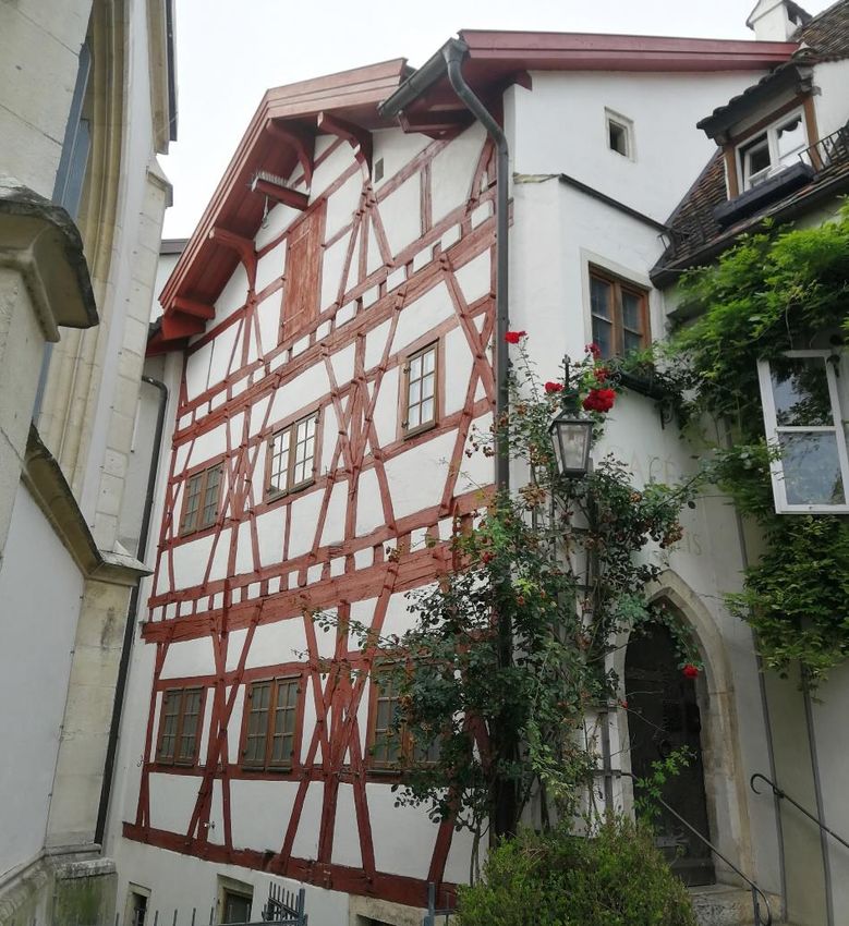
Foreword
This report represents the first publication of the InFutURe Wood project - Innovative Design
for the Future – Use and Reuse of Wood (Building) Components.

InFutUReWood is supported under the umbrella of ERA-NET and financed by funding agencies
from each of the participating countries. The industry partners participate mostly with in-kind.

The research and academia project partners are RISE (Sweden), Edinburgh Napier University
(UK), National University of Ireland Galway (Ireland), University College Dublin (Ireland),
Polytechnic University of Madrid (Spain), University of Ljubljana (Slovenia), Aalto University
Helsinki (Finland), and Technical University Munich (Germany).

The industry partners are Kiruna Municipality Technical Service, Swedish Wood, Derome,
Isotimber, Offsite Solutions Scotland, Hegarty Demolition, SIP Energy, Connaught Timber, The
Federation of the Finnish Woodworking Industries, Jelovica, The Swedish Federation of Wood
and Furniture Industry, Balcas Timber, Stora Enso, Klimark + Nova domus Hábitat, and Brenner
Planungsgesellschaft.

InFutUReWood is supported under the umbrella of ERA-NET Cofund ForestValue by Vinnova –
Sweden’s Innovation Agency, Formas, Swedish Energy Agency, the Forestry Commissioners for the UK,
the Department of Agriculture, Food and the Marine for Ireland, the Ministry of the Environment for
Finland, the Federal Ministry of Food and Agriculture through the Agency for Renewable Resources for
Germany, the Ministry of Science, Innovation and Universities for Spain, the Ministry of Education,
Science and Sport for Slovenia. This is supported under the umbrella of ERA-NET Cofund ForestValue,
and ForestValue has received funding from the European Union’s Horizon 2020 research and
innovation programme under grant agreement N° 773324

                                                 3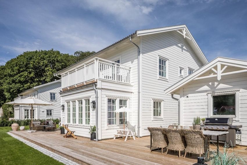
Summary
This report is a state-of-the-art on timber construction in selected european countries and
discusses technical premises for a potential circular use of timber in building construction,
focusing on Design for Deconstruction and Reuse (DfDR) in low-rise timber buildings, up to 3
storeys. It describes the historic and contemporary building techniques of timber buildings in
all project countries (Sweden, Finland, Ireland, UK, Spain, Germany, Slovenia) and finds, that
all of these countries have a long history of building with timber, but in most regions other
materials dominated the housing output from the beginning of the 20th century. Only in the
second half of the 20th century timber started gaining importance as a building material in
Europe again, with light timber frame construction becoming an important construction
system. From the beginning of the 21st century, innovations in the sector started transforming
the construction industry. Mass timber products like CLT opened the market for high-rise
timber buildings and in some countries office blocks, schools and hotels are built using timber,
although the majority of timber construction remains residential. An even more important
development might be the uptake of offsite construction, that makes timber construction
more accurate, material efficient, fast and it reduces waste These modern methods of
construction are gaining importance in the construction sector of all partner countries and are
likely to dominate the European housing output in the future. There will be some regional
differences in the level of prefabrication, material choices and designs, so that any design
guidelines for DfDR need to be adapted to the regional context. However, modern timber
construction is not currently aligned with circular economy principles and is seldomly taking
buildings end-of-life-into account.

Therefore, the report continues to summarise novel design concepts for deconstruction and
reuse, that could be used in modern timber buildings. It outlines that the feasibility as well as
the reuse potential depends on the scale of reclaimed components, where larger components
and assemblies are often considered beneficial in terms of time, greenhouse gas emissions
and waste production. If volumetric or planar units could be salvaged in the future, they also
need to be adaptable for altered regulations or standards or alternative functions. It is further
necessary that assemblies can be altered within buildings, since different building components
have different life expectancies. Various examples for DfDR in buildings with the
accompanying design strategies are presented. The buildings in the examples are often
designed to be in one place for a limited timeframe and can be deconstructed and re-erected
elsewhere without replacement of components. Key-features often include modularity of
components, reversible connections, adaptability of the floor-plan and circular procurement.
Even though it is evidently possible, the structural reuse of timber is not a wide-spread
approach to date. Barriers to the use of reclaimed structural components are mainly a lack in
demand for salvaged materials, but also prohibitive building regulations and the lack of design
standards. Demolition practices play a crucial role as well and need to be considered in the
design of buildings, to avoid damage to the components.

Finally, the report summarises principles and guidelines for DfDR by different authors. As a
generic approach an indicator system for deconstructability and reusability could be
introduced. Time, Separability, Risk and Safety, Simplicity and Interchangeability are identified

                                               4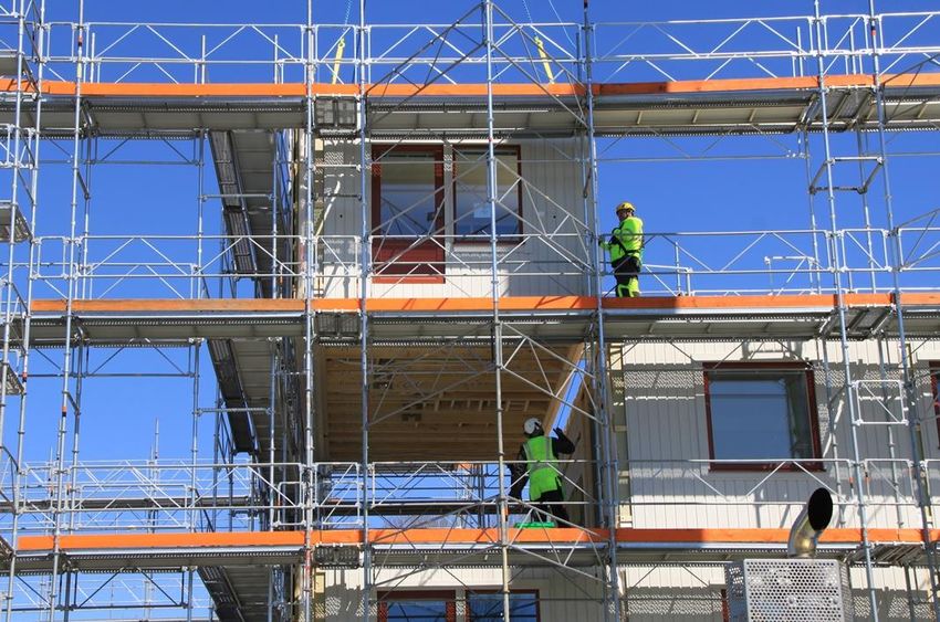
as the main indicators for DfDR, that remain somewhat abstract. As opposed to using a generic
indicator system, a more practical approach of assessing DfDR on an individual basis could be
taken. This way specific shortcomings of the design can be addressed. But if DfDR found a
wider application in the future, this approach may be too time consuming and there is a need
for a more directed decision-making tool that can be used during the design phase of buildings
to enhance DfDR. As the InFutUReWood project proceeds, it will examine a more granular
approach to DfDR, relating it to the actual construction stages used in practice, developing a
general template to be appropriated and adjusted to account for regional variations in
construction. A strategic matrix is in development which will provide designers with a
methodology based on relating principles, strategies and specific tactics to the typical design
stages, to aid design decisions that promote DfDR.

                                              5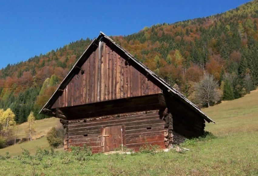
Table of contents
1.      Introduction                                                                           9
     1.1.     Background                                                                       9
     1.2.     Aim & Objectives                                                                 9
     1.3.     Method                                                                           9
     1.4.     Limitations                                                                      10
     1.5.     Short glossary of terms                                                          10

2.      Reuse in circular timber construction                                                  12
     2.1.     Circularity in the building sector                                               12

3.      Timber building design: potentials and obstacles for future reuse                      20
     3.1.     Building systems and processes                                                   20
        3.1.1. Timber construction systems                                                     20
        3.1.2. Timber construction in selected countries                                       30
     3.2.     Novel design concepts with respect to deconstruction and reuse                   48
        3.2.1. Design for Deconstruction and Reuse                                             48
        3.2.2. Scale in design for deconstruction and reuse                                    50
        3.2.3. Changes in buildings. The role of structure                                     54
        3.2.4. Examples of wooden buildings with DfDR design philosophy                        56
     3.3.     Benefits and obstacles for reuse of structural timber                            61
        3.3.1. Benefits of reuse of structural timber                                          61
        3.3.2. Obstacles for the reuse of structural timber                                    62

4.      Principles, indicators and guidelines for Design for deconstruction and reuse (DfDR)   66
     4.1.     Case Study Approach                                                              71

5.      Conclusions                                                                            73

6.      References                                                                             75

7.      Annex 1                                                                                86

                                                          6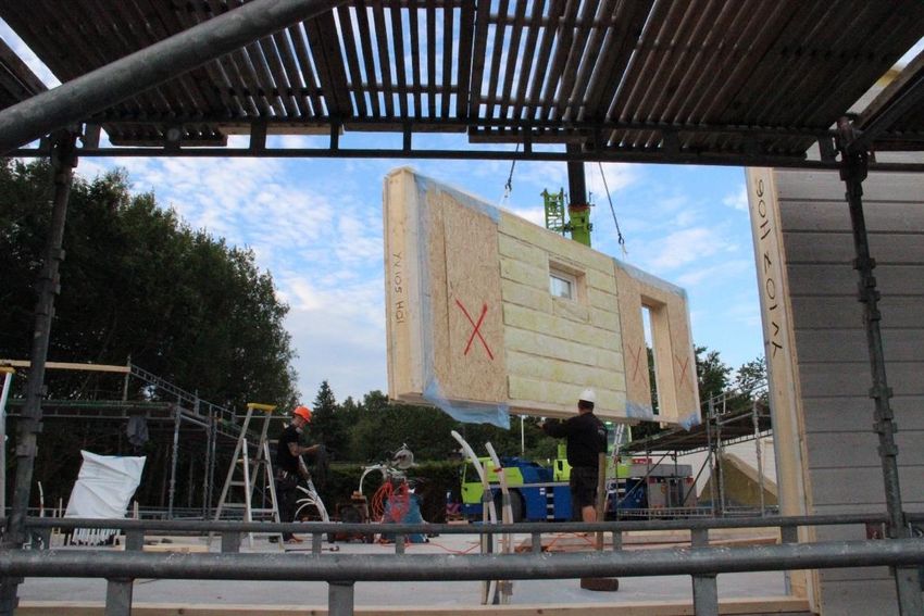
Table of Figures
Figure 2.1 Conceptual model of sustainable construction (Kibert 1994) ......................................................... 12
Figure 2.2 Lansink's waste hierarchy with explanations to the right (Lansink 2017) ....................................... 13
Figure 2.3 Circular economy systems diagram (2019) Source: MacArthur 2020 .............................................. 14
Figure 2.4 Potential cascading of pine wood. Fraanje (1998), adapted by Icibaci (2019) ................................. 15
Figure 2.5 Illustration of wood circularity with its carbon cycle (Bergkvist and Fröbel, 2013) ......................... 16
Figure 2.6 Changing the life cycle in the domain of built environment from linear to cyclic model through
disassembly of buildings (Crowther, 2005) ............................................................................................ 18
Figure 2.7 Waste management hierarchy for demolition and construction operations, adapted from Kibert et
al. (2000) ............................................................................................................................................... 19
Figure 3.1 Example of onsite light frame family house (photo: D. Honfi) ........................................................ 21
Figure 3.2I-joist structural elements on metal joist hangers (photo: Steico 2020)........................................... 22
Figure 3.3 Post and beam frame (photo: D. Honfi) .......................................................................................... 23
Figure 3.4 Traditional log construction from year 1830,”Bonnstan”, Skellefteå, Sweden (Photo: Karin
Sandberg) .............................................................................................................................................. 24
Figure 3.5 Traditional construction in Norway, a combination of post-and-plank in the front area, and log
construction in the back area (Photo: E. Shotton) ................................................................................. 25
Figure 3.6 CLT Wall panels craned into position on construction site (Strongtie 2019) ................................... 26
Figure 3.7 Lifting of large prefabricated wall element in Sweden (Courtesy of Derome AB) ........................... 27
Figure 3.8 Example of a Structural Insulated Panel (SIP) used in e.g.Ireland (Courtesy of SIP Energy) a)
positioning in the wall; b),c) panel joint connections............................................................................. 28
Figure 3.9 IsoTimber block composition: studs with air ducts placed next to each other, vertical plywood
boards glued on each of the large sides (IsoTimber 2018) ..................................................................... 29
Figure 3.10 Assembly of multi-storey building made of volumes (Courtesy of Derome AB) ............................ 30
Figure 3.11 Single-family house “Villa Anneberg”, year 2018, one of the case-studies chosen in the project
(Photo: Husfoto, via Derome) ................................................................................................................ 31
Figure 3.12 Inner harbour in Sundsvall, Sweden, year 2004. Five apartment blocks, from right to left: three
blocks with a structural frame made from CLT, and two blocks with a light-frame building system. The
wooden façade is of glulam cladding. Photographer: Per Bergkvist (Swedish Wood 2020) ................... 32
Figure 3.13 ” Sara” Cultural Centre and Hotel in Skellefteå, Sweden will be 80 meters high and have 20
storeys. The total volume of the structure will be 10.000 m 3 CLT and 2200 m3 glulam delivered by
Martinsons. Photo: Jonas Westling (Sara, 2020) .................................................................................... 33
Figure 3.14 The old town of Porvoo, Finland, with well-preserved 18th century wooden buildings. (Photo:
Bahareh Nasiri)...................................................................................................................................... 34
Figure 3.15. Perspective view of a standardized balloon framed timber house in Finland. Type A9, designed in
1952. (Source: Metsätalousministeriö, 2020) .................................................................................... 35
Figure 3.16 Residential building in Kuninkaantammi, Helsinki, year 2018. Developer: A-Kruunu
OyArchitectural design by ARK-house arkkitehdit Oy, Wood Structural design by Sweco (Photo by Jari
Härkönen) ............................................................................................................................................. 36
Figure 3.17 Modern timber house construction in Scotland, year 2005, light-frame and prefabricated panels
(Photo: D. Ridley-Ellis) ........................................................................................................................... 37
Figure 3.18 Conventional one-storey Irish Bungalow (Photo: SJ Walsh).......................................................... 38
Figure 3.19 Conventional mid-20th century load-bearing masonry house in Ireland (Photo: SJ Walsh) ........... 39
Figure 3.20 Wall construction of a typical Corrala house type (Drawing: M. de Arana Fernández) ................. 41
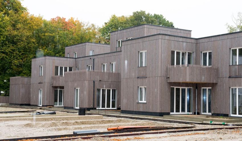
Figure 3.21 Half-timber house in Eichstätt, south Germany (photo: R Ivanica) ............................................... 42
Figure 3.22 Modern timber frame building (2019) in the newly developed residential area “Prinz-Eugen-Park”
in Munich (Photo: Ralf Rosin, TUM)....................................................................................................... 44
Figure 3.23 Old traditional wooden hut with shingles made of larch, in Kranjska Gora (Photo: Žiga Krofl) ..... 45
Figure 3.24 Solid timber house for a family of five, year 2017, in Savinjska. Photo: Lesoteka hiše d.o.o. ........ 46
Figure 3.25 Areas of concern to DfDR Crowther (2005) a modified representation of a model for sustainable
construction based on Kibert (1994) ...................................................................................................... 50
Figure 3.26 Hierarchy of building components considering reuse (Hradil 2014) .............................................. 51
7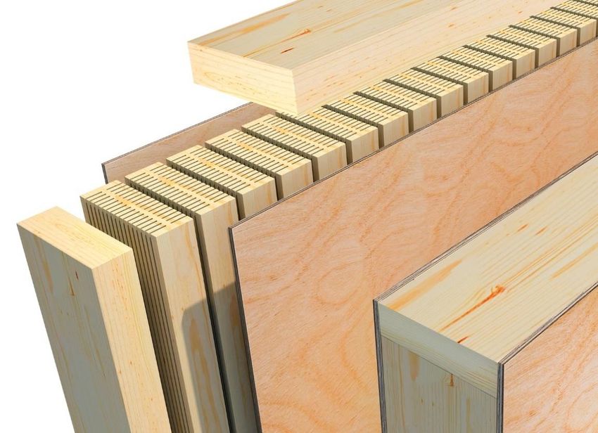
Figure 3.27 Design for deconstruction and reuse issues will depend on scale. The scale is affected both by the
      type of building system used (vertical) and by the type of components that are to be deconstructed and
      reused (horizontal). (Drawing: SJ Walsh after an idea by Y Sandin). ...................................................... 53
Figure 3.28 Techbuilt diagram (1954) and interior photos of custom Shikoku Techbuilt house, Johnson et.al,
      2020 (Shikoku images are from a Techbuilt catalogue, circa 1973, from the collection of Jeff Adkisson,
      see https://thetechbuilthouse.com/)..................................................................................................... 56
Figure 3.29 Brummen Town Hall, the Netherlands. Wooden structure planned for reuse (courtesy of Petra
      Applhof) ................................................................................................................................................ 57
Figure 3.30 Glulam beams with metal connections, Bullitt Center (Courtesy of Bullitt Center, photos by John
      Stamets). ............................................................................................................................................... 58
Figure 3.31 Fielden Fowles Architecture Studio (Source: Johnson et al. 2020) ................................................ 59
Figure 3.32 Temporary Market Hall, Östermalm (Photographer: Felix Gerlach).............................................. 60
Figure 3.33 Building D-mountable 2020, Delft, Holland. © architectural office cepezed (Photo: MetsäWood
      2020) ..................................................................................................................................................... 61
Figure 4.1 Assessment model with related spin diagram offering information on aspects that can be
      improved in order to increase the disassembly of structures and their associated reuse potential.
      (Durmisevic, 2019)................................................................................................................................. 66
Figure 4.2 The ten main principles of DfDR (Guy and Ciarimboli, 2008) seen as indicators of Design for
      Deconstruction and Reuse (Source: RISE) .............................................................................................. 69
Figure 4.3 Main indicators of a) Deconstructibility (Thormark 2001) and b) Reusability (Hradil et al. 2017) ... 70

                                                                                8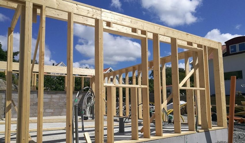
1. Introduction

1.1. Background
This delivery is part of the InFutUReWood - Innovative Design for the Future – Use and Reuse
of Wood (Building) Components – project which aims to answer two main questions:

   1. How easy is it to reuse wood from current buildings, especially as structural material?
   2. How can the past experience help the future?

To address these questions the project’s objective is to identify the key opportunities and
challenges, and to propose technical and methodological solutions. This knowledge will be
transferred to industry to avoid inadvertent and unnecessary problems for future generations.

Within the project Work Package (WP) 2 Design of timber structures for the future aims to
develop building concepts that optimize the design of wooden buildings to enhance resource
efficiency and deconstruction. This deliverable is the result of the work carried out within Task
2.1 Study new ways to design structures and details to facilitate recovery of materials, meeting
building regulations and standards of different countries, and investigate need for future
changes of WP2.

1.2. Aim & Objectives
The aim of this report is to provide an overview about the state of the art regarding timber
construction and reuse of timber structural elements in particular. To achieve this several
objectives are set out:

   •   Identify timber construction types for developing promising concepts for reuse;
   •   Identify obstacles and potential for reuse of structural timber;
   •   Identify (and possibly adapt) existing methods for the evaluation of reusability of
       wooden structural members.

1.3. Method
The report gathers together information studied and selected by the authors from different
sources: scientific articles, books, websites of manufacturers, of research institutes, website
focused on architecture, but also interviews with key-actors in the project, industry partners
and branch organisation representatives. The study is mainly qualitative with a collection of
quantitative data about the actual trends in timber buildings across the seven countries.

                                               9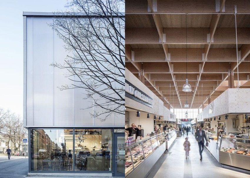
1.4. Limitations
The report is focused on timber buildings; thus, it may not be possible to directly generalise
findings for other construction materials. Similarly, results and solutions regarding other
buildings materials may not be directly transferred to wood buildings, though principles and
strategies will be examined with both general and specific construction in mind.

The focus of the Work Package 2 is on the design phase as opposed to the operation and
management of timber buildings. Many principles regarding design for deconstruction
emphasize the importance of engaging with clients and the design team at an early stage, best
described as conceptual planning in the pre-design phase, which will be discussed in this
report but will not form part of later design studies in WP2. The study has focused on housing
stock, as being the building type in which the greatest quantity of timber per square meter is
found. Equally important, from a social and environmental standpoint, focussing on this
typology is potentially of greatest benefit, as construction of residential projects outstrips
other such sectors significantly. More precisely, later stages of the study will focus on: the
primary design of 1-4 storey wooden houses for flexibility, adaptability and to facilitate
deconstruction; and to use materials in a resource efficient manner and make it possible to
separate materials for more efficient material recovery in the future. Designing the structures
in this way will then influence deconstruction, waste management and designing with reused
materials in the future.

1.5. Short glossary of terms
A full glossary of terms can be found in Annex I.

The most used terms in the report are defined as follows:

Design for Deconstruction and Reuse (DfDR) is the design of the building so that the parts are
easily dismantled and separated from each other for reuse or recycling (Moffatt and Russel
2001). The main focus is on component preservation (reuse, repurposing) before material
preservation (recycling).

Recycling is any recovery operation by which waste materials are reprocessed into products,
materials or substances whether for the original or other purposes. It includes the
reprocessing of organic material but does not include energy recovery and the reprocessing
into materials that are to be used as fuels or for backfilling operations. (EC 2008).

Reuse is any operation by which products or components that are not waste are used again
for the same purpose for which they were conceived, with minimal pre-processing, i.e.
checking, cleaning and repairing. (Adapted from EC 2008).

Timber is used here to refer to any wood-based building material, whether structural or non-
structural. Depending on the context, the word is used to refer to sawn wood in a prepared
state for use in building (or wood intended for that purpose), but it can also be used in a
general sense to include laminated elements and other engineered wood products. Wood

                                              10
based panel products are not, themselves, referred to as timber, but they do fall under the
general heading of timber construction. In some countries, timber refers to specific end-uses
and/or cross-section sizes, but that distinction is not made here (Adapted from ISO 6707-1
(2020).
112. Reuse in circular timber construction
2.1. Circularity in the building sector
Circular Economy (CE) is described by Geissdoerfer et al. 2017 as “a regenerative system in
which resource input and waste, emission, and energy leakage are minimised by slowing,
closing, and narrowing material and energy loops. This can be achieved through long-lasting
design, maintenance, repair, reuse, remanufacturing, refurbishing, and recycling”.
In “A Critical Literature Review of Concepts” (Beaulieu et al. 2015) the authors discuss the
different meanings of the definitions found in the literature: some of them claim CE to be
based on effectiveness (“doing the right thing”) but many definitions from various
organizations seem to focus on efficiency (“doing things right”), while some concepts such as
Functional Economy aim to reconcile both (“doing the right thing the right way”). This can be
paraphrased by adding “in the right moment”, a concept best illustrated by the model for
sustainable construction (Figure 2.1) by Kibert (1994), which will be discussed in more detail
in Section 3. By this the authors emphasize the importance of the design stage, of planning for
circularity from the very beginning of a construction project.
Figure 2.1 Conceptual model of sustainable construction (Kibert 1994)
An appendix with preliminary glossary of definitions most often used in the context of building
process as part of CE can be found in Annex 1.
For all industries, not only in building industry, materials flow and management is the common
denominator across all value chains. The European Union through its strategy (CEAP 2020)
that has led to the launch of national initiatives (such as in Sweden, Swedish Government
2020) supporting the idea that business must adapt itself to circularity by changing its models
in order to gain the most value from circulating in loops.
12There are five important technical (and value creating) loops in CE, where the most immediate
loop, product maintenance (the ‘inner circle’ or ‘Waste prevention’), yields the highest value
and the loop furthest downstream (reprocessing material) yields the least value:
1. Product maintenance
2. Product reuse/redistribution
3. Product refurbishment/remanufacture
4. Product recycling
5. Reprocessing of technical nutrients. (Beaulieu et al. 2015)
The loops of CE described above are strongly connected to the waste hierarchy concept. In
the Netherlands, following a parliamentary proposal in 1979, a “waste hierarchy” was
developed with a preference order for waste management: from prevention, reuse of
products, recycling of materials, energy generation through incineration to functional
landfilling (Figure 2.2).
Figure 2.2 Lansink's waste hierarchy with explanations to the right (Lansink 2017)
The majority of wood from the construction and demolition (C&D) sector, depending on each
countries' legal regulations, regional and technological situation, is mostly incinerated for
energy recovery or landfilled (with great differences across European countries, Vis et al.
2016). Only about one third of C&D wood waste in Europe is currently recycled into material
for board products (Risse et al. 2017). There is debate (Seltenrich, 2013) on the term wood
recycling, as waste management companies are using this term to describe the incineration
for energy recovery but, according to Lansink (2017) and the EU, recycling refers to materials
being transformed into new products.
Wood has a special place in the circular scheme, as shown by McArthur (2020), see Figure 2.3
It is a biodegradable material that belongs to “renewables” and it should therefore strive to
follow such a scheme and, further, to be considered as carbon store. Nevertheless, wood is
also a structural building material, with a technical application. The finite materials scheme
13has been adapted to construction and the finite materials used within it to inspire the reuse
of concrete or steel but has been very rarely applied to wood.
In Figure 2.3 the study and the aim of this project could be positioned in “cascades” on the
left side of the graph (Renewables) but actually the aim of transforming the wood building
industry from a linear to a circular type can be fulfilled by considering the loops on the right
side of the graph as well, presented as suitable for finite materials. They are the same loops
as described by Beaulieu et al. 2015 and we argue that the way renewable materials are used
should receive the same consideration as finite materials before being considered “biomass”.
Figure 2.3 Circular economy systems diagram (2019) Source: MacArthur 2020
The concept of “cascading” was developed in the Netherlands with the aim of better resource
efficiency by Sirkin and ten Houten (1994) and referred to all types of materials. In “The
cascade chain: A theory and tool for achieving resource sustainability with applications for
product design” the authors discuss among others: “What possibilities lie in the application of
the cascade concept for the appropriate exploitation of the intrinsic and extrinsic properties
of resources, substances, materials and products?” The concept was later applied to wood by
Fraanje (1998), as seen in Figure 2.4.
14Figure 2.4 Potential cascading of pine wood. Fraanje (1998), adapted by Icibaci (2019)
Given the development towards a more climate friendly and resource efficient bio-based
economy, the demand for wood will increase in the next years and likely exceed the supply
that is currently available from a sustainable forest management (Mantau et al. 2010).
Developing and applying the concept of cascading can contribute to satisfying this increasing
demand.
The term cascading was coined by the biomass sector (see Figure 2-3) but the principle is the
same for all materials, briefly: material use first, energy use last (Arnold et al. 2009). In 2017
it was considered that a consistent definition of the term “cascading use” was lacking across
all sectors including science, economics and politics (Fehrenback et al. 2017). Moreover, the
integration of a cascade approach into existing legislature has differed widely among
individual countries, as well as the associated effects. It is noticeable that the term “cascading
use” has been included in both German and European strategy and position papers since
about 2010, most frequently in explicit reference to biomass use.
The ability of the forest to absorb the carbon dioxide emitted by the incineration of timber
(Figure 2.5.) as it grows has been something of an impediment to the successful
implementation of wood cascading in European countries. The general perception has been
that the carbon cycle and the fibre reuse cycle already assure the circularity of wood (Figure
2.5). The importance of reusing a wooden product without downcycling it, without reducing
it to a source of material for another product, without milling it, has been neglected especially
in countries with significant forest cover. Instead there was more focus on biochemical and
thermochemical conversion of wood, which is also important in terms of circular economy,
but focuses more on virgin wood rather than recovered wood as a resource.
15Figure 2.5 Illustration of wood circularity with its carbon cycle (Bergkvist and Fröbel, 2013)
Prolonging and diversifying the use of the same resource, via cascading, is the most useful
strategy for reducing waste (Figure 2.3). As defined by Risse (2019), cascading refers to the
sequential use of one unit of a resource in multiple material applications and, in the case of
wood, ends with its use for energy generation through incineration. As Risse explains “It
follows a holistic perspective on the material’s value chain and can include various reuse and
recycling processes as well as end-of-life treatments” (2019). The cascade use of recovered
material also reduces the environmental impacts associated with product manufacturing.
Furthermore, cascading can increase the time of carbon storage and postpone carbon
emissions, with potential benefits for climate change mitigation (Maguire, 2018).
To further enhance wood cascading in practise, new recycling technologies and product
applications are required and were under research in recent years. Some research activities
revealed that the use of recovered wood is technically possible (e.g. Irle et al. (2015); Lesar et
al. (2016); He et al. (2019)). However, due to the heterogenic and often low quality of the
recovered wood, only small yields are obtained for high value recycling processes (Privat
2019). Thus, cascading not only required new technologies, but also a different demolition
and waste treatment in order to increase material quality. Ideally, products and buildings
should be designed in a way that preserves the material’s quality and enables easy and
efficient recycling.
16Here, wood buildings may receive greatest attention for several reasons. Currently, most of wood from building demolition is mostly incinerated for energy recovery (especially heat in power plants) and a very small amount is still landfilled, tending to each, see Table 1, (data for 2016 partially collected from Bioreg, 2017). Table 1 Share of waste wood sent to landfill in 2016 and 2018 in selected countries Country Finland Ireland Germany Slovenia Spain Sweden UK Year 2018 2016 2020 2016 2016 2020 2018 Wood to landfill (% of total 0,06 3,39 0 0,01 1,65 0
(2019) argues that the main strategy to close material loops for buildings at the end of their
useful life is reuse.

In Europe the international projects focused mainly on structural materials that had showen
to affect the environment and that are non-renewable, such as concrete in RE4 (Attanasio and
Largo, 2017) or steel in PROGRESS (Hradil et al. 2017). The transition to a bio-based economy
that takes place in many European countries puts pressure of the availability of wood, it will
be used resource material for numerous products and applications. Lundmark (2020) showed
that a fossil-free Sweden in 2045 would mean an increase in the need of quantities of wood.
The requested amount will not be available by that time, taking also into account that the
forest should keep its biological diversity and provide the absorption of carbon dioxide. That
is why it is highly important to reconsider how wood structures are seen by society, they
should also be part of the “material bank”, and be reused as structures and components.

Such an effort requires a transition from linear to a circular construction model (Figure 2.6)
even for timber buildings. In a linear model, buildings are made of materials extracted from
natural resources, then processed into materials, manufactured into components, assembled
into buildings, used and then after the end of their lifetime demolished followed by being sent
to landfill or incineration, depending on material and country.

Figure 2.6 Changing the life cycle in the domain of built environment from linear to cyclic model
through disassembly of buildings (Crowther, 2005)

In a circular model, waste is prevented and reduced through various processes after
disassembly including: complete or partial relocation of the building, reuse of components or
subassemblies, recycling of building materials into new components, or reprocessing into new
materials. The “smaller” the cycle the larger the expected environmental benefit, i.e. typically

                                                 18
relocation and reuse, are the preferred options, though maintenance, adaption or flexibility
(reuse on site) prior to relocation is optimum
This then suggests a hierarchy of waste management as proposed by Kibert et al. (2000) and
shown in Figure 2.7.
Figure 2.7 Waste management hierarchy for demolition and construction operations, adapted from
Kibert et al. (2000)
Disassembly that aims at the reuse or relocation of building components or assemblies within
a new or existing building is often termed as deconstruction (Long, 2014). During
deconstruction consideration is given to 1) dismantling without causing damage and repairing
damaged components; and 2) utilizing the remaining lifetime of the dismantled components
either for original purpose or for other purposes (Moffatt and Russel, 2001). The primary goal
of deconstruction is to reuse the dismantled components; however, recycling can also be
considered as a secondary objective. The term disassembly is often used in a wider context
and typically enables the possibility of recycling of recovered building materials into new
components or reprocessing into new materials. Thus, disassembly is typically less
environmentally friendly than deconstruction as it preserves less embodied energy and
requires additional energy for reproduction.
193. Timber building design: potentials and obstacles for future reuse
3.1. Building systems and processes
3.1.1. Timber construction systems
Various ways exist to construct buildings made of timber and wood-based products as load-
bearing components with different levels of prefabrication. These buildings range from single
family houses to high rise wooden buildings, office buildings, schools and pre-school buildings,
sport halls and multi-storey car parks. Wood, with its advantage of being lightweight
compared to its strength, has increased the capacity of building larger components, as well as
quick and easy assembly on site.
Different types of wooden building systems can be categorized based on several aspects, such
as: structural system, use of material, type of building elements, level of prefabrication, etc.
Table 3.1 Classification of timber construction systems shows how these aspects could be
arranged in different classes. The systems in use are thus a combination of these classes. A
brief summary of common modern construction systems is presented after Table 3.1.
Table 3.1 Classification of timber construction systems
Aspect Type
Structural Light-frame construction (stud frame, I-joints)
system and Post and beam
material use Massive timber construction (Log construction, Post and plank, CLT)
Prefabrication On-site building (stick building)
and automation Prefabricated (beams, columns, plane elements)
level Industrialized construction (volumes)
Light frame timber on site construction
The light-frame technique can be categorised to two techniques: first, the balloon framing
technique (maximum of two-stories) and second, the platform framing technique (more than
two-stories). The balloon frame technique consists of full-height wall framing elements which
usually use light sawn timbers, assembled with nails (Allen et al. 2017). In the platform
technique the load-bearing elements are mainly exterior walls which are built on top of the
floors, storey-by-storey. This method enables the use of smaller pieces of timber in the load-
bearing elements to create a “platform” of wood flooring, stable enough to place the supports
for the upper floor on top of it. Similar to balloon framing technique, the platform framing
20technique usually uses basic sawn wood grades. Nowadays, the load-bearing structures in
wood-frame multi-storey constructions increasingly rely on engineered wood products.
(Hurmekoski et al. 2015)
Light frame building on site method is suitable for houses built without advanced lifting
equipment, typical for single family houses but also for multi-storey buildings. Most of the
work is done on site carried out by carpenters. The common construction material is either
ready-cut timber or timber cut on site. Walls are assembled horizontally on foundation slabs
and floor with vertical studs placed between the top and the bottom plates, and the nailed
frame raised into position (Figure 3.1). After the structural frame is built, typically without
sheeting material and insulation, a protective roof is installed. When the weathertight roof is
in place, installation of moisture-sensitive materials (e.g. insulation and plasterboards) begins.
For taller buildings bracing boards are often required to ensure stabilization during the
construction process. On-site construction tends to take a longer time than prefabricated
construction (Kuzman and Sandberg 2016).
Figure 3.1 Example of onsite light frame family house (photo: D. Honfi)
Light-frame construction using I-joists
I-joist is a general term used for a light-weight engineered structural elements with a section
in the shape of I, made out of two flanges in e.g. solid wood that are connected by a web
material such as OSB or other type of wooden board (see Figure 3.2). They are used not only
as joists for floors but also as rafters in roofs and as stud elements (the latest are used in
prefabricated walls together with insulation). The benefit of the I-shape is an effective load
transfer through the cross-section, giving a lightweight product with a high ratio between
strength properties and the material consumed (Masonite 2018).
21Figure 3.2I-joist structural elements on metal joist hangers (photo: Steico 2020)
According to Persson and Wikner (2020) it possible to build high-rise wooden buildings up to
12 storeys using systems based on I-joists, also to produce floor structures with spans of up to
8 metres, with thicknesses from 413 mm. The walls can be produced in lengths up to 9 metres
and thicknesses between 300 and 600 mm.
As solutions for connecting it is mainly metal web joist hangers, such as the ones produced by
Simpson Strongtie (2020) or that are chosen in Figure 3.2 as well as variable pitch connectors,
choices based according to the loads and size of the I-joist elements.
I-joists are very popular in the UK, especially in timber frame houses, and increasingly
replacing solid timber in masonry construction too. It is quite rare to find solid wood joists in
floors as i-joists are much more normal. They are successfully used studs and roof trusses also.
Post and beam
Post and beam system are made of largely prefabricated units that are joined together on site.
They also require a weatherproof roof and often some kind of protective cover even during
transportation of the structural elements.
Post-and-beam techniques are constructed of a skeletal framework of massive columns and
beams (Figure 3.3) that the intermediate and upper floor planes, as well as the exterior walls,
are installed on top of it (CWC 2014). This technique enables large openings in façades, making
it ideal for the construction of modern architectural design (Puuinfo, 2020). The span of posts
and beams are derived by engineering calculations based on the strength and size of the
timber members, the span of the beams and infill floor joists, in tandem with anticipated
loading based on anticipated use, with the normal distance being 1200 mm or more (CWC,
2014). The beams provide flexibility in the interior, even after completion of the buildings
since the walls and dividers are non-load-bearing elements (Puuinfo, 2020).
22Figure 3.3 Post and beam frame (photo: D. Honfi)
Massive Timber Construction
Log construction
An early form of solid construction was log construction, a system with horizontal logs stacked
directly on top of each other. The load-bearing walls acts doubly as structure and enclosure,
leaving joints exposed and expressive of the construction (Mayo, 2015). The trunks can be
squared off, as in Figure 3.4, but round logs are also used in the “blockwork” type of
construction (Mayo, 2015). Log construction is still occasionally used for building summer
houses, in most cases totally handcrafted in Sweden. Industrial manufacturing, laminated logs
and finger jointing enable production of lengthy logs in Finland, allowing the construction of
large size buildings and modern architecture designs (Laukkanen, 2018).
23Figure 3.4 Traditional log construction from year 1830,”Bonnstan”, Skellefteå, Sweden
(Photo: Karin Sandberg)
Post and plank construction
According to Rybníček (2018) world’s oldest dendrochronologically dated archaeological
wood construction, year 5481 BC, was a post and plank type, in oak, discovered near Ostrov
(Czech Republic). This confirms Mayo’s (2015) statement that using vertical logs to create a
skeletal load-bearing structure is one of the oldest forms of building and developed in parallel
with blockwork construction.
Unlike the blockwork construction, skeletal frame timber buildings do not rely on stacking and
massive exterior walls to crate stability. Rather than relying on gravity, these structures rely
on sometimes exceedingly complex wood joinery for stabilization (Mayo, 2015).
An example of a post and plank construction is presented in Figure 3.5.
24Figure 3.5 Traditional construction in Norway, a combination of post-and-plank in the front
area, and log construction in the back area (Photo: E. Shotton)
CLT construction
Cross laminated timber, crosslam, CLT, X-Lam, BSP, mass timber and multiply are common
names for sheets, panels, posts and beams made of glued boards or planks layered alternately
at right-angles (Gustafsson, 2019). CLT panels are made up of boards or planks with a thickness
of 20 – 60 mm. This surface timber product is typically fabricated by laminating three to nine
layers of timber boards with each layer typically placed at 90 degrees to the next (as in
plywood), although studies exist on 45 degrees layering (Buck et al. 2016).
In relation to their own weight, CLT panels have a higher load-bearing capacity than most
other construction materials, which is why large structures can be built to withstand high loads
(Gustafsson, 2019). Panel dimensions vary, with the common largest proportions of length,
25width and thickness between 18m, 5m and 0.5m (Harte, 2017). The length can sometimes
reach 30 m (Gustafsson 2019).
CLT panels are used for the primary above ground structure of walls, floors and roofs and
assembled with the use of cranes (Figure 3.6). The external walls have a load-bearing and
stabilizing function, and have to be insulated to give the building a high level of energy
efficiency in colder cliamtes. Internal walls for stabilization are made of CLT, while sound-
insulating walls between rooms sometimes are of traditional timber-frame structure (Kuzman
and Sandberg).
Figure 3.6 CLT Wall panels craned into position on construction site (Strongtie 2019)
Buildings of up to 18 storeys in height have been constructed (Brock Common’s Student
Residence, Canada), with studies suggesting that very tall structures using CLT are feasible
(Harte, 2017). An example of a “pure” tall solid wood building that has concrete only as a
platform is Origine, built in 2017 in Quebec, Canada. It is 40,9 m high and 13 storeys out of
each 12 storeys are build entirely in solid wood, predominantly in CLT with help of glued-
laminated timber (posts and columns), supported by a concrete podium (Nordic 2017).
According to Gustafsson (2019) there are many different types of fixings that can be used in
designing joints between CLT walls and floor slabs or joints between other materials and CLT.
Long self-drilling wood screws are commonly used in joints between CLT panels (Wilded, 2020)
but other traditional fixings such as nails, inset plates and nail plates are also widely used.
There are also several more innovative solutions such as glued-in rods, advanced package
solutions that cover all corner solutions, including assembly fixings and systems for invisible
26load-transferring joints. The new systems often rely on a high degree of prefabrication of CLT
panels and the fact that CNC machines are used to design fixings (Gustafsson 2019).
In central Europe, wooden dowels are becoming more and more popular as connectors, such
as the products by Knapp (2020).
Prefabrication and automation:
To reduce the construction time on site, parts of the structural frame can be modularized into
planar structural elements, such as floor units and walls (Figure 3.5), or volumes.
Planar structural elements
Planar structural elements are generally of two types: small and large. Sizes of a small planar
elements are produced up to 1.2m wide and are lightweight and compact to enable a crew of
two workers to set up a house without the need of a crane. The large planar element are an
up-scaled version of the small unit system in which the sizes of are assembled up to 22 metres
long (Siikanen, 2008). Due to the size and weight of the large prefabricated units, a crane is
essential in the construction process (Figure 3.7).
Figure 3.7 Lifting of large prefabricated wall element in Sweden (Courtesy of Derome AB)
The technique for manufacturing planar elements and the connections between materials
differ between construction systems and countries. The most common system in Sweden,
27Finland, Slovenia, and the UK are panels where the insulation material is inserted between
studs and joists in a light-frame type construction, but structural insulated panels (SIP) are also
used in the UK and Ireland.
SIP
SIP is a sandwich system composed of an insulating layer of rigid core (a type of foam) glued
on each side to two structural boards (also called skins), which most commonly consist of
Oriented Strand Board (OSB) (Figure 3.8a). Two of the most widely used panel joint
connections are the surface spline and the block spline (Simon 2020, Figure 3.8b, Figure 3.8c).
In Ireland SIP Energy is the sole manufacturer of wood-based SIP panels which mainly have a
domestic use.
a) b) c)
Figure 3.8 Example of a Structural Insulated Panel (SIP) used in e.g.Ireland (Courtesy of SIP
Energy) a) positioning in the wall; b),c) panel joint connections
In the UK, SIP had around 5% of the offsite construction market share in in 2012 (Research
and Markets, 2012).
Isotimber
It is a unique type of load-bearing and insulating exterior wall. A building blocks consist of
studs, placed next to each other, supported by vertical thin (6 mm) plywood board glued on
each side, see Figure 3.9 . The air ducts that are milled in the studs provide insulating
properties. A planar element (wall) contains at least two layers of building blocks. They are
available in three thicknesses 60mm, 100 mm and 150 mm (IsoTimber, 2020)
28Width and length of the wall element are of maximum 3.1 m x 8 m, to fit transport
requirements. The dimensions are adapted based on the individual project's design and
technical requirements. They are assembled together with wrap joints and wood screws on
the construction site, all joints are taped to get a building with good air tightness.
Figure 3.9 IsoTimber block composition: studs with air ducts placed next to each other,
vertical plywood boards glued on each of the large sides (IsoTimber 2018)
The building engineers calculate frame dimensions and provide assembly drawings for the
contractor as well as manufacturing drawings for the own factory, located in in Östersund,
Sweden. This small-size company is project partner and further studies about possibilities for
reuse of the blocks and of entire walls will be presented in following reports.
Volumes (volumetric units)
Volumes are boxes with openings containing one or several rooms often including electric and
plumbing installations pre-installed at the factory before onsite construction (Hurmekoski et
al. 2015); only levelling the ground, laying the foundations, and making connections to the
sewer system are carried out on-site.
An assembly of a building made of volume elements is shown in Figure 3.10. This form of
construction offers benefits in allowing for construction higher than six floors, reducing waste
29in the factory and on-site, allowing for quick and simple on-site construction, and can be
disassembled and reassembled (Hurmekoski et al. 2015). Its limitations include an increase in
transportation costs and a loss of customization (Hurmekoski et al. 2015).
Figure 3.10 Assembly of multi-storey building made of volumes (Courtesy of Derome AB)
Future adaptability is limited, as walls along the perimeter of the volumes will be structural so
cannot be easily altered, including window and door openings, and as plumbing comes pre-
installed and stacks vertically through the building, bathrooms and kitchens cannot be moved
from their original locations (Carlsson, 2020). Finishes, whether internal or external, which
have a shorter service life, are easily replaced. As with planar elements, their successful reuse
will be dependent on any changes to building regulations and a means of guaranteeing their
performance.
3.1.2. Timber construction in selected countries
Timber construction in Sweden
Until last century in Sweden timber was the most used building material, due to the
abundance of forest land and therefor the knowledge built about timber construction. The
selection of timber for building purposes used to be made with special attention, usually only
30heartwood was used for the load-bearing parts (Björk et al. 2013). Handcrafted timber was
used for log construction until 1920. A strong sawing industry started to develop after 1870
and sawn timber became the dominant building material. From 1920 standard houses started
to be developed in cooperation with sawmills. Sweden’s effort to find prefabrication methods
can be traced back to the 1780s (Waern) and were continuously developed further on
(Schauerte 2010), which contributed to the actual situation where 80% of the single-family
houses are built off-site. Compared with other countries, Sweden was not affected in the same
way by the Second World War during the mid-20th century. This influenced to some extent the
evolution of building industry and also of the type of building technology that was used. The
traditional timber frame building technology continued to be used for one family houses but
for multi-storey residential buildings and for non-residential buildings, concrete became the
most used material.
Nowadays 95% of the single-family houses are built in wood and the light-frame system (based
on timber studs) continues to be the most used (Figure 3.11).
Figure 3.11 Single-family house “Villa Anneberg”, year 2018, one of the case-studies chosen
in the project (Photo: Husfoto, via Derome)
Walls consist of plane elements made of vertical studs with insulation material inserted
between the studs and usually faced inside with gypsum or wood-based panel materials, and
outside with a type of façade covering. The façade covering can be brick, plaster or timber.
The level of completion in the factory varies depending on the choice of façade covering,
because only timber façades can normally be prefabricated and mounted in the factory. The
floor structure is prefabricated in the same way as the walls (Kuzman and Sandberg 2016). A
31share of 80% of single-family wooden houses is built off-site and the strategy is either
manufacturing plane elements in the plant and transporting them to the site for final assembly
or, in most of the cases, assembling in the factory in complete volumes and then shipping
volumes to the building site. With prefabricated wood modules, the total cost is up to 20-25%
lower than to building on-site. This is partly due to a time saving of up to 80% on-site; on-site
assembly of the building until the roof is constructed takes 1-2 days. (Kuzman and Sandberg
2016).
Concerning multi-storey houses, three-story houses were the most common type of house,
most of them built after 1945. Nowadays the off-site manufacture with light-framing that
dominates single-family house construction is also becoming more and more common for
multi-storey housing but the CLT construction type is used, see Figure 3.12.
Figure 3.12 Inner harbour in Sundsvall, Sweden, year 2004. Five apartment blocks, from right
to left: three blocks with a structural frame made from CLT, and two blocks with a light-
frame building system. The wooden façade is of glulam cladding. Photographer: Per
Bergkvist (Swedish Wood 2020)
Generally during the 20 th century it was not allowed to build multi-storey buildings in
timber (as a result of previous fire incidents in the 19 th century), but when the country
joined the European Union in the beginning of the 1990s, building regulations were
changed allowing for significant development of multi-storey timber buildings together
with relevant standardisation and regulatory processes, which led to various types of
buildings systems. The techniques for building multi-storey timber buildings was also
influenced by the research work with mass timber constructions that started in the 90’s
on cross laminated timber (CLT). The CLT systems developed in Central Europe were used
in some cases in combination with glulam structures (Gustafsson, 2019)
32After 2015 the development has further accelerated due to environmental considerations and
the increased need for affordable new housing. Currently, the use of timber as a construction
material in multi-storey buildings has increased from 13% in 2018 to approximately 20% at
the end of 2019 (TMF, 2020).
The architectural and engineering construction industry is now planning more higher
timber buildings in Sweden (Landel, 2018).
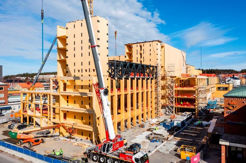
In the northern part of Sweden, the municipality of Skellefteå builds a 19-storey cultural centre
with hotel in wood that will be completed by 2021 (Figure 3.13). It is a rare example of modular
off-site building using CLT and glulam for the hotel rooms (SVT, 2020).
Figure 3.13 ” Sara” Cultural Centre and Hotel in Skellefteå, Sweden will be 80 met ers high
and have 20 storeys. The total volume of the structure will be 10.000 m 3 CLT and 2200 m 3
glulam delivered by Martinsons. Photo: Jonas Westling (Sara, 2020)
Timber construction in Finland
Until the mid-19th century log houses were the most common residential structures in
Finland, when the old wooden towns were present (Figure 3.14). The buildings in these old
towns were mostly single storey log huts; two-storey buildings only became common in towns
after the middle of the 18th century (Karjalainen & Koiso-Kanttila, 2005). There still are well
33You can also read