Momentum-transfer model of valence-band photoelectron diffraction - Nature
←
→
Page content transcription
If your browser does not render page correctly, please read the page content below
ARTICLE
                  https://doi.org/10.1038/s42005-020-0311-9                 OPEN

                  Momentum-transfer model of valence-band
                  photoelectron diffraction
                  G. Schönhense 1 ✉, K. Medjanik1, S. Babenkov1, D. Vasilyev1, M. Ellguth1,3, O. Fedchenko1, S. Chernov1,
1234567890():,;

                  B. Schönhense2 & H.-J. Elmers1

                  Recent instrumental progress of valence-band photoemission in the X-ray range allows
                  uncovering bulk- and surface-related electronic properties. Four-dimensional recording of
                  energy and momentum-vector gives access to the complete spectral-density function. Sys-
                  tematic measurements for a number of transition metals between 15 eV-6 keV reveal
                  unexpected strong intensity modulations due to photoelectron diffraction. Here, we present a
                  graphical model that illustrates the role of momentum-conservation in Fermi’s Golden-Rule in
                  an intuitive way. Intensity enhancement or reduction by factors >5 are confined to small
                  energy- and momentum-intervals (widths 0.03 Å−1 and 200 meV). Laue-type diffraction
                  involves the photon momentum and is intrinsic in the photoemission process, in accordance
                  with Pendry’s final-state-model. At higher energies, Kikuchi-diffraction imprints additional
                  modulations on valence-band-patterns and quasi-elastic background. The absence of photon-
                  momentum transfer uncovers the extrinsic nature of Kikuchi-diffraction. For Re at 30 K and
                  3.4 keV the relative weight of the Kikuchi-branch is comparable to the Laue-branch, whereas
                  at 6 keV the Kikuchi-branch prevails.

                  1 Institut für Physik, Johannes Gutenberg-Universität, Staudinger Weg 7, 55128 Mainz, Germany. 2 Department of Bioengineering, Imperial College,

                  South Kensington Campus, London SW7 2AZ, UK. 3Present address: Surface Concept GmbH, Am Sägewerk 23a, 55124 Mainz, Germany.
                  ✉email: schoenhe@uni-mainz.de

                  COMMUNICATIONS PHYSICS | (2020)3:45 | https://doi.org/10.1038/s42005-020-0311-9 | www.nature.com/commsphys                                         1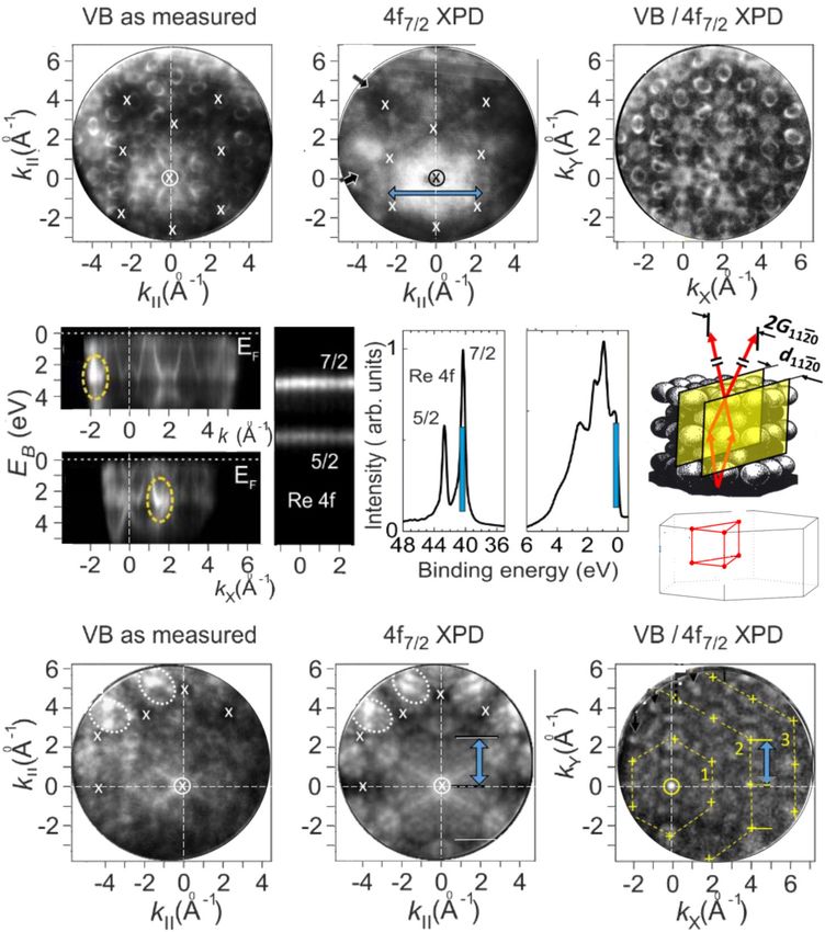
ARTICLE                                                               COMMUNICATIONS PHYSICS | https://doi.org/10.1038/s42005-020-0311-9

T
       hanks to the increased probing depth, angular-resolved             Results
       photoelectron spectroscopy (ARPES) in the X-ray range is           Momentum-space description of valence-band photoemission.
       rapidly gaining importance in solid-state physics and              Within first-order time-dependent perturbation theory, the
materials research. Access to the true bulk electronic structure is       photoemission intensity can be derived from Fermi’s Golden Rule
an important achievement, e.g. for a detailed study of correlated         describing the transition probability W from an initial state φi to a
and quantum materials. The potential of soft-X-ray ARPES is               final state φf,
demonstrated in refs. 1,2, a comprehensive overview of hard X-ray                              2π
photoelectron spectroscopy (HAXPES) is given in ref. 3.                                  W ¼ jj2 δðEf  Ei  hν Þ;                ð1Þ
   The wavelength of the excited photoelectron is smaller than
                                                                                                h
the interatomic distances, giving rise to X-ray photoelectron             where the perturbation operator Δ represents the electromagnetic
diffraction (XPD). Core-level XPD (CL-XPD) is a powerful                  field including its polarization state27,28. The δ-function accounts for
method probing the geometrical structure of the photo-emitting            energy conservation. Momentum-conservation is discussed below
atomic layers, surface reconstruction and relaxation, as well as          using a graphical intuitive model instead of a second δ-function.
adsorbate sites and distances (see excellent overviews4–12). In              X-ray photoemission is described by direct transitions into
early work angular-distributions were interpreted as being                quasi-free-electron-like final states with parabolic dispersion of
caused by photoelectron-reflection on lattice planes of the                the final-state energy Efinal versus final-state momentum kf, but
crystal13–15. A two-beam dynamical theory was applied to                  with an effective mass meff that can still differ from the free-
explain the azimuthal variations of intensities16,17. XPD cluster-        electron me
models showed fair agreement for clusters down to few nm18; at               jkfinal j=Å
                                                                                           1
                                                                                                     hÞpð2meff Efinal Þ ¼ 0:512pðmeff =me ÞpðEfinal =eVÞ;
                                                                                                ¼ ð1=
higher energies a Bloch-wave approach to XPD has proven more
appropriate8.                                                                        Efinal ¼ hv  EB þ V0* :
   CL-XPD is well understood, but thus far, data for valence-                                                                                          ð2Þ
band XPD (VB-XPD) are sparse (e.g refs. 19–23) due to the
complexity of the process. The roles of band dispersion, initial             There is no “universal” final-state parabola that is valid
electron momentum and photon momentum in VB-XPD is not                    throughout a large energy range. Rather, the final-state effective
a priori clear. Early studies in the high-energy, high-tempera-           mass meff and V0* (here referred to EF) are empirical fit parameters.
ture, low k-resolution limit revealed matrix-element weighted             For tungsten, meff/me = 1.07 at 1 keV29 and 1 at 6 keV30. For
densities of states (MEWDOS), modulated by XPD effects19,21.              molybdenum, we found meff/me = 1.035 at 460 eV and 1 already at
The results could be interpreted analogously to CL-XPD after              1.7 keV. In general, meff could be (weakly) direction-dependent.
integrating over an energy range of a few eV23 or by the                  However, we are not aware of any experimental indication of that
assumption of a localization of the band electrons19 as                   in the X-ray range. The polarization-dependence in the operator in
explained in orthogonalized-plane-wave approximation24. It                Eq. (1) causes the symmetry selection-rules31. The final state φf is
was found that the initial-state orbital angular momenta                  described as multiple-scattering state (also termed “time-reversed
influence the VB-XPD signal22. One-step photoemission theory               LEED-state”; LEED: low-energy electron diffraction) as introduced
made impressive progress at high energies25 and today is close            by Pendry et al.32–35.
to the stage of predicting VB-XPD features as shown in this                  Momentum microscopes observe a photo-transition directly in
article.                                                                  k-space, as illustrated in the k-space scheme (Fig. 2a, b) for Mo
   VB k-patterns in the hard X-ray range show a strong back-              (110). In the periodic zone scheme, each Brillouin zone (BZ)
ground from thermal-diffuse scattering, which is modulated by             contains the full set of valence bands. The spectral-density
Kikuchi-type diffraction26. Its intensity depends on temperature          ρ(EB, k) can be considered as a multitude of surfaces in 3D k-
and mass number of the relevant atom species and increases                space (one for each value of EB). Different energies then give
strongly with increasing energy and temperature, as described             different 2D-cuts (which we term energy isosurfaces) through this
by the Debye−Waller Factor. The same Kikuchi patterns are                 volume, one of which is the Fermi surface. These isosurfaces are
measured as CL-XPD at identical kinetic energy and k-field of              often fragmented into isolated electron and hole pockets and
view and can be used for a strong reduction of the modulated              appear as periodically repeated patterns, identical in all BZs. This
background. However, after this correction, regions of sig-               notion is different from the conventional description in terms of
nificant local intensity enhancements remain.                              E-vs.-k plots for certain high-symmetry k-directions. Energy
   In the present work, we discuss the different classes of Laue-         isosurfaces are a convenient basis describing XPD for itinerant
and Kikuchi-type VB-XPD and present a graphical model for                 initial states because the initial k-vectors can easily be accounted
quantitative analysis. The work was motivated by the appear-              for in the momentum-balance. The background patterns in
ance of strong local intensity modulations in valence-band                Fig. 2a, b are cuts of the isosurfaces at EF and EB = 1 eV in the
mapping of various transition metals. Figure 1 shows an over-             plane of photon incidence (here ΓNN-plane as indicated by the
view for the d-bands of Mo(110), W(110), Re(0001) and Ir(111)             dashed line in Fig. 2c).
in a polar angular range of 0–8° at an angular resolution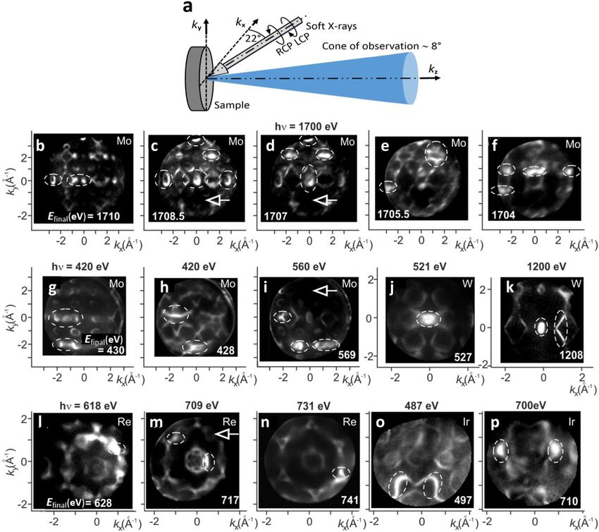
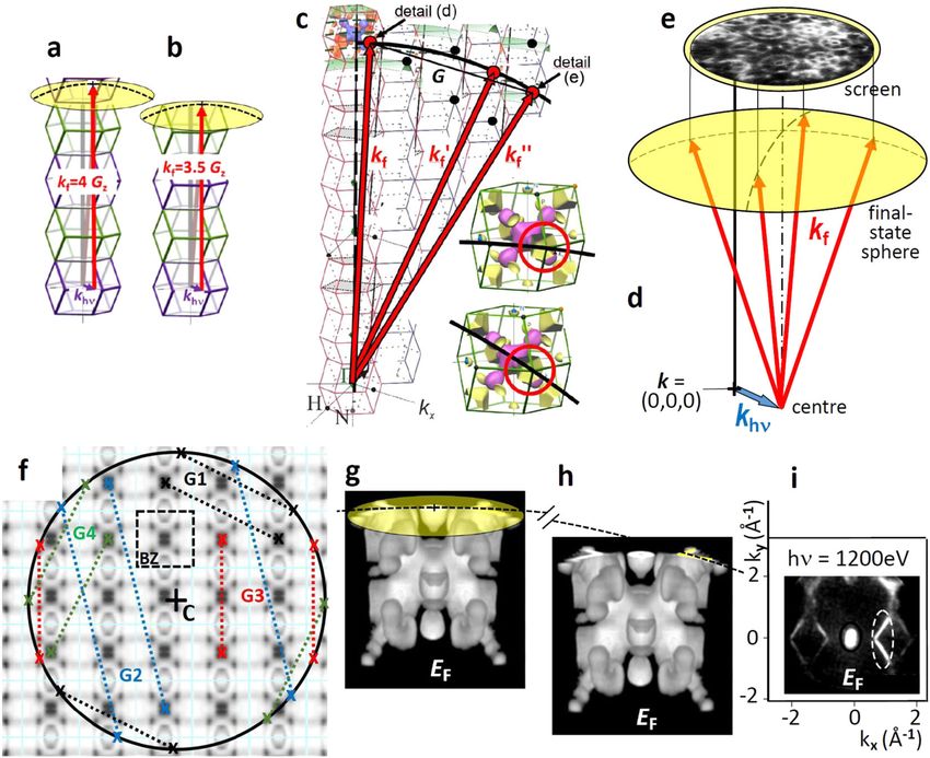
COMMUNICATIONS PHYSICS | https://doi.org/10.1038/s42005-020-0311-9                                                                       ARTICLE

Fig. 1 Overview of valence-band photoelectron-diffraction patterns observed in k-microscopy. a Geometry of the experiment; kx, ky and kz define the
momentum coordinates, RCP and LCP denote righ- and left-circularly polarized light. b–i Momentum distributions taken for Mo(110), j, k for W(110), l–n for
Re(0001), o, p for Ir(111). Photon energies and final-state energies Efinal are denoted in the panels. Areas of local intensity enhancement are marked by
dashed ellipses, local extinctions by arrows. Note the “irregular” patterns of local intensity modulations and the strong variations in (b–f), all taken at
hν = 1700 eV but at five different kinetic energies, separated by increments of only 1.5 eV. The Debye−Waller factor was increased by cooling the samples
to 40 K, energy resolution ∼70 meV.

to a displacement of the centre C of the final-state sphere from                   The umbrella-shaped caps of Fig. 2d–g mark the intersection
the origin k = (0,0,0) by khν. This shift of the sphere is directly            areas of the given isosurface with the final-state sphere, here the
visible in a k-microscope and can be quantified in the observed                 NHP-plane. The band-structure pattern on the curved intersec-
momentum patterns (see, e.g., Fig. 3 in ref. 29). The shift of the             tion area is observed by the momentum microscope. Thanks to
sphere by khν is relatively small at 400 eV but becomes substantial            the 3D-recording scheme of the ToF-microscope, all values of EB
for hard X-rays.                                                               in the energy-range of interest are recorded simultaneously. We
   Figure 2d–g shows 3D-views of four selected energy                          note the analogy with the Ewald-sphere construction in electron
isosurfaces, the Fermi surface and those at EB = 1, 2 and 3 eV.                diffraction: A diffraction spot occurs wherever the Ewald sphere
These surfaces have been determined experimentally as                          intersects a reciprocal lattice point; a photoemission signal occurs
described in ref. 29; see Methods section. Clearly, the shape of               wherever the final-state-sphere (displaced by khν) intersects a
the isosurfaces changes rapidly with binding energy, which is                  band feature in one of the repeated Brillouin zones.
just a full-3D-view of band-dispersion. Bands with negative                       The Ewald sphere does not give information on the intensity of
curvature at EF have hole-character like the N-pocket (growing                 diffraction spots or on systematic extinctions. Likewise, the
with increasing EB, compare (Fig. 2d, f)), positive curvature                  intersection region of the final-state sphere with the periodic
indicates electron-character like the octahedron centred at                    pattern of isosurfaces only shows where band features are visible
the Γ-point that shrinks with increasing binding energy. The                   in principle (obeying energy and momentum conservation). The
background patterns in Fig. 2a, b are (kx, kz)-cuts through the                actual photoemission intensity of a band depends on the matrix
isosurfaces (Fig. 2d, e). In general, khν has an arbitrary direction           element in Eq. (1) that also accounts for the photon polarization
with respect to the reciprocal lattice, and then schemes must                  (symmetry selection rules31).
consider full 3D k-space. The advantage of this representation is
that it immediately shows all the initial k-vectors in a plane                 The 1D case of Bragg-scattering at lattice planes parallel to the
(Fig. 2a, b) or in 3D k-space (Fig. 2d–g) corresponding to a                   surface. The proposed model of VB-XPD describes transitions
certain energy. This is an indispensable ingredient for the                    from itinerant band-states to final-state plane waves (wavevector
description of VB-XPD.                                                         kf) extending over many unit cells, being diffracted at the lattice.

COMMUNICATIONS PHYSICS | (2020)3:45 | https://doi.org/10.1038/s42005-020-0311-9 | www.nature.com/commsphys                                               3
ARTICLE                                                                     COMMUNICATIONS PHYSICS | https://doi.org/10.1038/s42005-020-0311-9

Fig. 2 Momentum-space description of a photo-transition from the valence band. a, b (kx, kz)-schemes describing direct interband transitions into a
quasi-free-electron-like final state band at photon energies between 300 and 400 eV. The axes denote the momentum components kx and kz in units of the
reciprocal lattice vectors G1–10 and G110, respectively, both along the high-symmetry direction ΓN. The plots are to scale for the body-centred cubic metal
Mo. The final-state momentum kf (radius of the final-state sphere) depends on photon energy hν (for fixed binding energy EB) (a) and on EB (for fixed hν)
(b). The centre of the sphere C is displaced from the origin k = (0,0,0) by the vector of the photon momentum khν. The background patterns are cuts
(at ky = 0)) of the periodically repeated measured spectral-density arrays for the Fermi energy EF (a) and for EB = 1 eV (b). Dashed square in (a) marks the
first Brillouin zone (BZ), dark denotes high spectral density. c Brillouin zone of bcc lattice with high-symmetry points; plane ΓNN (yellow) is shown in (a, b).
d–g Measured energy isosurfaces (EB = const. surfaces) at the Fermi energy (d) and at EB = 1, 2 and 3 eV (e−g). The umbrella-shaped top marks the
intersection area with the final-state sphere, which is recorded in a momentum microscope.

This is the concept of Pendry’s model of the “multiple-scattering”               vector Gz = G110 = 2.824 Å−1 for Mo(110). |khν|increases linearly
photoemission final state32–35. In order to stay within the                       with hν, whereas |kf| ∼ hν1/2; hence, at 6 keV we find |khν| = 3.0 Å−1.
description of Fig. 2, we translate Bragg’s law to k-space. For                  For Re(0001) khν⊥ = 1.1 Å−1 is 79% of the reciprocal lattice vector
constructive interference in normal-emission, an integer-multiple                Gz = G0001 = 1.41 Å−1, i.e. the displacement along kz is almost a full
of the photoelectron wavelength λe must coincide with the spa-                   BZ. The interference criterion is that the k-distance between the
cing dz of the atom planes. In backward-scattering the path dif-                 shifted centre of the sphere and the “cap” obeys the rules of Eqs. (3)
ference is twice the spacing dz. With the reciprocal-lattice vector              or (4).
perpendicular to the surface |Gz| = 2π/dz and the final-state
electron momentum |kf| = 2π/λe, we obtain the corresponding                      Valence-band XPD in 3D k-space. Forward scattering is the
relations in k-space:                                                            most easily explained component of VB-XPD. However, it only
            dz ¼ nλe     kf ¼ nGz      forward  scattering ;            ð3Þ     captures a small fraction of all possible scattering processes
                                                                                 involving arbitrary reciprocal lattice vectors G of 3D momentum
                                                                                 space. The generalization of Eqs. (3) and (4) in 3D k-space is the
           dz ¼ n2 λe   kf ¼ n2 Gz    backward  scattering :            ð4Þ     Laue equation:
   Destructive interference occurs when the phase-shift difference                                              kf ¼ k0f  G:                              ð5Þ
     2 π, which can lead to an attenuation of band features as
is 2n1
visible in Fig. 1 (arrows).                                                         Momentum- and energy-balance demand the following five
   The graphical expression of Eqs. (3) and (4) is shown in Fig. 3a,             conditions: (i) the momentum of the electron in the initial
b, respectively. For low photon energies (khν negligible), Eqs. (3)              itinerant state must be included, (ii) the photon momentum
and (4) mean that the final-state-sphere intersects the centre (or                vector khν is transferred to the photoelectron, (iii) the diffraction
the boundary) of a Brillouin-zone. At X-ray energies the shift of                process itself obeys the Laue equation (momentum transfer G),
the final-state sphere by khν causes a deviation from this simple                 (iv) the final-state energy Efinal is preserved (all states lie on the
rule. For the experiments shown below, the angle of incidence is                 same sphere, shifted by khν), (v) the diffraction process leads to
68° from the surface normal; hence, the in-plane and perpendi-                   the same EB-isosurface.
cular components of the shift are |khν| = 0.93|khν| and khν⊥ =                      The k-space-model accounts for these conditions as follows:
0.37|khν|, the latter acting in negative kz-direction. The k-                    Energy isosurfaces like the experimentally determined ones in
microscope records the intensity pattern on a spherical section                  Fig. 2d–g give the complete initial k-distribution (i), which
close to normal emission, sketched as yellow “cap” in Fig. 3a, b.                strongly depends on binding energy. Condition (ii) is fulfilled by a
   At a typical soft-X-ray energy (400 eV), we have |khν| = 0.20 Å−1             rigid shift of the final-state sphere by khν with respect to
and khν⊥ = 0.07 Å−1 which is only 2.4% of the reciprocal lattice                 k = (0,0,0). Final-energy-condition (iv) is fulfilled by plotting the

4                             COMMUNICATIONS PHYSICS | (2020)3:45 | https://doi.org/10.1038/s42005-020-0311-9 | www.nature.com/commsphys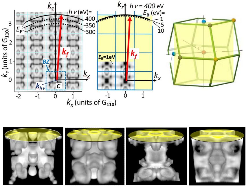
COMMUNICATIONS PHYSICS | https://doi.org/10.1038/s42005-020-0311-9                                                                             ARTICLE

Fig. 3 Momentum-space model of photoelectron diffraction. a, b Direct transitions fulfilling conditions for constructive interference in normal emission
due to forward (a) and backward-scattering (b). c The general case, resembling the Ewald construction, a graphical way to find “spots” where the Laue
condition (kf′ – kf = G) is fulfilled. d Details marking (EB, k)-sectors, where the final-state sphere intersects identical regions in different repeated Brillouin
zones. Vectors kf, kf′ and kf″ are located on the same final-state sphere and reach equivalent points. Reciprocal lattice vectors G give their distances.
e Schematic 3D view showing the vector structure of the transition; length of vector khν exaggerated for clarity. The spherical section is projected onto the
planar screen. f Scheme illustrating that all reciprocal lattice vectors inside of the final-state sphere correspond to two specific (EB, k)-sectors on the
sphere, fulfilling the Laue equation. BZ marks the Brillouin zone, G1−G4 denote reciprocal lattice vectors. g–i Example of the mechanism described in (c),
measured for Mo at EF, hν = 1200 eV and kz close to the border of the Brillouin zone (plane through the high-symmetry points NHP): the V-shaped band on
the right-hand side of the field of view is cut by the final-state sphere in two different Brillouin zones (g) and (h), leading to a strong enhancement of the
observed intensity (i).

photo-transition on a final-state-sphere with radius kf (with the                  lattice vector that is shifted such that it touches the sphere with
centre being shifted according to condition (ii)). Binding-energy                 both ends. Since G is a reciprocal lattice vector, its two ends touch
condition (v) is fulfilled by plotting the isosurface with the correct             identical points of the (reduced) BZ. Each G corresponds to a
EB as periodic pattern in the extended zone scheme, like the two                  specific (EB,k)-region on the shifted sphere where the Laue
cases in Fig. 2a, b.                                                              condition is fulfilled. If a band feature runs through such a region,
   The remaining task is to fulfil condition (iii). It means that we               its intensity is enhanced by VB-XPD.
search for intersection points of the final-state sphere for a given                  Figure 3g–i shows an example for Mo at hν = 1200 eV, for the
EB with equivalent k-points in different repeated BZs, fulfilling                  Fermi energy and a kz-section through the NHP-plane of the BZ
the Laue equation. Such cases are illustrated in Fig. 3c, where the               (Fig. 2c). The right V-shaped region on top of the isosurface is
vectors kf′ and kf″ reach the same band feature as vector kf, but in              crossed by the final-state-sphere in two different BZs (Fig. 3g, h).
different BZs. The red circles in insets of Fig. 3d mark the (EB, k)-             In turn, the intensity of this feature in the measured momentum
regions, where the final-state sphere intersects such identical                    pattern is enhanced by VB-XPD (dashed ellipse in Fig. 3i). Here it
points. Their distances are given by certain reciprocal lattice                   becomes clear why the VB-XPD patterns look irregular and do
vectors G. In complete analogy to the Ewald construction, energy                  not reflect the lattice symmetry: The shift of the final-state sphere
conservation demands that both ends of G must lie on the final-                    by khν breaks the symmetry. For example, in the case of Fig. 3f,
state sphere, which defines the (EB, k)-region where the intensity                 the diffraction condition on the left and right side (red line G3) is
is enhanced by VB-XPD. The scheme in Fig. 3e illustrates the 3D-                  fulfilled for different regions of BZ.
nature of the momentum-transfer scenario. The planar detector-                       With respect to the “continuum” of kinetic energies the
screen captures the projection of the curved cap.                                 situation resembles Laue diffraction using a broad-band X-ray
   All vectors G, which are completely inside of the final-state                   beam. However, the band dispersion poses additional constr-
sphere, fulfil the diffraction condition on opposite sides of the                  aints that—together with the broken symmetry—make the
circle (Fig. 3f) and at a multitude of positions on the sphere. Each              situation quite complex. “k-space movies” (Supplementary
of the dotted coloured lines G1–G4 represent a certain reciprocal                 Videos 1–5) illustrate this puzzling behaviour. Most important

COMMUNICATIONS PHYSICS | (2020)3:45 | https://doi.org/10.1038/s42005-020-0311-9 | www.nature.com/commsphys                                                     5
ARTICLE                                                                       COMMUNICATIONS PHYSICS | https://doi.org/10.1038/s42005-020-0311-9

Fig. 4 Pronounced forward scattering in normal emission for valence-band photoelectrons from the Mo(110) surface at hν = 460 eV. a–c Tomographic-
like kx − ky momentum sections through the region of maximum intensity enhancement, visible in the isosurfaces at the Fermi energy (a), a binding energy
of EB = 1.8 eV (b) and in the EB − ky section (c) along the dashed line in (b). d, e EB – kx and EB – ky sections in regions away from the interference condition,
showing a much lower and more evenly distributed intensity; sections along the dashed lines in (a). f Integrated photoemission-intensity versus binding-
energy taken from the dotted rectangle in (b), illustrating the intensity enhancement. g Scaled transition scheme for Mo(110) at 460 eV in the kz−kx plane;
the final-state sphere intersects the centre of the fourth repeated Brillouin zone (diffraction condition kf = 4Gz).

are the different roles of the two relevant energies, Efinal and EB.                  This type of intensity enhancement occurs even in the VUV-
The former defines the wavelength of the photoelectron, which                      range; see example for Re in Fig. 5. An intense spot of
governs diffraction dynamics. The latter defines the relevant                      constructive interference appears in the centre of the kx−ky
isosurface of the spectral function ρ(EB, k) which is strongly                    images (Fig. 5a–c). The EB-vs.-kx sections (Fig. 5d–f) reveal that
energy dependent, giving rise to the strong diffraction modulation                the enhancement is restricted to a small energy range of
on the eV-scale (Fig. 1a–e). In CL-XPD EB is fixed and there is no                 ∼200 meV width. When varying the photon energy, this spot
E-vs.-k dispersion; hence, only one energy- and one momentum-                     shifts in binding energy by the same amount, as revealed by the
condition exist.                                                                  intensity profiles (Fig. 5g–i). Clearly, the constructive interference
                                                                                  stays at fixed Efinal, because this energy is relevant for the
                                                                                  diffraction dynamics. The change of the enhancement from band
Experimental results for near-normal emission. Figure 4 shows                     to band excludes a matrix element effect. In the vicinity of EF
a typical example for strong intensity enhancement around the                     there is a total bandgap at the Γ-point, so we cannot follow
centre of the kx−ky distribution (Fig. 4a, b) with maximum                        the trend up to the Fermi energy. Given the lattice constants of
intensity at EB ∼ 1.8 eV, also visible in the EB–ky section (Fig. 4c).            Re and khν ≈ 0, the centre of the second BZ is at kz = 2G0001 =
In comparison, EB–kx and EB–ky sections away from normal                          2.82 Å−1 which agrees approximately with the given final state
emission show a much lower intensity and more homogeneous                         momentum. However, the final state is no longer free-electron-
intensity distributions along the bands (Fig. 4d, e). Figure 4f                   like, deviations from parabolic dispersion can occur and flat
reveals the spectral dependence of the intensity-enhancement,                     unoccupied d-bands can serve as additional final states.
integrated over the rectangular area marked in Fig. 4b. The dif-
fuse background shows horizontal “stripes” of enhanced intensity                  Experimental results of VB-XPD for arbitrary reciprocal lattice
in Fig. 4d, e, which are a fingerprint of quasi-elastic thermal-                   vectors. The—at first sight puzzling—multitude of irregularly
diffuse scattering. Their energy position (here ∼1.8 and 3.3 eV)                  distributed regions of strong intensity enhancement observed for
corresponds to maxima in the matrix-element weighted density of                   all materials studied so far (overview in Fig. 1) reflects the general
states (MEWDOS) as discussed in refs. 19,21,23,30. The MEWDOS                     case of Fig. 3c–i. Figure 6 shows an analysis for Mo(110) at hν =
stripes appear inhomogeneous, which might point on a direc-                       1700 eV. With kf = 21.17 Å−1 this transition leads to the eighth
tional dependence of the diffuse scattering effect.                               repeated BZ; khν = 0.86 Å−1 shifts the sphere by 45% of the BZ
   We analyse the transition by the quantitative scheme in                        radius. The diameter of the k-field of view in Fig. 6a is ∼6 Å−1;
Fig. 4g, with Gz = Ghkl = G110 = 2.824 Å−1 and khν = 0.23 Å−1                     hence, the first and four next BZs are visible. The kx−ky and
(khν⊥ = 0.09 Å−1; |khν| = 0.21 Å−1). The intensity enhancement                    EB−kx cuts (Fig. 6a, b) show pronounced intensity enhancement
confirms Eq. (3) with kf = 4G110, shifted by the small value of                    in a small region within 200 meV from the Fermi energy, whereas
khν⊥ away from the Γ-point of the fourth repeated BZ. Such                        no enhancement is visible in the EB−ky cut (Fig. 6c). Quantitative
measurements provide a metric in k-space for the determination                    analysis by the transition scheme (Fig. 6d) reveals that the sphere
of the centres and boundaries of repeated BZs and for the                         crosses the identical feature for kf′ – kf = G−1 1 0 (see details in
empirical quantities meff and V0* in Eq. (2). Precise measurement                 Fig. 6e) and kf″ – kf = G−2 14 0. Both constructive interference
of the energies of diffraction enhancement for two high-                          conditions lead to the observed intensity enhancement (dashed
symmetry planes can yield both parameters. From the single                        ellipses in Fig. 6a, b).
measurement of Fig. 4, we derive meff = 1.03 me (1.04 me)                            In the terminology of a diffraction experiment, the low- and
assuming V0* = 10 eV (6 eV). Here the resulting meff depends                      high-index cases G−1 1 0 and G−2 14 0 belong to the zero-order
only weakly on the assumed value of V0* .                                         and a higher-order Laue-zone, respectively. Due to the forward

6                             COMMUNICATIONS PHYSICS | (2020)3:45 | https://doi.org/10.1038/s42005-020-0311-9 | www.nature.com/commsphys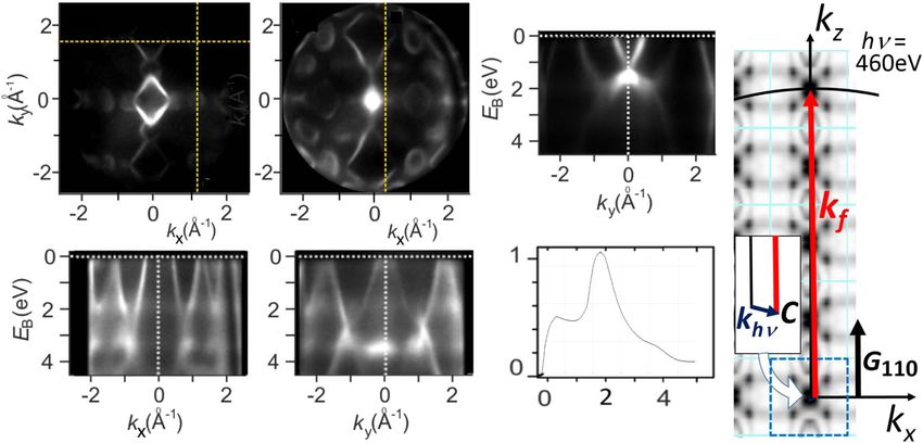
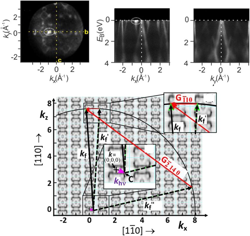
COMMUNICATIONS PHYSICS | https://doi.org/10.1038/s42005-020-0311-9                                                                               ARTICLE

Fig. 5 Photon-energy dependence of valence-band photoelectron diffraction for Re(0001) between hν = 15 and 16 eV. a–c Momentum distributions in
the kx − ky plane; d–f corresponding sections of binding energy EB vs. momentum component kx along the dashed lines in (a–c). g–i Binding-energy profiles
of the intensities in the areas marked by rectangles in (a–c). The interference condition shifts with photon energy; steps of 0.5 eV correspond to
momentum steps of only 0.04 Å−1 along kz.

Fig. 6 Analysis of valence-band photoelectron diffraction for the Mo(110) surface at hν = 1700 eV. a Momentum distribution in the kx−ky momentum
plane showing an intensity enhancement in a small local region (dashed ellipse). b Section of binding energy EB vs. momentum component kx along the
dashed line in (a) revealing the energetic localization close to the Fermi energy EF. c EB vs. ky section showing that there is no intensity enhancement in this
plane. d Quantitative analysis yielding that the final-state sphere runs through the eight repeated Brillouin zone along kz and crosses the identical feature
for the Laue conditions kf' – kf = G−1 1 0 (details in (e)) and kf″ – kf = G−2 14 0. Vectors G are labelled by the Miller indices; the high index of 14 results from
our choice of the kx- and ky-axes along crystallographic directions [110] and [1 –1 0]. The photon momentum khv causes a strong shift of the centre C of the
sphere (details in (f)). The background pattern is the periodically repeated measured 4D array, cut at EF and ky = 0 (dark is high spectral density). Full data
array for 1700 eV; see Supplementary Videos 1 and 2.

COMMUNICATIONS PHYSICS | (2020)3:45 | https://doi.org/10.1038/s42005-020-0311-9 | www.nature.com/commsphys                                                        7
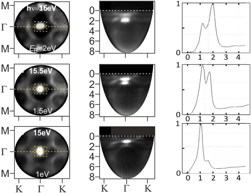
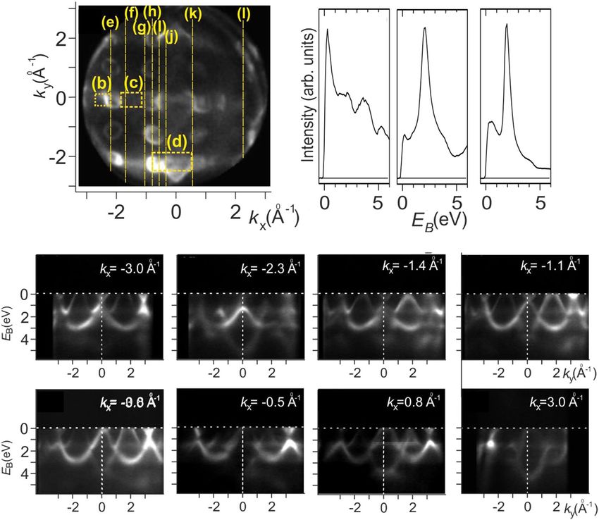
ARTICLE                                                                   COMMUNICATIONS PHYSICS | https://doi.org/10.1038/s42005-020-0311-9

Fig. 7 Energy- and momentum-dependence of valence-band photoelectron diffraction for Mo(110) at a photon energy of 400 eV. a (kx−ky) momentum
section at the Fermi energy EF. b–d Intensity profiles revealing resonance-like intensity enhancements in the areas marked by rectangles in (a). e–l Binding
energy EB vs. momentum ky sections at eight values of momentum kx between −3 Å−1 and +3 Å−1 (along the dashed lines in (a)), revealing the variation of
local intensity enhancements with energy and momentum. Although the photon momentum is rather small at 400 eV, the shift of the final-state sphere is
sufficient to cause a striking left−right asymmetry in the patterns. Full data arrays of 400, 420 and 440 eV; see Supplementary Videos 3−5.

characteristic of scattering at keV energies, the diffracted intensity         magnitude brighter as the surrounding bands. The horizontal
is larger for the smaller scattering angle, i.e. the lower Miller              stripes with enhanced brightness in Fig. 7a confirm the 3D-
index. Note that here we consider only a planar cut through one                generalization of the graphical model in Fig. 3. For instance, in
quadrant. There will be many more such conditions when the full                3D the reciprocal lattice vector G3 responsible for the red lines in
final-state sphere in 3D k-space is considered.                                 Fig. 3f yields a full cylinder touching the final-state sphere along
   The sequence for Mo at hν = 400 eV in Fig. 7 captures some                  two rings.
snapshots. The way how the positions for constructive inter-
ference “travel” through (EB, k)-space is best visible in                      Coexistence of Laue- and Kikuchi-type VB-XPD in the hard X-
Supplementary Videos 3–5. The cut at EF (Fig. 7a) and the                      ray range. At hard X-ray energies, a new type of diffraction
intensity profiles (Fig. 7b–d), taken in the rectangular areas                  signature appears; experiments were performed at beamline P22
marked in Fig. 7a, reveal a number of regions with locally                     of PETRA III. Results for Re at Efinal = 3.4 and 6 keV (Fig. 8)
enhanced intensities. Electron- and hole-pockets appear as oval                reveal that a significant background is superimposed on the as-
features (Fig. 7a) with inward or outward dispersion; see cuts in              measured valence-band k-distributions. This background is
Fig. 7e–l, taken along the dashed lines in Fig. 7a. Enhanced                   higher than for Mo at 1.7 keV (Fig. 6a). At 3.4 keV (Fig. 8a–h)
intensities appear mostly in the second BZ at negative kx and ky               valence-bands are visible as circles, originating from an electron-
values and show almost “resonance-like” VB-XPD enhancements.                   like tube centred at the A-point, and ellipses from elongated hole-
   Proving that the interference stays fixed on the Efinal-scale like            pockets at the M-points. A lattice model is shown in Fig. 8i and
in Fig. 5 would require prohibitively long acquisition sequences in            the BZ with its high-symmetry points are defined in Fig. 8j. At
0.5 eV photon-energy steps. In Figs. 4 and 6, high intensity in                Efinal = 6 keV (Fig. 8k–m) the background is even higher, the VB-
comparison with neighbouring bands and sudden intensity jumps                  pattern looks irregular and band-structure features are hardly
along a band are used as criterion for VB-XPD. The enhancement                 discernible. The most eye-catching features are pronounced dark
in the electron ball (Fig. 7e) at the lower left rim of Fig. 7a shows a        spots (marked by crosses), two bright regions at the upper left rim
rather sharp cutoff at a binding energy of ∼2 eV. Figure 7f shows              (dashed ellipses) and a bright X-shaped feature (centre marked by
the enhanced maximum of a band that stays well below EF.                       a circled cross). Here the field-of-view (∼12 Å−1) comprises 19
Sequence Fig. 7g–j shows how the interference condition crosses                BZs: the central one, and two rings with 6 and 12 BZs centred
the equivalent k-space object in the BZ at the bottom of Fig. 7a.              around it. On this large momentum scale, we observe something
The enhancement exhibits a characteristic “fine structure”.                     new. The as-measured VB-patterns (Fig. 8a, k) are modulated by
Figure 7k extends the analysis to the other side of the bottom                 pronounced long-range structures.
BZ and finally Fig. 7l returns to the object of Fig. 7e, but at                    The key of understanding the long-range modulations lies in
opposite kx and ky. The small spot in Fig. 7l appears an order of              the comparison of as-measured VB k-patterns with CL-XPD

8                            COMMUNICATIONS PHYSICS | (2020)3:45 | https://doi.org/10.1038/s42005-020-0311-9 | www.nature.com/commsphys
COMMUNICATIONS PHYSICS | https://doi.org/10.1038/s42005-020-0311-9                                                                            ARTICLE

Fig. 8 Two types of photoelectron diffraction for Rhenium (0001) in the hard X-ray range. a As-measured valence-band (VB) (kx, ky) momentum
pattern at the final-state energy Efinal = 3.4 keV; crosses mark signatures of Kikuchi diffraction. b Re 4f7/2 core-level X-ray photoelectron diffraction (XPD)
pattern taken at the same final-state energy and identical settings of the microscope. Crosses and ellipses mark the same features as in (a), the circled
cross marks the centre of symmetry ([0001]-direction) and the double arrow marks the principal Kikuchi band (width 2|G11–20|). c Ratio image of the
valence-band pattern (VB) and the core-level diffractogram (4f7/2 XPD) showing the valence-band structure with eliminated diffraction modulation. Pluses
mark the centres of the Brillouin zones. d–f Binding energy EB vs. momentum ky, kx sections of valence-band and 4f core-level signals. Dashed ellipses in
(d, e) mark signatures of Laue-type diffraction. g, h Time-of-flight spectra for the Re 4f core level and valence band, respectively. The bars denote the
energy regions integrated for momentum patterns (a) and (b). i Real-space model illustrating the origin of the principal Kikuchi band marked in (b) as
double arrow. j Brillouin zone of the hexagonal-close-packed Re lattice. k–m Same as (a–c) but for 6.0 keV; crosses and dashed ellipses mark intensity-
modulations by Kikuchi diffraction. Sections (c) and (m) run through different planes of the Brillouin zone (dashed and dotted lines in (j)). The lateral shifts
of the valence-band pattern with respect to the [0001]-direction (difference between circled plusses and circled crosses in (c) and (m)) reflect the transfer
of photon momentum khν to the valence-band photoelectrons.

patterns26. Figure 8b, l shows core-level diffractograms taken                      The Re4f7/2 XPD-pattern at Efinal = 6 keV (Fig. 8l) exhibits a
at the Re4f7/2 signal (Fig. 8g). The photon energy was                           rich fine structure due to the shorter wavelength of the outgoing
increased by 41 eV in order to shift the 4f7/2-signal to exactly                 photoelectron and the larger inelastic mean-free path36. It also
the same final-state energy as the valence patterns; see                          shows a system of Kikuchi bands, dark spots (marked by crosses)
spectra in Fig. 8g, h. All other settings of the microscope                      and bright regions (dashed ellipses). The centre of symmetry
were kept fixed so that the k-scales stay identical, for later                    (k = 0) shows a bright X-shaped feature (centre marked by a
correction. At Efinal = 3.4 keV the 4f7/2-XPD-pattern (Fig. 8b)                   circled cross). All these characteristic features are visible in the
shows a system of Kikuchi bands crossing under 120°, whose                       measured valence-band momentum-image (Fig. 8k) as well. The
intersection region is visible as a bright hexagon centred at                    model in Fig. 8i shows the lattice planes with distance d11–20,
the [0001]-direction (circled cross). Position and size of the                   leading to the outgoing rays forming the Kikuchi band (width
hexagon and dark areas in the XPD-pattern (Fig. 8b) agree                        2G11–20, see double arrows in Fig. 8b, l) in the k-microscope
with the structure imprinted on the valence-band-pattern                         images. The centre of the images was shifted downwards in order
in Fig. 8a.                                                                      to reach a larger radius in the upper part.

COMMUNICATIONS PHYSICS | (2020)3:45 | https://doi.org/10.1038/s42005-020-0311-9 | www.nature.com/commsphys                                                    9
ARTICLE                                                                COMMUNICATIONS PHYSICS | https://doi.org/10.1038/s42005-020-0311-9

   Following ref. 26, we eliminate the Kikuchi-modulation by                (ii) In the hard-X-ray range another mechanism, Kikuchi-
multiplicative correction, yielding the pixel-by-pixel ratio of the              diffraction, contributes to VB-XPD and becomes dominant
as-measured VB-patterns (Fig. 8a, k) and the core-level                          at energies of several keV. The signatures of this effect are
diffractograms (Fig. 8b, l). In the ratio images (Fig. 8c, m) the                the long-range modulation of the VB-patterns by Kikuchi-
diffraction modulation is largely eliminated and the true valence-               bands and -lines and the fact that the modulation patterns
band features are clearly visible. The two VB-patterns are                       reflect the full lattice symmetry. Different from the
different because at 6 keV the final-state sphere runs through                    almost resonance-like Laue-type intensity modulation, the
the ΓMK-plane and at 3.4 keV close to the AHL-plane of the BZ                    Kikuchi-modulation acts on the entire field of view and is
(indicated by the dotted and dashed sectional planes in the BZ                   “extrinsic” to the photoemission process, without participa-
(Fig. 8j), respectively). The increased noise in Fig. 8m reflects the             tion of photon momentum.
dramatic drop in cross section with increasing energy26,37. Close          (iii) The quasi-elastic background underlying the VB-patterns
inspection reveals that Kikuchi diffraction acts on both the                     also shows a pronounced Kikuchi-type diffraction signature,
underlying background signal and the band features themselves.                   characterized by a strong intensity increase with increa-
Remarkably, after the division regions of local intensity                        sing final-state energy and temperature (Fig. 4 of ref. 26).
enhancement due to Laue-type diffraction are still present                       Although overlooked in the past, Kikuchi patterns in the
(marked by dashed ellipses in Fig. 8d, e).                                       background are not too surprising because such processes
   The rigid shift of the entire VB k-distribution by the photon                 are also responsible for Kikuchi diffraction in scanning
momentum is clearly visible in the difference between the centre                 and transmission electron microscopy (SEM/TEM)41–43
of the Kikuchi patterns and the centre of the VB-patterns                        as discussed in detail by Wang44. Unlike SEM/TEM this
(marked by circled cross and circled plus in Fig. 8c, m,                         background extends over a continuous energy band
respectively). The Kikuchi patterns are symmetric to the crystal-                (typically more than 10 eV) in photoemission. Stocha-
lographic [0001]-direction at k‖ = 0 (b, l). The VB-patterns are                 stic quasi-elastic scattering events of VB-photoelectrons
defined on the k-scale of the band states (kx, ky), which refers to               (mostly thermally induced) cause a localization of the
the centre (Γ-point) of the band structure (Fig. 8c, m). The                     scattered electron. The coherence with the final-state-wave-
transfer of khν shifts the origin of the (kx, ky)-scale (circled                 field is lost, but the scattered wave is coherent again and
crosses) significantly away from the [0001]-direction (circled                    experiences Kikuchi-diffraction at the lattice. Unlike Laue-
plusses). The curvature of the final-state sphere is clearly visible              type diffraction, this mechanism is “extrinsic” to the VB-
for such large k-fields. The intersection contour of the sphere with              photoemission process, since initial coherence is lost and khν
the periodic patterns of BZs runs through different kz-values, as                is not involved. We found Kikuchi-modulations imprinted
explained in Figs. 2a, b and 3c. In turn, the patterns in Fig. 8c, m             on the valence-band k-distributions and their background
are not strictly periodic because at the rim the kz-values are                   for all single-crystalline samples studied so far (W, Mo, Re,
smaller than in the centre. The photon polarization (p-polarized                 Ir, graphite, Si, GaAs, SrTiO3, NbSe2 and other transition-
with electric vector tilted by 22° against the surface normal)                   metal dichalcogenides).
causes asymmetries in the photoemission signal31,38, which are             (iv) The fourth category of XPD-signature, well-known from
still significant in the HAXPES range39.                                          previous work7,8,16,17, are the Kikuchi-patterns in core-level
                                                                                 XPD, i.e. for monoenergetic energy distributions. Recording
Discussion                                                                       such patterns is most important for the correction
We categorize the complex appearance of photoelectron diffrac-                   algorithm described in ref. 26. Comprehensive work in
tion into four different classes:                                                the field of electron microscopy (SEM and TEM)
                                                                                 validated Kikuchi-diffraction as powerful tool for structural
 (i) Strong local intensity modulations (up to a factor of 5 in                  analysis41–44.
     both directions) occur in the observed VB-patterns in all
     spectral ranges studied (15 eV–7 keV). The signatures of this            The long-range-modulations on the VB-patterns need addi-
     mechanism are its strong confinement in (EB, k) parameter-             tional discussion. If a k-randomizing scattering event (like in
     space to intervals down to ∼200 meV and ∼0.03 Å−1                     the classical Kikuchi-process) were involved, the bands in the
     and its lack of symmetry and any visible systematics. A               intensity-enhanced regions would not stay sharp. Apparently,
     graphical model based on Umklapp processes on the final-               the high-energy Bloch waves of the photoelectrons excited in the
     state energy isosphere in k-space explains this type of XPD-          direct transition (with well-defined kf) experience Bragg-
     modulation and its extremely rapid variation with energy              reflection at sets of lattice planes. This can be considered as
     and momentum. The missing symmetry in VB-XPD                          “half” a Kikuchi-process (with missing initial scattering-step).
     patterns reflects the transfer of photon momentum khν to               This imprinted pattern has the same orientation, symmetry
     the photoelectron, causing a rigid shift of the final-state            and metric as the classical Kikuchi-pattern imprinted on the
     sphere in k-space. We adopt the term Laue-type diffraction            background.
     because VB-XPD deals with an energy band, similar to                     At this point we should have a look at the status of photo-
     Laue-diffraction with an X-ray continuum40. This mechan-              emission theories. The existing code for one-step photoemission
     ism is “intrinsic” to the photoemission process, as the               calculations yields excellent agreement concerning band features
     transfer of khν enters into the selection of the electron-wave-       observed with soft and hard X-rays30; its extension towards
     vector of the final state. It has first been introduced by              calculating VB-XPD by including photon-momentum and Laue-
     Pendry et al.32–35 in terms of the multiple-scattering final           type Umklapp-processes is in progress. Measured CL-XPD
     state (“time-reversed LEED-state”). The number of (EB, k)-            patterns show excellent agreement with calculations using the
     regions in which the Laue condition is fulfilled increases             Bloch-wave model between hν = 2.8–7.2 keV45. This opens a new
     with the number of BZs on the surface of the final-state               avenue towards in situ structural analysis, simultaneously with
     energy isosphere. For hν = 50, 400, 1700 and 6000 eV, the             VB-mapping. First results identifying two different sites of Te-
     numbers of BZs on the surface of the sphere are about 25,             atoms in a Si crystal, tracking an incommensurate−commensu-
     170, 708 and 2488, respectively (taking the parameters for            rate phase transition in TaS2 or first time-resolved pump−probe
     Mo from Fig. 2).                                                      experiments46 give a glance on the potential of full-field imaging

10                        COMMUNICATIONS PHYSICS | (2020)3:45 | https://doi.org/10.1038/s42005-020-0311-9 | www.nature.com/commsphys
COMMUNICATIONS PHYSICS | https://doi.org/10.1038/s42005-020-0311-9 ARTICLE
CL-XPD. New approaches like adapting a Bloch-wave model to formed, which is a key feature for low-energy electron microscopy55. The sub-
VB-XPD might help to understand the experimental observations sequent zoom lenses project this k-image on the entrance plane of the image
detector, in our setup a delay-line detector (DLD). For each electron the time of
and underlying processes more quantitatively. In generalization flight in the low-energy drift section of the microscope column is recorded,
of the analysis of Fig. 6, the appearance of VB-XPD patterns exploiting the time structure of the synchrotron radiation. ToF is converted into
could be predicted by feeding measured 4D spectral-density kinetic energy and calibrated at the Fermi edge yielding the binding energy EB. A
functions into a suitable computer program that would auto- size-selectable field aperture in an intermediate real-space image plane facilitates
matically find all possible diffraction conditions for a given the selection of well-defined source areas on the sample surface with diameters
down to the μm-range. The imaged k-field of view has a linear momentum scale up
photon energy. to a diameter of ∼7 Å−1; for larger fields a significant field curvature appears
We can consider the Laue- and Kikuchi-scenario as two (a well-known effect for wide-angle lenses). The deterministic part of the Coulomb
diffraction-branches with fundamentally different characteristics: interaction between the valence-band photoelectrons and the large number of
The Laue-type Umklapp-process is intrinsic and happens on the secondary electrons was corrected employing the concept described in ref. 56.
For the investigation of the long-range Kikuchi-type diffraction patterns taken
final-state energy isosphere, which is shifted in k-space by the with hard X-rays from beamline P22 (results in Fig. 8), we used a ToF k-
photon momentum khν. This diffraction branch can only be microscope with new optics, optimized for high initial kinetic energies up to
understood in a rigorous k-space treatment as presented in this >8 keV. Its novel type of objective lens can image large k-field diameters up to
paper. The Kikuchi signature, however, is extrinsic and governed ∼22 Å−1, comprising many Brillouin zones in parallel. The small photon footprint
of ∼20 × 30 μm2 causes a large depth of focus of the k-images. In turn, large energy
by the orientation of the lattice planes and thus the modulation ranges are imaged with good focus in a single exposure. This instrument uses a
reflects the lattice symmetry. For Re at a temperature of 30 K and DLD with 80 mm active area. The DLDs in both setups record count rates up to
3.4 keV the relative weight of the Kikuchi-branch is comparable ∼5 MHz at a spatial resolution of ∼80 μm and a time resolution of 180 ps, yielding
to the Laue-branch, whereas at 6 keV the Kikuchi-branch is lar- >1000 resolvable time slices at the given pulse period of 192 ns for the 40-bunch
filling pattern of PETRA III. The measured energy resolution of the combination of
gely dominating. Since the Debye−Waller factor shows an DLD and imaging ToF-spectrometer (0.9 m long) at a drift energy of 10 eV is
exponential dependence on temperature26, this ratio varies with 17 meV, measured in a low-energy experiment using laser excitation.
dropping temperature in favour of the Laue-branch. The coex-
istence of several XPD-branches and the role of khν inducing the Data recording. Valence-band 3D data arrays I(EB, kx, ky) are recorded with
dramatic loss of symmetry go beyond Pendry’s multiple- acquisition times of typically 20 min at P04 and about 1 h at P22. The acquisition of
scattering final-state Ansatz and theoretical ab-initio treatment core-level XPD patterns like in Fig. 8 is faster. The two momentum coordinates (kx,
appears quite complex. ky) are observed by full-field k-imaging and many binding energies EB are taken
simultaneously in a single exposure by recording the time coordinate (referenced to
ARPES and k-microscopy in the X-ray range are rapidly the photon pulse) of each individual counting event in the DLD. The sample is
gaining importance and excellent momentum and energy- mounted on a He-cooled hexapod manipulator for precise six-axis adjustment.
resolution is achieved (e.g. ∼60 meV at 6 keV47). However, the Most data have been recorded at sample temperatures around 30 K. The circularly
band maps observed at a given photon energy are strongly polarized (at P04) or p-polarized photon beam (at P22) impinges at 22° with
modulated by VB-XPD. The same is true for the linear and cir- respect to the sample surface (Fig. 1a).
The high parallelization of data acquisition and the high brilliance of the
cular dichroism48,49 and the spin-polarization texture50. If dis- beamlines compensate for the strong decrease of photoemission cross-section with
regarded, this substantial influence of photoelectron diffraction increasing photon energy towards the hard X-ray range (Fig. 1 in ref. 26). Count-
on the observed band features including their dichroism and spin rates exceeding 106 counts per second in an interval of ∼15 eV are obtained in the
polarization can cause misinterpretations with respect to the valence range at all photon energies used. When recording core-level signals, a
proper attenuation of the X-ray beam was necessary in order to avoid excessive
spectral function and its spin-character. count rates.
It is worthwhile to consider the momentum- and energy-resolution at high
energies in the several-keV range. The band features appear sharp up to the
Methods maximum photon energy used (here 6 keV). With increasing binding energy the
Beamlines. The experiments have been carried out at two beamlines (P04 and P22) reduced lifetime of the photo-hole leads to a broadening of the band features. At EF
of the storage ring PETRA III at DESY in Hamburg and a VUV-beamline at BESSY this broadening vanishes but at EB ∼ 3 eV the hole lifetime is 12.5 fs corresponding
II, Berlin. The hard X-ray measurements (Fig. 8) have been performed at beamline to 50 meV, being in the order of the overall instrumental resolution mentioned
P22, which belongs to the beamlines with the highest brilliance worldwide in an above. We do not observe a final-state broadening or smearing of kz-resolution
energy range from 2.4 to 15 keV51. Conditions for the present experiments were with increasing energy. This is most likely connected with the fact that the
2 × 10¹³ photons/s at 4–6 keV in a spot of about 15 × 20 μm2. Using the Si(111) reciprocal space is a periodic pattern of BZs. Thus, except for the matrix elements
double-crystal monochromator the bandwidth varies from 350 meV in the 3 keV that depend on photon energy, these patterns should be equivalent for direct
range to 500 meV at >6 keV. The Si(311) monochromator crystal yields a three transitions leading to low- or high-energy repeated BZs along kz. The “transfer-
times smaller bandwidth. At 5.3 keV we measured 450 and 155 meV for the Si(111) width” argument is even in favour of high kz-resolution at very high energies,
and (311) crystals, respectively, and at 5.977 keV an FWHM of 62 meV using the Si because more and more unit cells contribute to the observed signal. Given the
(333) crystal47. The resolving power for the (333)-crystal is >105. present experimental conditions we did not expect to observe recoil effects24; this
For the soft X-ray measurements (Figs. 1–4, 6 and 7) we used beamline P04 of issue is subject of ongoing experiments.
PETRA III52 providing photons in the spectral range between 260 eV and 2 keV in
a spot ofARTICLE COMMUNICATIONS PHYSICS | https://doi.org/10.1038/s42005-020-0311-9
vE(k) is oriented perpendicular to the corresponding isosurface and is given by the 21. Osterwalder, J., Greber, T., Aebi, P., Fasel, R. & Schlapbach, L. Final-state
gradient of E(k) in k-space at the energy of interest. scattering in angle-resolved ultraviolet photoemission from copper. Phys. Rev.
B 53, 10209 (1996).
Sample preparation. The refractory metal crystals W, Mo, Re, Ir were cleaned by 22. Sondergaard, Ch et al. Symmetry-resolved density of states from valence band
repeated cycles of heating in oxygen followed by desorption of the surface oxide by photoelectron diffraction. Phys. Rev. B 64, 245110 (2001).
a flash at high temperature. The base pressure during the experiment was 4 × 23. Krüger, P., Da Pieve, F. & Osterwalder, J. Real-space multiple scattering
10−10 mbar. Prior to the soft X-ray measurements the surface quality was verified method for angle-resolved photoemission and valence-band photoelectron
by LEED. Layered samples like graphite and the transition-metal dichalcogenides diffraction and its application to Cu(111). Phys. Rev. B 83, 115437 (2011).
were cleaved in UHV prior to transfer to the microscope chamber. No traces of 24. Kayanuma, Y. in Hard X-ray Photoelectron Spectroscopy (HAXPES), Springer
impurities, as judged, for example, by C 1s and O 1s spectra, were present in the Series in Surface Sciences Ch. 8, Vol. 59 (Springer International Publishing,
spectra. Since it is operated in the shielding hutch at P22 all lens voltages, the data Switzerland, 2016).
acquisition system and all mechanical adjustment parameters (hexapod, frame 25. Braun, J., Minár, J. & Ebert, H. Correlation, temperature and disorder: recent
position, apertures of the microscope) are fully remote controlled. developments in the one-step description of angle-resolved photoemission.
Phys. Rep. 740, 1–34 (2018) and references therein.
26. Babenkov, S. et al. High-accuracy bulk electronic structure mapping:
Data availability momentum-resolved hard X-ray photoelectron spectroscopy with eliminated
The data that support the findings of this study are available from the corresponding diffraction effects. Comms. Phys. 2, 107 (2019).
author upon reasonable request. 27. Hüfner, S. Photoelectron Spectroscopy─Principles and Applications (Springer,
Berlin, 2003).
Received: 23 July 2019; Accepted: 10 February 2020; 28. Reinert, F. & Hüfner, S. Photoemission spectroscopy—from early days to
recent applications. N. J. Phys. 7, 97 (2005).
29. Medjanik, K. et al. Direct 3D mapping of the Fermi surface and Fermi velocity.
Nat. Mat. 16, 615 (2017).
30. Gray, A. X. et al. Probing bulk electronic structure with hard X-ray angle-
resolved photoemission. Nat. Mat. 10, 759 (2011).
31. Plummer, E. W. & Eberhardt, W. in Advance in Chemical Physics Vol. XLIX
References (eds Prigogine, I. & Rice, S. A.), 533−656 (John Wiley, 1982).
1. Fadley, C. S. & Nemsak, S. Some future perspectives in soft- and hard-X-ray 32. Pendry, J. B. Theory of photoemission. Surf. Sci. 57, 679–705 (1976).
photoemission. J. Electron. Spectrosc. Relat. Phenom. 199, 408–423 (2014). 33. Pendry, J. B. & Hopkinson, J. F. L. Theory of photoemmission. J. Phys.
2. Strocov, V. N. et al. k-resolved electronic structure of buried heterostructure Colloques 39, C4-142–C4-148 (1978).
and impurity systems by soft-X-ray ARPES. J. Electron Spectrosc. Relat. 34. Hopkinson, J. F. L., Pendry, J. B. & Titterington, D. J. Calculation of
Phenom. 236, 1–8 (2019) photoemission spectra for surfaces of solids. Comput. Phys. Commun. 19,
3. Woicik, J. C. (ed.) Hard X-ray Photoelectron Spectroscopy (HAXPES), Springer 69–92 (1980).
Series in Surface Sciences, Vol. 59 (Springer International Publishing, 35. Pendry, J. B. Low Energy Electron Diffraction (Academic Press, London, 1974).
Switzerland, 2016). 36. Tanuma, S. et al. Calculations of electron inelastic mean free paths. IX. Data
4. Fadley, C. S., Van Hove, M. A., Hussain, Z. & Kaduwela, A. P. Photoelectron for 41 elemental solids over the 50 eV to 30 keV range. Surf. Interface Anal. 43,
diffraction: new dimensions in space, time, and spin. J. Electron. Spectrosc. 689–713 (2011).
Relat. Phenom. 75, 273 (1995) and references therein. 37. Trzhaskovskaya, M. B. et al. Dirac-Fock photoionization parameters for
5. Woodruff, D. P. & Bradshaw, A. M. Adsorbate structure determination on HAXPES applications. Data Nucl. Data Tables 119, 99–174 (2018).
surfaces using photoelectron diffraction. Rep. Prog. Phys. 57, 1029 (1994). 38. Goldberg, S. M., Fadley, C. S. & Kono, S. Photoionization cross-sections for
6. Westphal, C. The study of the local atomic structure by means of X-ray atomic orbitals with random and fixed spatial orientation. J. Electron.
photoelectron diffraction. Surf. Sci. Rep. 50, 1–106 (2003). Spectrosc. Relat. Phenom. 21, 285–363 (1981).
7. Winkelmann, A., Fadley, C. S. & Garcia de Abajo, F. J. High-energy 39. Suga, S. & Sekiyama, A. Photoelectron Spectroscopy—Surface and Bulk Electronic
photoelectron diffraction: model calculations and future possibilities. N. J. Structures, Springer Series in Optical Sciences Ch. 8.8 (Springer 2014).
Phys. 10, 113002 (2008). 40. Kittel, C. Introduction to Solid State Physics (John Wiley & Sons, New York,
8. Fadley, C. S. X-ray photoelectron spectroscopy: progress and perspectives. J. 1976).
Electron. Spectrosc. Relat. Phenom. 178–179, 2 (2010). 41. Kikuchi, S. Diffraction of cathode rays by mica. Proc. Imp. Acad. 4, 354–356
9. Woodruff, D. P. Surface structural information from photoelectron (1928).
diffraction. J. Electron. Spectrosc. Relat. Phenom. 178–179, 186 (2010). 42. Reimer, L. Scanning Electron Microscopy—Physics of Image Formation and
10. Osterwalder, J. in Handbook on Surface and Interface Science Vol. 1 (ed. Microanalysis (Springer, Berlin, New York, 1998).
Wandelt, K.), 151−214 (Wiley-VCH, Weinheim, 2011). 43. Williams, D. B. & Carter, C. B. Transmission Electron Microscopy Ch. 11
11. Kobayashi, K., Kobata, M., Masaaki, I. & Iwai, H. Development of a laboratory (Springer, Boston, 2009).
system hard X-ray photoelectron spectroscopy and its applications. J. Electron. 44. Wang, Z. L. Thermal diffuse scattering in sub-angstrom quantitative electron
Spectrosc. Relat. Phenom. 190, 210–221 (2013). microscopy—phenomenon, effects and approaches. Micron 34, 141–155
12. Woodruff, D. P. & Bradshaw, A. M. J. Structure determination of molecular (2003).
adsorbates using photoelectron diffraction. in (ed. Eberhardt, W.) 45. Fedchenko, O. et al. High-resolution hard-X-ray photoelectron diffraction in a
Applications of Synchrotron Radiation, Springer 1995, p. 127–169 momentum microscope—the model case of graphite. N. J. Phys. 21, 113031
13. Siegbahn, K., Gelius, U., Siegbahn, H. & Olson, E. Angular distribution of (2019).
electrons in ESCA spectra from a single crystal. Phys. Scripta 1, 272 (1970). 46. Kutnyakhov, D., et al., Momentum and time-resolved photoemission studies
14. Fadley, C. S. & Bergstrom, S. A. L. Angular distributions of photoelectrons using time-of-flight momentum microscopy at a free electron laser. Rev. Sci.
from a metal single crystal. Phys. Lett. 35A, 375 (1971). Instrum. 91, 013109 (2020).
15. von Laue, M. Materiewellen und ihre Interferenzen (Akademische 47. Medjanik, K. et al. Progress in HAXPES performance combining full-field k-
Verlagsgesellschaft Geest & Portig, Leipzig, 1948). imaging with time-of-flight recording. J. Synchr. Radiat. 26, 1996 (2019).
16. Goldberg, S. M., Baird, R. J., Kono, S., Hall, N. F. T. & Fadley, C. S. 48. Chernov, S. V. et al. Anomalous d-like surface resonances on Mo(110) analyzed
Explanation of XPS core-level angular distributions for single-crystal copper by time-of-flight momentum microscopy. Ultramicroscopy 159, 463 (2015).
in terms of two-beam Kikuchi-band theory. J. Electron. Spectrosc. Relat. 49. Fedchenko, O. et al. 4D texture of circular dichroism in soft-x-ray
Phenom. 21, 1 (1980). photoemission from tungsten. N. J. Phys. 21, 013017 (2019).
17. Trehan, R., Fadley, C. S. & Osterwalder, J. Single-scattering cluster description 50. Vasilyev, D. et al. Relation between spin–orbit induced spin polarization,
of substrate X-ray photoelectron diffraction and its relationship to Kikuchi Fano-effect and circular dichroism in soft x-ray photoemission. J. Phys. Cond.
bands. J. Electron. Spectrosc. Relat. Phenom. 42, 187 (1987). Matter 32, 135501 (2020).
18. Garcia de Abajo, F. J., Van Hove, M. A. & Fadley, C. S. Multiple scattering of 51. Schlueter, C. et al. New HAXPES applications at PETRA III. AIP Conf. Proc.
electrons in solids and molecules: a cluster-model approach. Phys. Rev. B 63, 2054, 040010 (2019).
075404 (2001). 52. Viefhaus, J. et al. The Variable Polarization XUV Beamline P04 at PETRA III:
19. Osterwalder, J., Greber, T., Hüfner, S. & Schlapbach, L. X-ray photoelectron optics, mechanics and their performance. Nucl. Instrum. Methods 710,
diffraction from a free-electron-metal valence band: evidence for hole-state 151–154 (2013).
localization. Phys. Rev. Lett. 64, 2683 (1990). 53. Tusche, C., Krasyuk, A. & Kirschner, J. Spin resolved band structure imaging
20. Herman, G. S., Tran, T. T., Higashiyama, K. & Fadley, C. S. Valence Photoelectron with a high resolution momentum microscope. Ultramicroscopy 159, 520–529
diffraction and direct transition effects. Phys. Rev. Lett. 68, 1204 (1992). (2015).
12 COMMUNICATIONS PHYSICS | (2020)3:45 | https://doi.org/10.1038/s42005-020-0311-9 | www.nature.com/commsphysYou can also read