HARDWARE GUIDE Network Controller - NC2000 - Specifications and Operational Guide - Prolon Controls
←
→
Page content transcription
If your browser does not render page correctly, please read the page content below
HARDWARE GUIDE
 Network Controller - NC2000

    Specifications and Operational Guide

  www.proloncontrols.com | info@proloncontrols.com
   17 510, rue Charles, Suite 100, Mirabel, QC, J7J 1X9
                                                                REV. 7.3.0
                                                   PL-HRDW-NC2000-C/F-EN
Table of Contents
General Information........................................................................................................................................................ 3
PL-NC2000 Controller.........................................................................................................................................................................................3
Communication interface.................................................................................................................................................................................3
Occupancy and outside temperature distribution.................................................................................................................................3
Email-based alerts...............................................................................................................................................................................................3
Trend logs...............................................................................................................................................................................................................3
Components..................................................................................................................................................................... 4
Component Identification................................................................................................................................................................................4
LEDs..........................................................................................................................................................................................................................5
Jumpers...................................................................................................................................................................................................................6
Communication Settings Reset Button.......................................................................................................................................................7
To reset the communication settings of the NC2000, follow these steps:.....................................................................................7
Communication Ports...................................................................................................................................................... 8
Inbound Communication.................................................................................................................................................................................8
Ethernet Port - Cloud Communication........................................................................................................................................................8
Ethernet Port - TCP/IP.........................................................................................................................................................................................8
USB Port..................................................................................................................................................................................................................9
RS485 IN Port........................................................................................................................................................................................................9
Outboud Communication............................................................................................................................................................................. 10
Technical Specifications.................................................................................................................................................11
Compliance..................................................................................................................................................................... 12
FCC User Information.......................................................................................................................................................................................12
Industry Canada ................................................................................................................................................................................................12
Overall Dimensions........................................................................................................................................................ 13
Table of Figures
Figure 1 - Component Identification...................................................................................................................................................................4
Figure 2 - LEDs Identification.................................................................................................................................................................................5
Figure 3 - Location of the EXTERNAL jumpers.................................................................................................................................................6
Figure 4 - Jumpers.....................................................................................................................................................................................................6
Figure 5 - Communication Reset Button...........................................................................................................................................................7
Figure 6 - Inbound Communication....................................................................................................................................................................8
Figure 7 - RJ45 Pinout...............................................................................................................................................................................................9
Figure 8 - Outbound Communication............................................................................................................................................................. 10
Figure 9 - NC2000 Size Diagram.........................................................................................................................................................................13
REV. 7.3.0 / PL-HRDW-NC2000-C/F-EN 2General Information PL-NC2000 Controller The NC2000 network controller is a communication module that performs several network management functions when installed in a Prolon network. It is intended to be set up and configured using Prolon Focus software. Communication interface First and foremost, it acts as a communication interface allowing a user to communicate to the various controllers on the Prolon RS485 Modbus network via Ethernet or USB. It converts the incoming messages from a user’s laptop, PC, tablet or smartphone into the Modbus RTU protocol, transmits those messages out over the Prolon RS485 network bus and then returns the converted response back to the user for visualisation in the Prolon Focus or Prolon Focus App software. Occupancy and outside temperature distribution The NC2000’s second main function is to determine the current occupancy status and distribute it to various controllers on the Prolon network. Up to 16 weekly schedules and calendars can be configured, which can then be distributed to any controller. The NC2000 can also be instructed to collect the outside temperature reading from any given controller on the network and then distribute that reading to the other controllers, preventing the need to purchase and install multiple outside temperature sensors. Email-based alerts The NC2000 can also be used as a remote alarming system. It can be configured to poll any data point (temperature readings, output actions, demands, etc…) from any Prolon controller and then send email-based alerts whenever the data points meet or exceed user-selectable conditions. Conditions for a single alert can be combined between different data points and controllers, while respecting a configurable minimum delay time. For example, an alert can be set up so that it is only sent out when a fan is requesting to be on AND no proof of fan is obtained for two consecutive minutes (as opposed to simply sending an alert anytime there is no proof of fan). Up to 100 combined alarm conditions can be recorded on the NC2000. The email alerts generated by the NC2000 can be sent to three separate email addresses. Trend logs Finally, the NC2000 can also record trend logs for any data point (temperature readings, output actions, demands, etc…) from any controller on the network. Up to 50 separate trend logs can be recorded at a time. Data can be recorded at configurable intervals or upon a user-specified change of value. The NC2000 records the data onto a standard-size SD card (SDSC or SDHC) which can be plugged into the NC2000 and removed at will. Trend logs can also be downloaded directly from the NC2000 without removing the SD card, using the Prolon Focus software. Visualization of the data in chart format can be performed using an Excel-based template that is supplied along with the Prolon Focus software, or manually using any spreadsheet software. REV. 7.3.0 / PL-HRDW-NC2000-C/F-EN 3
Components
Component Identification
USB
RS485 IN
Figure 1 - Component Identification
Legend:
A - RS485 OUT Port (2 x 3 terminal block and 2 x RJ45 jacks - all in parallel)
B - Communication Settings Reset button
C - SD card slot (standard size, SDSC or SDHC)
D - Power Input (24 VAC - class 2)
E - Ethernet connector
F - USB connector (female plug)
G - RS485 IN Port (3 terminal block and 1 RJ45 jack in parallel)
H - Jumpers for terminating and bias resistors for the RS485 OUT port
I - Jumpers for terminating and bias resistors for the RS485 IN port
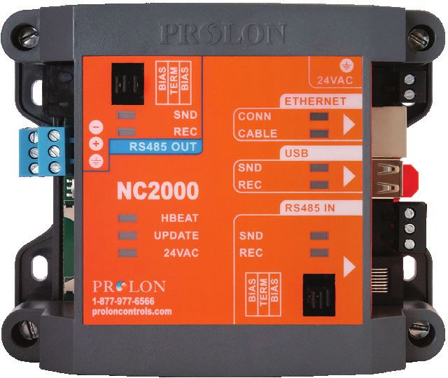
REV. 7.3.0 / PL-HRDW-NC2000-C/F-EN 4LEDs
The NC2000 has a variety of LEDs visible on the front cover that are linked to different functions of the controller. Each
LED is individually identified to help the user make a quick visual diagnostic of the controller’s activity and status.
Figure 2 - LEDs Identification
LED Descriptions
• 24 VAC: The NC2000 is receiving 24 VAC from the power • USB - SND: Indicates the transmission of data back
source onto the USB serial port.
• UPDATE: The NC2000 is waiting to receive a program- • ETHERNET - CABLE: The NC2000 is detecting electri-
ming update. This LED will light up for five seconds cally that another Ethernet device is connected to it
after start up to indicate a brief window during which through a CAT5 cable on its Ethernet jack.
the controller can be updated.
• ETHERNET - CONN: Indicates that a TCP/IP connection
• HBEAT: When this LED is blinking, the NC2000 is run- has been opened on the NC2000 through port 502.
ning in normal operation. Does not reflect the status of Cloud communication.
• RS485 IN - REC: Indicates reception of data from the • RS485 OUT - REC: Indicates reception of data from the
‘RS485 IN’ network bus. ‘RS485 OUT’ network bus.
• RS485 IN - SND: Indicates the transmission of data • RS485 OUT - SND: Indicates the transmission of data
back onto the ‘RS485 IN’ network bus. back onto the ‘RS485 OUT’ network bus.
• USB - REC: Indicates the reception of data from the
USB serial port.
REV. 7.3.0 / PL-HRDW-NC2000-C/F-EN 5Jumpers
The NC2000 has jumpers that are externally accessible that allow for configuration of the bias and terminating resistors
used on both RS485 communication ports.
RS485
OUT USB
RS485 IN
RS485
IN
Figure 3 - Location of the EXTERNAL jumpers
Activating a jumper enables the associated resistor on the respective communication port. To disable a resistor, remove
the jumper (setting the jumper on only a single pin is the same as removing it).
Bias Resistors: On a given RS485 bus, a single device must have the BOTH bias resistors enabled. The location of this
device is not important, as long as there is only one that has these resistors enabled. The bias resistors should be disabled
on the remaining devices.
Terminating Resistors: On a given RS485 bus, the devices at both extremities of the bus should have their terminating
resistors enabled. The terminating resistor should be disabled on all devices in between the extremities.
See the Prolon Network Guide or the RS485 protocol for more information about bias and terminating resistors.
Figure 4 - Jumpers
REV. 7.3.0 / PL-HRDW-NC2000-C/F-EN 6Communication Settings Reset Button
The NC2000 has a button located on the left side of the controller that can be used to reset the IP address, as well as other
important settings related to communication, in case they are forgotten or lost. After following the procedure described
below, the following settings will be in effect:
IP Address 192.168.1.99
Subnet Mask 255.255.255.0
Default Gateway 192.168.1.1
IP Mode Static
Modbus Address 99
Baud Rate 57600
To reset the communication settings of the NC2000, follow these steps:
1. Power up the NC2000 and wait for the blue heartbeat LED (HBEAT) to start blinking.
2. Hold down the Communications Reset Button for approximately 8 seconds, at which point the heartbeat LED will
stop blinking and the NC2000 will self-reset. Release the button.
3. After approximately 5 seconds, the NC2000 will resume normal operation, but will have the new communication
settings as described above.
Communication
Reset Button
HBEAT
Figure 5 - Communication Reset Button
In the case where only the IP settings have been forgotten, an alternative to using the communications reset button is
to communicate to the NC2000 using one of the other two inbound communication ports that are available: the USB
port or the RS485 IN port. The Prolon Focus software allows you visualize and edit the IP settings of the NC2000 in its
communications configuration page.
REV. 7.3.0 / PL-HRDW-NC2000-C/F-EN 7Communication Ports
Inbound Communication
The NC2000 has several inbound communication ports. These ports are intended to communicate with various user
interfaces such as PCs, laptops, tablets or smartphones equipped with Prolon Focus or Prolon Focus App software, either
locally or remotely through the internet. The messages received at the inbound ports are interpreted by the NC2000 and
then forwarded outwards to the Prolon RS485 network as required. The default Modbus address of the NC2000 itself,
regardless of the port being used, is 99.
Ethernet
USB
RS485 IN
Figure 6 - Inbound Communication
Ethernet Port - Cloud Communication
The Ethernet Port on the NC2000 allows for Prolon Cloud Communication. Cloud Communication works by posting
messages onto the Prolon Cloud server that the Network Controller detects and responds to. Cloud Communication is
encrypted and does not require any inbound port opened in the router so the network security is much greater.
Also, since the Network Controller is DHCP by default, Cloud Communication should be plug-and-play for most installa-
tions.
For higher security setups, the following outbound ports may need to be authorized in the router:
• 8080 to proxy.prolon.net for Cloud Communication
• 4225 for the Network Controller email alert service
Ethernet Port - TCP/IP
The Ethernet Port on the NC2000 is specifically designed to respond to incoming Modbus TCP/IP connections on TCP
port 502, such as those generated by Prolon Focus software.
Because the NC2000 is in DHCP mode by default, its local IP address may vary. Refer to your router for more information.
Alternatively, the NC2000 can be configured with a static IP address. This can be done by using the Communication
Settings Reset button (see p.7) to allow initial access, or by using one of the other connection ports (USB or RS485) to
perform the setup.
REV. 7.3.0 / PL-HRDW-NC2000-C/F-EN 8To be able to connect to the NC2000 from outside the local area connection, the building’s router must be set up for port
forwarding on TCP port 502. A static IP address or a dynamic DNS service may also be required to ensure connection
availability from the outside. Only one TCP/IP connection can be made at a time to the NC2000.
If configured to send out alert emails, the NC2000 will open a connection to port 4225 on Prolon’s external SMTP server
using encrypted authentication whenever an email needs to be sent.
USB Port
The USB port on the NC2000 acts as a communication port, allowing a user to connect and visualize the Prolon network
using a computer, tablet or smartphone. The USB port is not intended to be used to connect USB flash drives or other
peripherals.
The USB plug on the NC2000 is a female USB type ‘A’ connector. Therefore, a typical connection between a computer and
the NC2000 would require a male-to-male USB type ‘A’ cable.
Upon connecting your interface of choice to the NC2000 USB port, you may be prompted to provide the location of the
driver that should be used. These driver files can be found in the Prolon Focus folder, under “Drivers”. Once driver setup
is complete, the USB port will appear in the Focus software as an option in the Serial Port selection drop down list.
WARNING: USB wires connect the electrical commons of the two devices at both extremities. Please ensure that your
chosen interface (PC, laptop, etc…) shares the same common as the NC2000, or that one end is electrically floating (lap-
top running on batteries only, NC2000 using floating transformer, etc…). Prolon is not responsible for any damages to
your interface that may occur when connecting through USB.
RS485 IN Port
The NC2000 also comes equipped with an RS485 IN port that is only used for communication that is directed to the
NC2000 from a computer or other interface. The NC2000 acts as a Modbus RTU slave on this port and will not initiate
communication on its own. This is not the appropriate port to connect the rest of the Prolon controllers (rooftop con-
trollers, zone controllers, thermostats, etc…). Typical use of this port requires a USB to RS485 converter between your
computer and the NC2000.
The RS485 IN port is actually a group of two different connectors, both wired in parallel. Either connector in the group
can be used for inbound communication. The purpose of having these two connectors in parallel is simply to offer both
Modbus RTU physical connection types (two-wire bus or RJ45 jack). The RJ45 jack is internally wired to correspond to
the Modbus RTU specifications.
The remaining connector is a simple screw-type terminal block with three terminals for the A (+), B (-) and GND.
Figure 7 - RJ45 Pinout
REV. 7.3.0 / PL-HRDW-NC2000-C/F-EN 9Outboud Communication
The NC2000 only has a single outbound communication port, the RS485 OUT port. This port is intended to be wired to
the actual network of Prolon controllers communicating in Modbus RTU over RS485 (rooftop controllers, zone control-
lers, thermostats, etc…). On this port, the NC2000 acts as a network Master, initiating communication to the controllers,
polling them and distributing information.
This port will NOT respond to incoming messages from the Prolon Focus software or other devices, therefore any at-
tempt to connect to this port with your computer or RS485 converter is futile. Instead, use the RS485 IN port (on page 11)
for communication with a PC or other network master device.
The RS485 OUT port is actually a group of four different connectors, all wired in parallel. Any connector in the group
can be used for outbound communication. The purpose of having these four connectors in parallel is just to simplify
daisy-chaining.
Two of the connectors in the group are RJ45 jacks that are internally wired to correspond to the Modbus RTU specifica-
tions.
The remaining two connectors are simple screw-type terminal blocks with three terminals each for the A (+), B (-) and
GND. (See Figure 7)
Typical wiring setup is to daisy-chain this NC2000 outbound port to Prolon master controllers (rooftop controller, heat-
pump controller, etc…) on their respective inbound ports (INT ports). Bias and terminating resistors should be enabled as
required. The master controllers are then wired from their respective outbound port (NET port) to their respective slave
controllers (Zone controllers, thermostats, etc…).
See the Prolon Network Guide for more information on network topology and wiring.
RS485 OUT Port
Figure 8 - Outbound Communication
REV. 7.3.0 / PL-HRDW-NC2000-C/F-EN 10Technical Specifications Supply: 24 VAC ±10%, 50/60 Hz, Class 2 Consumption: 5 VA max Indication lights (LED): State of the communication ports / Power supply / Microprocessor state Microprocessor: ASIX AX11015, 8 bits, 25 MHz, 512 KB FLASH memory Battery: Super-capacitor 0.5F, keeps precise time for 10 days. This battery is only used to keep accurate time during power outages. Does not allow the NC2000 to keep transmitting data, send alarms or perform data logging. Communication: • Modbus TCP/IP (Static IP address or DHCP) • Modbus RTU (RS485), 1 Input port and 1 Output port, up to 127 nodes • USB Baud rates: 9600, 19200, 38400, 57600, 115200 SD Card: Standard size only, SDSC or SDHC, FAT16 or FAT32 Connections: Removable screw-type terminal blocks (16 AWG max) for power and RS485, modular RJ45 jacks for Ether- net / RS485, USB female type A for local PC connection and DIN Rail connector or 4 screws for panel mount. Dimensions: 5.39" x 4.41" x 2.25" (137 mm x 112 mm x 57 mm) Non-Condensing Weight: 0.9 lbs (0.41 kg) Environment: -4 to 122 ºF (-20 to 50 ºC) Non-Condensing Certification: UL916 Energy Management Equipment, CAN/CSA-C22.2, RoHS, FCC part 15: 2012 class B The performance specifications are nominal and conform to acceptable industry standards. Prolon Inc. will not be liable for damages resulting from misapplication or misuse of its products. REV. 7.3.0 / PL-HRDW-NC2000-C/F-EN 11
Compliance

   • cULus Listed; UL 916 Energy Management Equipment, File E364757, Vol.1

   • CAN/CSA-C22.2 No. 2015-12, Signal Equipment

   • FCC Compliant to CFR47, Part 15, Subpart B, Class B

   • Industry Canada (IC) Compliant to ICES-003, Issue 5: CAN ICES-3 (B)/NMB-3(B)

   • RoHS Directive (2002/95/EC)

FCC User Information
This device complies with Part 15 of the FCC Rules. Operation is subject to the following two conditions: (1) this device
may not cause harmful interference, and (2) this device must accept any interference received, including interference
that may cause undesired operation.

Caution: Any changes or modifications not approved by Prolon can void the user’s authority to operate the equipment.

Note: This equipment has been tested and found to comply with the limits for a Class B digital device, pursuant to part
15 of the FCC Rules. These limits are designed to provide reasonable protection against harmful interference in a resi-
dential installation. This equipment generates, uses and can radiate radio frequency energy and, if not installed and
used in accordance with the instructions, may cause harmful interference to radio communications. However, there is no
guarantee that interference will not occur in a particular installation. If this equipment does cause harmful interference
to radio or television reception, which can be determined by turning the equipment off and on, the user is encouraged
to try to correct the interference by one or more of the following measures:

   • Reorient or relocate the receiving antenna.

   • Increase the separation between the equipment and receiver.

   • Connect the equipment into an outlet on a circuit different from that to which the receiver is connected.

   • Consult the dealer or an experienced radio/TV technician for help.

Industry Canada
This Class (B) digital apparatus meets all the requirements of the Canadian Interference-Causing Equipment regulations.

Cet appareil numérique de la Classe (B) respecte toutes les exigences du Réglement sur le matériel brouilleur du Canada.

REV. 7.3.0 / PL-HRDW-NC2000-C/F-EN                                                                                     12
Overall Dimensions

                                                                                                                     4.41"
                                                                                                                  (112 mm)

                                                             5.39"
                                                           (137 mm)

                                                                                                                     2.29"
                                                                                                                   (58 mm)

                                              Figure 9 - NC2000 Size Diagram

REV. 7.3.0
PL-HRDW-NC2000-C/F-EN
© Copyright 2021 Prolon. All rights reserved.
No part of this document may be photocopied or reproduced by any means, or translated to another language without prior written
consent of Prolon. All specifications are nominal and may change as design improvements are introduced. Prolon shall not be liable for
damages resulting from misapplication or misuse of its products. All trademarks are the property of their respective owners.
REV. 7.3.0 / PL-HRDW-NC2000-C/F-EN                                                                                                13
You can also read