An overview of LTe PosiTioning - February 2012
←
→
Page content transcription
If your browser does not render page correctly, please read the page content below
An overview of LTE Positioning
February 2012

Rev. A 02/12
SPIRENT
1325 Borregas Avenue
Sunnyvale, CA 94089 USA

Email:   sales@spirent.com
Web:     http://www.spirent.com

Americas 1-800-SPIRENT • +1-818-676-2683 • sales@spirent.com

Europe and the Middle East +44 (0) 1293 767979 • emeainfo@spirent.com

Asia and the Pacific +86-10-8518-2539 • salesasia@spirent.com

© 2012 Spirent. All Rights Reserved.

Spirent Communications, a leader in networks, services and devices testing, offers Spirent
TestCenter™ Virtual, the industry’s first solution specifically designed to holistically validate
the performance of all elements of the data center and cloud computing environments
including virtual machines, servers and storage devices.

All of the company names and/or brand names and/or product names referred to in this
document, in particular, the name “Spirent” and its logo device, are either registered
trademarks or trademarks of Spirent plc and its subsidiaries, pending registration in
accordance with relevant national laws. All other registered trademarks or trademarks are the
property of their respective owners.

The information contained in this document is subject to change without notice and does not
represent a commitment on the part of Spirent. The information in this document is believed
to be accurate and reliable; however, Spirent assumes no responsibility or liability for any
errors or inaccuracies that may appear in the document.
An Overview of LTE Positioning

Contents
Introduction . . . . . . . . . . . . . . . . . . . . . . . . . . . . . . . . . . . . . . . . . . . . . . . . . . . . 1

LTE Positioning Technologies . . . . . . . . . . . . . . . . . . . . . . . . . . . . . . . . . . . . . . . 2

     Cell ID and Enhanced Cell ID . . . . . . . . . . . . . . . . . . . . . . . . . . . . . . . . . . . . 2

     Assisted Global Navigation Satellite Systems . . . . . . . . . . . . . . . . . . . . . . 4

     Observed Time Difference of Arrival . . . . . . . . . . . . . . . . . . . . . . . . . . . . . . 5

Positioning Architecture in LTE Networks . . . . . . . . . . . . . . . . . . . . . . . . . . . . . 7

LTE Positioning Protocol . . . . . . . . . . . . . . . . . . . . . . . . . . . . . . . . . . . . . . . . . . . 8

Control Plane Positioning . . . . . . . . . . . . . . . . . . . . . . . . . . . . . . . . . . . . . . . . . .9

User Plane Positioning . . . . . . . . . . . . . . . . . . . . . . . . . . . . . . . . . . . . . . . . . . . 10

Area Event Triggering . . . . . . . . . . . . . . . . . . . . . . . . . . . . . . . . . . . . . . . . . . . . 11

Emergency Positioning . . . . . . . . . . . . . . . . . . . . . . . . . . . . . . . . . . . . . . . . . . . 11

Support for Multi-Location Technologies . . . . . . . . . . . . . . . . . . . . . . . . . . . . 12

Summary . . . . . . . . . . . . . . . . . . . . . . . . . . . . . . . . . . . . . . . . . . . . . . . . . . . . . . 12

                                                                                                  Spirent white paper • i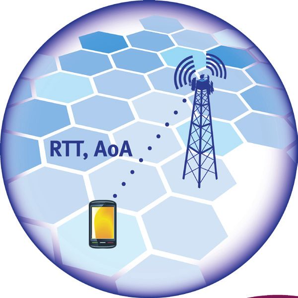
An Overview of LTE Positioning

introduction
                       Demand for mobile services is exploding and one of the
                                                                                              FCC E911
                       fastest growing segments is Location Based Services (LBS),
                                                                                             Requirement
                       primarily driven by two major requirements: emergency
                       services and commercial applications. For emergency                    2D error for a
                       services, the most significant driver is the FCC’s E911 mandate         given set of
                       in the US, which requires location (with certain accuracy             measurements:
                       limits) of emergency callers to be provided. A wide variety            67% < 50m
                       of commercial applications, such as maps and location-                 95%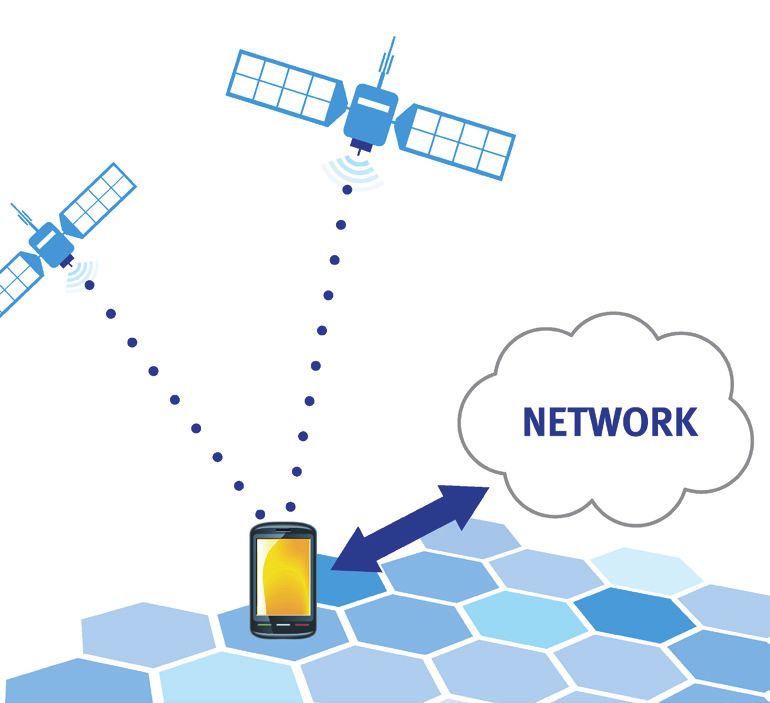
An Overview of LTE Positioning

LTE Positioning Technologies
                      3GPP Release 9 for LTE defines support for three handset based positioning
                      technologies: ECID, A-GNSS, OTDOA and LPP, a new positioning protocol. The following
                      sections describe each of these technologies in detail.

                      Cell ID and Enhanced Cell ID
                      Cell ID (CID) positioning is a network based technique that can be used to estimate
                      the position of the UE quickly, but with very low accuracy. In the simplest case, the
                      position of the UE is estimated to be the position of the base station it is camped on.
                             Cell ID positioning performance can be improved by measuring certain network
                                   attributes, a technique called Enhanced Cell ID (ECID). In ECID, the
                                      Round Trip Time (RTT) between the base station and the UE is used to
                                         estimate the distance to the UE. In addition, the network can use the
                                          Angle of Arrival (AoA) of signals from the UE to provide directional
                                          information. See Figure 1.

                                          The RTT is determined by analyzing Timing Advance (TA)
                                          measurements, either from the eNodeB or by directly querying the
                                          UE. The eNodeB tracks two types of TA measurements – Type 1
                                         and Type 2. Type 1 is measured by summing the eNodeB and the UE
                                       receive-transmit time differences. Type 2 is measured by the eNodeB
Figure 1: ECID positioning          during a UE Random Access procedure.

                      AoA is measured based on uplink transmissions from the UE and the known
                      configuration of the eNodeB antenna array. The received UE signal between successive
                      antenna elements is typically phase-shifted by a measurable value. The degree of
                      this phase shift depends on the AoA, the antenna element spacing, and the carrier
                      frequency. By measuring the phase shift and using known eNodeB characteristics, the
                      AoA can be determined. Typical uplink signals used in this measurement are Sounding
                      Reference Signals (SRS) or Demodulation Reference Signals (DM-RS).

                                                                                        Spirent white paper   • 2
An Overview of LTE Positioning

                       As stated earlier, CID positioning has very low accuracy, typically equating to the size
                       of the cell the UE is camped on (which may be in the order of kilometres). ECID is able
                       to provide better accuracy in comparison to CID; the main sources of error in ECID are
                       receive timing uncertainty (which affects the RTT calculation) and multipath reflections.

                         Summary of CID/ECID positioning

                            Principle
                            Use knowledge of the serving cell, Round Trip Time and Angle of Arrival of the
                            uplink signal to position the UE

                            Key Use Cases
                            Quick, coarse fix as an input to other, more accurate positioning technologies
                            Fall back methods in case A-GNSS/OTDOA are unavailable

                            Accuracy
                            Typically 150m or coarser

     ECID is able to provide better accuracy in comparison to CID;
     the main sources of error in ECID are receive timing uncertainty
     (which affects the RTT calculation) and multipath reflections.

3   • Spirent white paper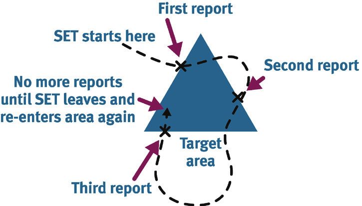
An Overview of LTE Positioning

                               Assisted Global Navigation Satellite Systems (A-GNSS)
                               GNSS refers collectively to multiple satellite systems, such as GPS and GLONASS.
                               With conventional standalone GNSS, the GNSS receiver in the mobile device is solely
                               responsible for receiving satellite signals and computing its location. The receiver needs
                               to acquire satellite signals through a search process; it must lock onto at least four
                               satellites in order to compute a 3-D position. The acquisition process can be demanding
                               in terms of battery and processing power, and TTFF can be long.

                                              The performance of standalone GNSS can be significantly improved by
                                              a technique called Assisted GNSS. See Figure 2. In a typical A-GNSS
                                              implementation, the standalone GNSS facilities of the phone are augmented
                                              by data provided by the network, termed “Assistance Data”, which includes
                                              information the mobile GNSS receiver can use to accelerate the process of
                                              satellite signal acquisition. The final position can be calculated by either the
                                              UE or the network and shared with third parties (such as emergency PSAPs1).
                                              A-GNSS speeds up positioning performance, improves receiver sensitivity
                                              and helps to conserve battery power. A-GNSS works well outdoors and in
                                              scenarios where a reasonably good view of the sky is available. Performance
                                              is generally poor in environments with high obscuration and multipath, such
                                              as indoors and in dense urban settings.
Figure 2: A-GNSS positioning
                               Currently, two global systems are fully operational – GPS and GLONASS. Although
                               mobile receivers have traditionally supported positioning using A-GPS alone, it
                               is possible to use both satellite systems simultaneously to acquire a position.
                               The advantage of this technique is to effectively increase the number of satellites
                               available for signal acquisition, and it can improve performance in high-obscuration
                               environments like cities. Assistance data can be provided by the LTE network for both
                               GPS and GLONASS satellites (as well as Galileo and QZSS when these systems are fully
                               operational).

                                    Summary of A-GNSS positioning

                                      Principle
                                      Use standalone GNSS with help from the LTE network to speed up the position
                                      calculation process

                                      Key Use Cases
                                      Highly accurate, technology of choice for positioning

                                      Accuracy
                                      Typically 10 – 50m

                               1
                                   PSAP - Public Safety Answering Point.

                                                                                                      Spirent white paper   • 4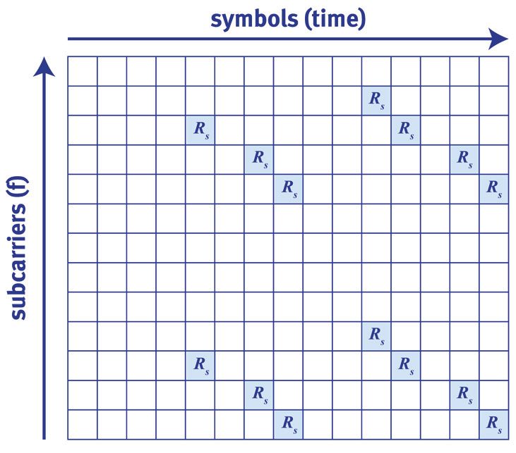
An Overview of LTE Positioning
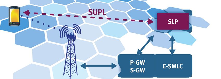
Observed Time Difference of Arrival (OTDOA)
OTDOA techniques are similar in principle to the GNSS position calculation
methodology. The UE measures time differences in downlink signals from two or
more base stations. Using the known position of the base stations and these time
differences, it is then possible to calculate the position of the UE. Generally, the signals
used for OTDOA are cell Reference Signals (RS). See Figure 3.
Figure 3: OTDOA positioning
In LTE, the measured time difference between the RS from the serving cell and one or
more neighboring cells is known as Reference Signal Time Difference (RSTD). In order
to calculate the position of the UE, the network needs the positions of the eNodeB
transmit antennas and the transmission timing of each cell (which can be challenging if
the eNodeBs are asynchronous).
One of the biggest challenges faced by LTE OTDOA is the requirement to measure
neighboring cell RS accurately enough for positioning. To overcome this problem,
special positioning sub frames have been defined in Release 9 called Positioning
Reference Signals (PRS). See Figure 4. These special reference signals can assist in the
measurement of neighboring cell signals by increasing RS energy.
One of the biggest challenges faced by LTE OTDOA is the
requirement to measure neighboring cell RS accurately enough
for positioning. To overcome this problem, special positioning
sub frames have been defined in Release 9 called Positioning
Reference Signals.
5 • Spirent white paper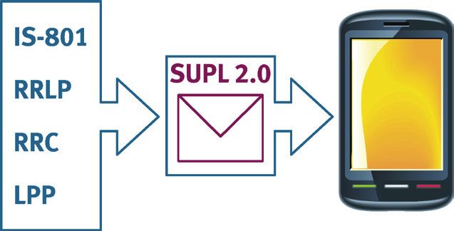
An Overview of LTE Positioning

Figure 4: Structure of the PRS

The PRS is periodically transmitted along with the cell specific RS in groups of
consecutive downlink sub frames. In a fully synchronized network, these positioning
sub frames overlap, allowing for reduced inter-cell interference. In the case that the PRS
patterns in two neighboring cells overlap, the network may mute the transmissions to
improve signal acquisition. The network can also provide Assistance Data to the UE to
aid its acquisition of the PRS. This data usually consists of relative eNodeB transmit
timing differences (in the case of a synchronous networks), search window length, and
expected PRS patterns of surrounding cells.

In LTE, OTDOA and A-GNSS may be used together in a “hybrid” mode. Since the
fundamental positioning calculation approach is the same, a combination of satellites
and base station locations can be used in the position calculation function. In this
technique, the UE measures the RSTD for at least one pair of cells and satellite signals,
and returns the measurements to the network, which is responsible for analyzing the
measurements and calculating a position. This hybrid mode can be expected to provide
better accuracy than OTDOA positioning alone, and is a key enabler for improving
positioning accuracy in challenging environments.

  Summary of OTDOA positioning

     Principle
     Use time difference of arrival of special Positioning Reference Signals (PRS) from
     2 or more LTE base stations

     Key Use Cases
     Fallback technology when GNSS is not available
     Positioning indoors and environments without clear sky visibility

     Accuracy
     50-200m (based on simulation)

                                                                  Spirent white paper     • 6
An Overview of LTE Positioning
Time Difference of Arrival technologies in 2G/3G services – an overview
CDMA AFLT GSM E-OTD WCDMA OTDOA-IPDL
In AFLT, CDMA pilot signals are In E-OTD, the UE measures OTDOA in WCDMA is
used for measuring the time the time difference of arrival characterized by Idle Periods
difference of arrival. CDMA base at its receiver of burst signals in Down Link (IPDL) to
stations are synchronized with from different BTS’s. A allow the UE to listen to
GPS time, which eliminates Location Measurement Unit neighboring cell signals
timing offsets between base (LMU) is used to synchronize which otherwise are subject
stations and optimizes hybrid BTS timing. to interference from the
AFLT + A-GNSS positioning. stronger serving cell signal.
Disadvantages of OTDOA in GSM/WCDMA
Clock errors, lack of Base Station synchronization, cost of deploying LMUs and heavy signaling
overhead discouraged use of these technologies for commercial purposes.
Positioning architecture in LTE networks
Positioning information exchange between the UE and the LTE network is enabled by
the LTE positioning protocol. LPP is similar to protocols such as RRC, RRLP, and IS-801
already deployed in 2G and 3G networks2. LPP is used both in Control Plane and User
Plane (enabled by SUPL 2.0). The key entity in the core network that handles positioning
is the Evolved Serving Mobile Location Center (E-SMLC). The E-SMLC is responsible for
provision of accurate assistance data and calculation of position.
SUPL 2.0 can be deployed across 2G, 3G and 4G networks to provide one common user
plane protocol. In initial LTE deployments, it is possible to use SUPL 2.0 with RRLP over
LTE, which helps in enabling user plane positioning before implementing LPP. So in
summary, positioning in LTE networks can be accomplished in one of three ways.
LTE positioning methods
CONTROL PLANE with LPP
SUPL 2.0 with RRLP
SUPL 2.0 with LPP
2
Note that RRLP only supports A-GNSS; delivery of LTE ECID and OTDOA information is not supported.
However, SUPL 2.0 has native support for sending information about the serving LTE and neighboring cells.
7 • Spirent white paperAn Overview of LTE Positioning
LTE Positioning Protocol
Positioning over LTE is enabled by LPP, which is designed to support the positioning
methods covered previously. LPP call flows are procedure based, where each procedure
has a single objective (for example, delivery of Assistance Data).
The main functions of LPP are
• to provision the E-SMLC with the positioning capabilities of the UE
• to transport Assistance Data from the E-SMLC to the UE
• to provide the E-SMLC with co-ordinate position information or UE measured
signals
• to report errors during the positioning session.
LPP can also be used to support “hybrid” positioning such as OTDOA + A-GNSS.
In the case of network based positioning techniques, the E-SMLC may require
information from the eNodeB (such as receive-transmit time difference measurements
for supporting ECID). A protocol called the LPP-Annex (LPPa) is used to transport this
information.
LPP
OTDOA
ECID
A-GNSS
EXTENSIONS TO LPP (LPPe)
LPP was designed to enable the key positioning methods (with enhancements)
available on 2G and 3G networks, and provide the minimum set of data
necessary for positioning. The OMA has proposed extensions to LPP (LPPe)
which can be used to carry more data to improve existing positioning
techniques as well enable new methods (such as WLAN positioning). LPPe is
primarily considered a User Plane positioning enabler.
Spirent white paper • 8An Overview of LTE Positioning
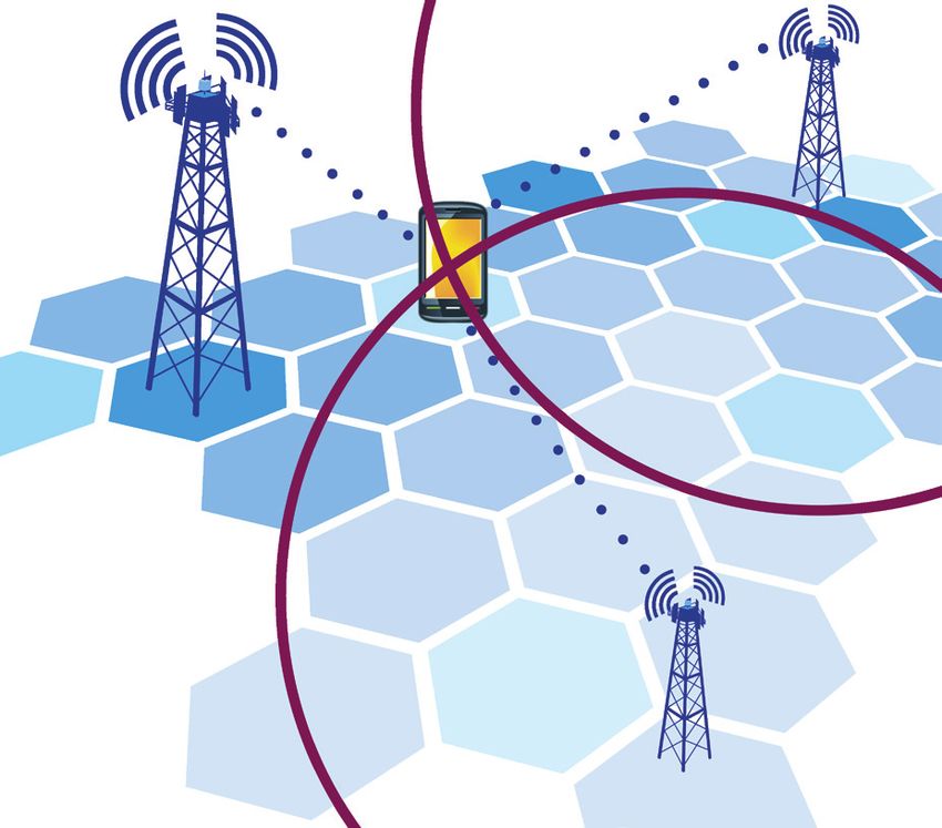
Control Plane Positioning
With Control Plane implementations, most commonly used in emergency services,
positioning messages are exchanged between the network and the UE over the
signaling connection. In LTE, control plane positioning is enabled by the Mobility
Management Entity (MME), which routes LPP messages from the E-SMLC to the UE using
NAS Downlink Transfer Messages. See Figure 5. Control Plane positioning is quick,
reliable and secure.
Figure 5: Control Plane Positioning
Control Plane Call Flows
Network Initiated Location Request (NILR) – Primarily used for emergency
positioning. The network instructs the UE to provide a position, and may send
unsolicited Assistance Data
Mobile Terminated Location Request (MTLR) – Initiated by the network, this
differs from NILR with the addition of privacy features – the user can reject the
location request.
Mobile Originated Location Request (MOLR) – The positioning session is
initiated by the UE, which contacts the MME with the request. The remainder of
the call flow is similar to NILR.
9 • Spirent white paperAn Overview of LTE Positioning
User Plane Positioning
User Plane Positioning over LTE uses the data link to transmit positioning information,
and is enabled by the SUPL protocol. SUPL 2.0 supports positioning over LTE as well as
2G and 3G networks, and provides a common user plane platform for all air interfaces3.
SUPL does not introduce a new method to package and transport Assistance Data,
instead it uses existing control plane protocols (such as RRLP, IS-801 and LPP). See
Figure 6. SUPL uses the data link to transmit positioning information, and is enabled by
an entity called the SUPL Location Platform (SLP). The SLP handles SUPL messaging,
and is typically able to interface with the E-SMLC for obtaining Assistance Data. SUPL
messages are routed over the data link via the LTE P-GW and the S-GW entities. See
Figure 7.
SUPL 2.0 enables a complex feature set that is pertinent to mobile applications,
including area based triggering, periodic reporting and batch reporting. SUPL 2.0
also features support for emergency positioning over the data link, and support for
major positioning technologies (including multi-location technologies such as WiFi
positioning).
The primary positioning enabler in SUPL 2.0
is an underlying control plane protocol (such
as RRLP or LPP). This implies that SUPL 2.0
can be used over any network, as long as
the SLP and SMLC are able to interface and
agree upon a common positioning protocol.
IP data This flexibility is very useful in initial LTE roll
connection outs, as it allows operators to enable SUPL
over any air 2.0 positioning over an existing control
interface plane protocol such as RRLP.
Figure 6: SUPL 2.0 supports multiple control plane protocols
Figure 7: SUPL 2.0 network architecture
3
For more information, please see the following reference guide “Secure User Plane Location 2.0 Reference
Guide” and the two webinars “Unleash the Business Potential of LBS Over LTE Using SUPL 2.0” and
“SUPL 2.0 Conformance Requirements for LTE” on www.spirent.com.
Spirent white paper • 10An Overview of LTE Positioning
Area Event Triggering
SUPL 2.0 features the use of geographical ‘triggers’, which enable the UE to report its
position if it enters, leaves, or is within a particular area. Triggering may be enabled
either by the network or by the SET, with the two entities agreeing on trigger criteria.
Area Event triggers enable key mobile applications such as Check-in services, shopping
deals and offers, location based advertising, and child location. The key factor
determining the effectiveness of triggers is how accurate the obtained position is.
Key Trigger Criteria
Type of trigger
List of target areas
Start and stop time
Measurement reporting criteria
Number of times to re-use the trigger
Emergency Positioning
Emergency Positioning in 2G and 3G networks has been processed over control plane,
as user plane protocols did not have the necessary network elements to support such a
requirement. SUPL 2.0 introduces an entity known as the Emergency SLP (E-SLP) which
can co-ordinate with the IP Multimedia Subsystem (IMS) in LTE networks to enable
positioning over an emergency call. The E-SLP functionality can be added to an existing
SLP used by the network. When an emergency call is in process, the IMS coordinates
the call with a Network Initiated Location Request from the E-SLP. Emergency
positioning may override user notification and privacy settings, and receive priority
over all non-emergency SUPL sessions. Emergency sessions are typically initiated by a
Session Initiation Protocol (SIP) Push.
11 • Spirent white paperAn Overview of LTE Positioning
Support for Multi-location technologies
One of the goals of SUPL 2.0 is to serve as a single, unifying user plane protocol
independent of air interface. SUPL 2.0 can be used over 2G, 3G and LTE, with full
support for the key positioning techniques and positioning protocols used in these
networks. A key feature of SUPL 2.0 is flexibility in protocol use – for example, RRLP can
be used to transfer assistance data over an LTE air interface.
SUPL 2.0 supports reporting of cell information for all major cellular wireless
technologies as well as wireless LAN access point info. This feature, termed multi
location ID, allows a location server to process many different types of measurements
in order to calculate a more accurate position.
In future, SUPL 3.0 will support extensions to the LPP protocol (LPPe). These extensions
serve to include additional information to enhance existing positioning techniques as
well as to provide a bearer for new positioning methods (such as sensor positioning and
Short Range Node positioning).
Summary
Since the LBS market is growing rapidly in size and scope, enabling high accuracy
positioning both indoors and outdoors, is essential to validate the commercial promise
of the enabling technology, as well as to meet the FCC’s emergency mandate in the US.
2G and 3G networks have used a variety of positioning techniques, such as A-GNSS,
Cell ID and AFLT to satisfy positioning requirements. LTE introduces pivotal technologies
that are not only able to provide adequate positioning performance for emergency and
commercial purposes, but also to seamlessly transition from existing technologies. The
deployment of LPP and SUPL 2.0 enables a diverse set of features, such as geofencing,
emergency positioning over user plane, and multi-location technologies such WiFi
Positioning. However, this advanced feature set comes at the cost of increased
complexity, requiring comprehensive conformance and performance testing to fully
validate the technologies.
LTE introduces new positioning technologies that are complex
and will require extensive verification to provide adequate
positioning performance for emergency and commercial
purposes.
Spirent white paper • 12You can also read