HR 1600 COUGAR HORIZONTAL WINDLASS
←
→
Page content transcription
If your browser does not render page correctly, please read the page content below

T H E      W O R L D   P O W E R   I N   A N C H O R I N G   S Y S T E M S

                                               HR 1600 COUGAR
                                          HORIZONTAL WINDLASS

HR1200 COUGAR                           www.muir.com.au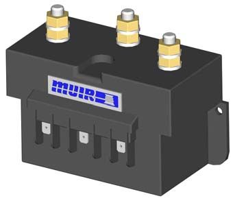
T H E      W O R L D   P O W E R   I N   A N C H O R I N G   S Y S T E M S

                            IMPORTANT:
             MANUAL OVERIDE PAWL
     The pawl and bolt assembly herewith is to be fitted to forward side
     of Horizontal Windlass Housing, in the event of Manual Override
     being used to manually retrieve chain.

     The pawl is NOT designed to be laid on at anchor, use a chain
     stopper, devil claw or snubbed line.

     Do not reverse the winch with the pawl engaged as damage will
     result to the pawl and housing.

     Therefore remove the pawl from the winch and store in a safe
     place after using the manual override.

HR1200 COUGAR                           www.muir.com.au
T H E W O R L D P O W E R I N A N C H O R I N G S Y S T E M S
Contents
Introduction page 1
Important Information
Safety
Installation page 2
Chain pipe Fitting page 3
Manual Override System (MORS)
Rope Chain Management System adjustment
Depth of chain locker page 4
Handy hints page 5
Manual Operation
Anchoring
Retrieving chain
Rope Hauling on Capstan
Electrical information page 5
Circuit breaker
Deck switch
Isolating switch
Batteries
Rotation
Wiring layout page 6
Operating Instructions page 7
Servicing
Maintenance Instructions page 8
Rope/Chain splice page 9
Line care
Trouble Shooting
Warranty and Warranty Registration Card page 10
Deck Template
Deck Template to suit all models
Wiring Diagram
All HR1200 Cougar Models - 12/24V DC Two Wire 1000W motor
Exploded View Drawings
HR 1200/1600 Single Gypsy / Capstan
HR 1200/1600 Single Gypsy Only
HR 1200/1600 Twin Capstans
HR 1200/1600 Single Gypsy / Capstan (left hand)
HR1200 COUGAR www.muir.com.auT H E W O R L D P O W E R I N A N C H O R I N G S Y S T E M S INTRODUCTION Thank you for purchasing a Muir Windlass. Muir go to great lengths to develop anchoring systems that not only meet all your performance and safety requirements, but at the same time are designed with a style and finish that enhances the aesthetics of your vessel. With Muir’s commitment to quality and the use of superior materials and processes we know you will be pleased with your investment, and rest assured that through the correct installation, operation and maintenance your new Muir Windlass will give you years of reliable performance. IMPORTANT INFORMATION To avoid damage to the gear drive, windlass or vessel when bringing the anchor up hard, it is a preferred practice to mark the chain at approximately 5-meter intervals from the anchor, to alert the operator to the anchor position. Alternatively an Auto Anchor can be used. Under no circumstances should the windlass be operated if it is stalled or overloaded. If anchor retrieval is impaired by high wind, heavy seas or the anchor is snagged, ease the load by either motoring or sailing slowly forward into the wind with a chain stopping device in place. The rope or chain should be cleared off and the anchor driven out by the engine, otherwise the gearbox or shaft can be damaged. SAFE OPERATION • Ensure that hands, feet, hair and clothing are kept clear of the windlass and other loose gear when in operation. • Ensure no one is swimming nearby when the anchor is being lowered or retrieved. • Keep hands well clear of capstan, gypsy, chain and rope. • The windlass should never be used for lifting people aloft. • Do not use a windlass as a bollard for mooring, towing or being towed. • When the windlass is at lay or the anchor stowed, always ensure the clutch is tightened with the clutch handle, and a Chain lock, Devils claw or Snubber Line is fitted to retain the anchor. The use of these accessories will prevent excessive loads on the geardrive and accidental release of the anchor. HR1200 COUGAR www.muir.com.au 1
T H E   W O R L D        P O W E R           I N   A N C H O R I N G              S Y S T E M S

 INSTALLATION

                                      Figure(1)
                                      Locate the windlass centrally fore and aft. Check that the chain
                                      leads unhindered to the anchor roller. The chain leads onto the top
                                      side of the starboard gypsy, wraps around 100° and falls below
                                      deck through the chain pipe (hawser). Ensure there is sufficient
                                      room around the windlass to allow full rotation of the windlass
                                      manual/clutch handle (if supplied).

   1                                  Figure (2)
                                      The centre line of the gypsy must be in the same plane as the
                                      chain lead from the bow roller. If the deck is angled (fore & aft) or
                                      curved (port to starboard) a suitably shaped mounting block will
                                      be required to spread the load evenly over the deck surface and
                                      mount the windlass base on a level and even footing.
                                      Figure (3)
  2
                                      Place the shaped mounting block (if required) onto the deck.
                                      Using the layout template supplied, mark the mounting centres
                                      and drill the holes 11mm (7/16”) for the deck bolts of 10mm (3/8”).
                                      Mark the chain pipe centres at this time. (Refer template).
                                      Figure (4)
                                      Apply an appropriate sealant to the base plate and mounting
                                      block (if required) and carefully tighten the nuts & washers onto
  3                4                  the deck bolts under the deck. Remove excess sealer.
                                      For Aluminium or Steel hull vessels, it is important to insulate the
                                      windlass with a non-conductive gasket to avoid corrosion. This also
                                      applies below deck with the mounting bolts, nuts and washers.
                                      Where the deck construction is light or of foam sandwich
                                      construction, a plywood stiffener of at least 16mm (5/8") should be
                                      fitted to the underside of the deck to spread the load and to
                                      prevent the bolts from pulling through the deck. Large diameter
                                      washers on the underside of the stiffener assists to spread the load.

  5                                   Figure (5)
                                      1. Mount the windlass from above as shown.
                                      Figure (6)
                                      2. From below, place washers and nut on each stud and tighten.

                                      For fitting of the chain pipe or RCMS see next page
  6

 NOTE: On assembly, grease all moving parts with a Lithium/teflon based grease.

HR1200 COUGAR                                      www.muir.com.au                                      2
T H E W O R L D P O W E R I N A N C H O R I N G S Y S T E M S
Horizontal Winch Chain pipe Fitting
1. To position the chain pipe (A), first align the stripper (B) with the
centre of the gypsy.
2. Wrap the chain (D) around the gypsy (C) and through the chain
pipe to position the chain pipe correctly.
3. Align the stripper to the inside of the chain as it falls vertically into
the chain locker.
4. Mark the chain pipe position and drill the bolt holes, finally cut out
the section for the chain to pass through the deck and then bolt
the chain pipe into place.
Horizontal Winch Chain pipe with Rope/Chain Management System Fitting
1. Position the chain pipe (A) so that the peeler (B) is directly under
the centre of the gypsy (C), and the finger sits on top (D).
2. Slide the S/S stripper (E), over the middle of the gypsy lining it up
with the hole in the peeler for the screw (F).
3. Fit the stripper with the screw making sure the countersunk head
is inside the chain pipe. Tighten with washer and nylock nut
4. Check the position of the chain pipe and make sure the stripper
does not hit the gypsy when it is rotating. Spot the holes for the
chain pipe on the deck with the chain pipe in position. Remove
the chain pipe and drill the mounting holes. Refit the chain pipe,
checking its position again, and fasten it to the deck.
5. To tension the rope finger, loosen the grub screw (G), behind the
finger in the chain pipe, and turn the pin (H), towards the gypsy
with a large screwdriver.
Manual Override System (MORS)
This allows the operator to manually recover the anchor and anchor rode without the use of the electrics. For
manual operation the locking pawl should be first engaged into the gypsy, this stops the gypsy from running
back wards, the clutch should be released marginally by turning in an anti-clockwise direction. Now the gypsy is
free to turn and the manual override handle can be moved in a clockwise direction to engage the gypsy, when
pulling in an anti-clockwise direction the MOR pawl will engage and drive the gypsy retrieving the chain, as the
handle is moved clockwise the weight will be taken by the locking pawl.
Rope/Chain Management System (RCMS)
Optional chain pipe kits (with pipe, special 180 degree stripper and spring loaded finger are available. The rope
finger pawl guides the rope and chain around the gypsy and through this special chain pipe.
The standard chain pipe with its integral stripper is normally supplied when otherwise specified or ordered by the
customer.
Adjustment: Firm tension of the finger is required to reduce rope (nylon Line) slipping through the gypsy. Check
the spring tension (at least) annually and re-tension the spring when needed. To adjust this tension (if your line is
slipping) refer to the procedure below.
Procedure:
1. Loosen the grub screw on the chain pipe with an Allen key for finger adjustment.
2. Turn the screwdriver clockwise to tension the spring, while holding the tension re-tighten the grub screw
HR1200 COUGAR www.muir.com.au 3T H E W O R L D P O W E R I N A N C H O R I N G S Y S T E M S
DEPTH OF THE CHAIN LOCKER
Measuring the vertical distance (minimum fall) underside of the deck and the top of the completely stored and
heaped anchor rode in the locker will assist in determining the installation to suit your vessel. Refer to the fall depth
diagrams to the left, and the options detailed below. It is also recommended that the chain be directed to the
center of the chain locker.
Vertical Windlass:
The running gear, gypsy and capstan are positioned above the
deck with the motor and gear drive below. Vertical windlasses
operate at best with greater anchor rode fall than the horizontal
MINIMUM FALL windlass and a minimum fall of 300mm from top of stacked
anchor rode is recommended. This is particularly important if
using nylon line, which does not fold and stack as well as chain.
Vertical windlasses minimise deck intrusion and the modern
curved lines of the Muir windlass enhance the look of any vessel.
A vertical windlass provides the advantages of a I 80-degree
wrap of the anchor rode around the gypsy.
Horizontal Windlass:
Fully enclosed, above deck, this style is usually preferred where
locker space is limited or additional fall is required. The motor and
gear drive is fully enclosed in the housing with nothing protruding
MINIMUM FALL below deck. The horizontal windlass operates with optimum
anchor rode fall of at least 300mm from the top of the stacked
anchor rode, and due to the horizontal orientation of the gypsy
higher above the deck there is additional fall provided. These
units are ideally suited for vessels with less locker space.
Minimum Fall
Vertical Windlass Model Horizontal Windlass Model (Dist. Top of Pile)
VR/C 600 HR 600 / 700 / 806 / 808 300 mm
VR/C 850 / 1250 / 2200 HR 1200/1600 450 mm
VR/C 2500 / 3500 HR 2500 / 3500 650 mm
VR/C 4000 HR 4000/- 4200 800 mm
HR1200 COUGAR www.muir.com.au 4T H E W O R L D P O W E R I N A N C H O R I N G S Y S T E M S
HANDY HINTS
It is a common mistake to locate the windlass too far forward, or too close to the bulk head, where there is
insufficient room for chain and anchor stowing. The chain fail position should be in the centre of the chain locker.
If the chain falls alongside a bulkhead or onto the stem it will pyramid and jam.
If the chain falls into an undesirable position, a metal tube can be fitted under the hawser to redirect the chain
to a preferred position. This pipe should be at least 1 ½ times the width of the chain. It should also have as much
vertical angle as possible. Position the windlass in the best location with the chain hawser facing forward. Ensure
sufficient room to run electric cables to the windlass. Follow the instructions on page 4 including underdeck
stiffening, deck camber, alignment, mounting blocks and sealing procedures.
ELECTRICAL
See Wiring Diagrams for wiring instructions.
Circuit breaker (must be fitted to ensure warranty)
If the windlass is overloaded or stalled the circuit breaker automatically cuts off power to the windlass and
protects the wiring and motor. The circuit breaker should not be used as an isolating switch, purely for safety
reasons.
Deck Switches are best located out to either port or starboard or directly behind the windlass in a position
where it can be easily reached with your foot or knee, preferably where you can view the anchor and chain
coming aboard.
Isolating Switch should be fitted in an accessible position for safety, ideally close to the battery or switches. The
isolating switch is not a circuit breaker.
Batteries are best located as close to the windlass as possible. Larger cables will reduce the voltage drop
to the motor and the heat generated when running the windlass. Small diameter cables drop voltage
considerably. Use the following table as a guide to your required wire size:
Cable Size
Distance from battery to motor (m) Cable Diameter (mm)
(mm2) AWG
7 (23’) 25 3 8 (5/16”)
9 – 17 (30’ – 55’) 50 1 10 (3/8”)
Rotation: Windlasses may be wired for single or dual direction, using single or dual deck switches for raising or
lowering. Alternatively a remote control solenoid packages with Toggle Switch, Hand Pendant or Auto Anchors
are available.
3 POLE
SOLENOID Solenoid Installation
We recommend that the solenoid is installed in an
upright position, where it has no exposure to sea
water but is in close proximity to the electric motor of
the windlass.
For wiring information, please refer to the
appropriate wiring diagram.
WINCH MODEL MOTOR SIZE MOTOR TYPE
HR 1200 1000 W 3 POLE
This way up
HR1200 COUGAR www.muir.com.au 5T H E W O R L D P O W E R I N A N C H O R I N G S Y S T E M S
TOGGLE SWITCH LAYOUT
3
1. BATTERY 4
2. CIRCUIT BREAKER
3. SOLENOID/CONTROL BOX 2
4. TOGGEL SWITCH
1
4
3 5
1. BATTERY 2
2. CIRCUIT BREAKER
3. SOLENOID/CONTROL BOX
1
4. DECK SWITCHES
5. TOGGLE SWITCH
6
4
5
3
AUTO ANCHOR LAYOUT
2
1. BATTERY
2. CIRCUIT BREAKER
3. SOLENOID/CONTROL BOX 1
4. DECK SWITCHES
5. AUTO ANCHOR
6. AUTO ANCHOR SENSOR
For wiring information, please refer to the appropriate wiring diagram.
OGG NOT BE USED AS WIRING DIAGRAMS
HR1200 COUGAR www.muir.com.au 6T H E W O R L D P O W E R I N A N C H O R I N G S Y S T E M S
OPERATING INSTRUCTIONS
Manually Releasing chain: To release the anchor rode, place the handle onto the clutch nut as shown in the
diagram at the bottom of the page and turn anti-clockwise to release the clutch brake. Let the anchor fall
and control the run of the chain by tightening handle clockwise using the clutch mechanism as a brake.
Anchoring: When laying at anchor use a chain stopper, nylon/chain bridle or snubber line to prevent
snatching and direct load on the windlass main shaft. Never use the windlass as a mooring bollard!!
Retrieving Chain: Before operating the windlass tighten the clutch with the handle in a clockwise direction,
then remove the handle. If the anchor is buried hard, motor forward to pull it free after hardening up on the
windlass, to ease the load on the windlass.
Rope Hauling on the Capstan: The capstan can be operated independantly of the gypsy. Secure the anchor
rode (via Chainlock, Gypsy lock or Snubber) then release the clutch. The windlass capstan can now be
operated separately.
Electric operation: To release the anchor down reverse the motor by pushing remote switch to “down” which
drops the chain and the anchor immediately. When the anchor is at the desired depth, the windlass can be
stopped by letting go of the switch, the chain and rope can then be lowered further by releasing the manual
clutch. Always keep well clear of the windlass when releasing or retrieving the chain and anchor. Keep fingers,
hair and clothing well clear when the windlass is in operation.
Auto Anchor Launching: Two direction windlasses are now standard. If the anchor and anchor roller can be
positioned so that it falls as soon as the windlass is reversed, the whole operation can then be carried out
remotely from aft or fly bridge. Remote switch controls are self-centering and stop the windlass when the
switch is released. Mark the anchor end of the chain at 2 and 5 metre (6.5’ & 16.5’) intervals which will enable
the operator to judge when the anchor is almost up. Go gently with the last two metres of retrieving the
anchor by letting go of the switch, rather than waiting for the anchor to fly up over the roller and bang tight,
putting excessive load onto the bow roller, windlass and fore deck.
SERVICING
The geardrive is filled and sealed at factory with long life synthetic oil and does not require replacement.
A rinse of fresh water on all your deck gear after every excursion ensures all salt deposits and corrosion are
kept to a minimum.
Regularly clean the clutch cones and re-apply a thin film of water proof grease to the cone surfaces. This
ensures smooth running of the gypsy and chain when the manual freefall is operated.
We recommend the windlasses of Pleasure Vessels are stripped yearly and all moving parts cleaned and
greased with a Marine Grease, Teflon or Lithium based grease (e.g. Duckhams'Keenol'; 'Castrol LMX'.). In the
case of Work and Charter Vesels we suggest it is carried out more frequently. Do not use soap based grease.
Manually Releasing chain
Tighten to brake the outgoing line
Fully tighten to retrieve the anchor under power
Gradually loosen to release
the line manually
HR1200 COUGAR www.muir.com.au 7T H E W O R L D P O W E R I N A N C H O R I N G S Y S T E M S
MAINTENANCE INSTRUCTIONS
You will require the following tools to complete this procedure:
(i) Clutch/Manual recovery handle
(ii) 14mm(9/16”) Socket & 3” extension bar with rachet.
(iii) A Lithium/Teflon based marine grease.
(iv) HR1200 Exploded view drawing: K08-COMHR1200
1 1. Removing Clutch Nut
& Hex head Screw. Place 14mm (9/16”) Socket onto
(A) Screw and turn anti-clockwise to remove. Now
the Clutch nut (B) can be removed by turning it anti-
clockwise (this may require the initial use of the
Clutch/Manual recovery handle).
A B
2 2. Removing Gypsy
& D-cone The D-cone & Gypsy (C) is now free to
remove from the Main Shaft (D).
D
3. Greasing (if no further maintenance is required)
After removing the gypsy & D-cone it is now possible
C to grease the exposed Main shaft & cone (E). Then
3 reverse the above steps to re assemble. (Also see
Note on bottom of page)
4. Removing Capstan.
Place 14mm(9/16”) Socket onto (F) Screw and turn
anti-clockwise to remove. Now the Capstan can be
E
removed. Taking Care. Not to lose the capstan drive
4 key.
F
5. Greasing
Slide Shaft out partly as shown, then generously
grease (G) the surface/bore of bush and exposed
Main Shaft
5 G
6. Re-assembly
Before re-assembly, grease the exposed Main
Shaft/cone (H) & Gypsy bore (I). To complete the
service or replacement of parts reverse the above
steps.
Note:
6 • We recommend the use of Lithium/Teflon
based grease.
• We also recommend that the windlass be
serviced at least yearly.
H In the case of Work/Charter Vessels the windlass may
I require a more regular servicing
HR1200 COUGAR www.muir.com.au 8T H E W O R L D P O W E R I N A N C H O R I N G S Y S T E M S
Rope/Chain Splice.
1. To stop rope unravelling, seize rope 400mm(16") from end with
whipping twine. Unlay strands.
2. After placing 20mm (3/4") of heat shrink sleeve tubing through the
last link of chain, pass one strand of rope through sleeve and chain
from one side and the other two strands of rope from the opposite side.
(See illustration).
3. While pulling all three strands tight, shrink the sleeve tightly onto the
rope using a hairdryer / fan heater or by immersing in boiling water.
4. Remove seizing and complete back splice in normal manner for two
full tucks. With a hot knife pare down the three strands by 113 and
insert two further tucks. Pare down by another1/3 and finish with two
tucks. Cut any remaining tails.
Line Care
Using the wrong type of line may cause the line to jam causing excessive line wear. Muir Windlasses are
designed to run on 3-strand nylon line (supplied by Muir) which has been specially treated with fabric
softener to prevent it from hardening. It is recommended to soak your rope in fresh water containing fabric
softener every 3 months.
In case of a rope jam, slacken off the windlass clutch to free the jammed line. When retrieving the anchor
rode do not continue to run the windlass if the anchor or chain is jammed, as line slippage in the gypsy will
cause damage to the line.
Trouble Shooting
ELECTRICAL
1. Check the battery circuit breaker and ensure the isolating switch is on.
2. Check battery is charged up to 12 or 24 volts.
3. Check that the foot switch plunger is contacting
4. Check remote control solenoid is contacting, if this is clicking the problem may be low voltage, a
faulty solenoid or a wire not properly connected.
5. Check wiring between controls, solenoid and motor are in-tact.
6. If the motor will not turn after checking the above points, check that the motor bushes are not worn or
sticking.
MECHANICAL
If the windlass running gear will not turn or operate check the following
1. Check that the clutch beside the chain gypsy is tightened to the chain gypsy drive using the manual
handle supplied (see operating instructions).
2. If the line slips check the tension on the finger and increase spring tension (see RCMS adjustment on
this page).
HR1200 COUGAR www.muir.com.au 9T H E W O R L D P O W E R I N A N C H O R I N G S Y S T E M S
WARRANTY
Limited for period of One year (First Owner)
We warrant each new product manufactured by us to be free from defects in material and workmanship for a period
of 1 year (first Owner).
This warranty shall become effective only upon receipt of a completed warranty registration, which shall identify the
product so registered by serial number. This warranty shall remain in effect for a period of one (1) year from the date
of purchase. Where fitted to Charter/Hire/Commercial boats the warranty is limited to 6 months, if prior approval of
type selection has not been approved by Muir.
Conditions
While this warranty applies to defects in material and workmanship, it does not apply to:
• Normal worn parts or to damage caused by neglect, lack of maintenance, accident or improper
service/installation or service by persons other than an authorised Muir representative.
• Muir shall not be responsible for failures due to products being used in applications that they are not intended for,
or exceed the products performance specifications.
• For warranty claim, defective product must be returned to Muir for inspection.
• Muir will not be responsible for freight charges, removal or installation labour on warranty claims.
• Damage due to unsatisfactory storage or use of equipment prior to installation in the approved/intended manner.
Exclusions
All incidental and/or consequential damages are excluded from this warranty. Warranties of merchantability and
fitness are excluded from this warranty. Implied warranties are limited to the life of this warranty. Some countries do
not allow limitations on how long an implied warranty lasts or the exclusion or limitation of incidental or consequential
damages, so the above may not apply to you.
We reserve the right to improve the design or materials used on any product without assuming any obligation to
modify any product previously manufactured or used.
Liability
Muir Engineering liability under this warranty shall be to the exclusion of all other warranties or liabilities (to the extent
permitted bylaw). In particular (but without limitation) Muir Engineering shall not be liable for any:
• indirect or consequential loss including (without limitation),
• loss of anticipated profits, damage to reputation or goodwill, loss of expected future business, damages, costs or
expenses payable to any third party or any other indirect losses,
• damage to yachts or equipment.
• death or personal Injury (unless caused by Muir Engineering negligence).
----------------------------------------------------------------------------
-
WARRANTY REGISTRATION CARD
Return To
MUIR ENGINEERING PTY. LTD.
100 Browns Rd, Kingston
Tasmania, Australia, 7050
Customer / Company Name: Winch Model:
Contact (if Company): Serial Number:
Address: Purchase Date:
dd / mm / yyyy
Purchased From:
Phone / Email: Invoice Number / Receipt Number / Proof of Purchase:
HR1200 COUGAR www.muir.com.au 10ITEM PART NUMBER DESCRIPTION QTY 1 P22-HSGHR1200B HOUSING ALLOY HR1200 COUGAR TW IN GYP 1 2 K06-SFTHR1200G SHAFT ASSEMBLY HR1200 COUGAR TC 1 3 P22-BPLALLHR01200 BASE PLATE ALLOY HR1200 COUGAR 1 4 P02-NOVHR01200CLHL BEARING LEVER HANDLE NOV HR1200C L/HAND 2 5 P02-GSH035.0025.052 SPACER GUARDSHAFT HR1200C CAPSTAN 2 6 P04-CAPBRZ01200C CAPSTAN BRONZE HR1200C COUGAR 2 7 P21-BRS031.8009.503 W ASHER BRASS 1-1/4" X 3/8" X 3MM 2 8 S13-30409.52025 BOLT HEX HD SS304 0-3/8 X 1 INCH 2 9 P02-NYL025.0010.517 BUSH NYLON HR1200C COUGAR FOOT 4 10 S33-30404.76013 SCREW CSK SL MT 304 0-3/16 X 0-1/2 INCH 4 11 R41-ORG04203503.5 'O' RING SEAL 42X35X3.5 (BS220) 2 12 S76-30409.52 W ASHER SPRING SS304 3/8 INCH 2 13 S75-30428.00050 W ASHER FLAT SS304 1" X 2" X 10G 2
ITEM   PART NUMBER           DESCRIPTION                              QTY
  1    P22-HSGHR1200B        HOUSING ALLOY HR1200 COUGAR TW IN GYP     1
  2    K06-SFTHR1200A        SHAFT ASSEMBLY HR1200 COUGAR SG/SC        1
  3    P07-CLNBRZHR01200C    CLUTCH NUT BRONZE HR1200 COUGAR 3 PRONG   1
  4    P08-CNEBRZHR01200CD   'D' CONE BRONZE HR1200C COUGAR            1
  5    P11-HANAB2LEV01200C   HANDLE LEVER AB2 HR1200C COUGAR           1
  6    P02-NOVHR01200CLHL    BEARING LEVER HANDLE NOV HR1200C L/HAND   1
  7    P22-BPLALLHR01200     BASE PLATE ALLOY HR1200 COUGAR            1
  8    P02-NOVHR01200CLH     BEARING LEVER HANDLE NOV HR1200C COUGAR 1
  9    P02-GSH035.0025.052   SPACER GUARDSHAFT HR1200C CAPSTAN         1
  10   P04-CAPBRZ01200C      CAPSTAN BRONZE HR1200C COUGAR             1
  11   P21-BRS031.8009.503   W ASHER BRASS 1-1/4" X 3/8" X 3MM         1
  12   S13-30409.52025       BOLT HEX HD SS304 0-3/8 X 1 INCH          1
  13   S45-30407.94013       SCREW SHCS SS304 5/16 X 0-1/2 INCH        1
  14   P13-BRZLEVHR1200CL    PAW L LEVER HANDLE HR1200C COUGAR LH      1
  15   S13-30409.52038       BOLT HEX HD SS304 0-3/8 X 1-1/2 INCH      1
  16   P02-303013.5009.314   BUSH SS303 HR1200C COUNTERW EIGHT PAW L   1
  17   P13-BRZCW GHR1200C    PAW L COUNTERW EIGHT HR1200C COUGAR       1
  18   S36-30409.52013       SCREW HEX HD SS304 3/8 X 0-1/2 INCH       1
  19   S75-30409.52019       W ASHER FLAT SS304 3/8 INCH X 0-3/4 INCH  2
  20   P02-NYL025.0010.517   BUSH NYLON HR1200C COUGAR FOOT            4
  21   P11-HAN304EXHR1200C   HANDLE EXTENSION 304 HR1200C COUGAR       1
  22   S33-30404.76013       SCREW CSK SL MT 304 0-3/16 X 0-1/2 INCH   4
  23   R41-ORG04203503.5     'O' RING SEAL 42X35X3.5 (BS220)           2
  24   S33-30406.35025       SCREW CSK SL MT 304 0-1/4 X 1 INCH        2
  25   S76-30409.52          W ASHER SPRING SS304 3/8 INCH             1
  26   S75-30428.00050       W ASHER FLAT SS304 1" X 2" X 10G          1
  27   S75-30409.52025       W ASHER FLAT SS304 3/8 INCH 1 LGE/OD      1
ITEM   PART NUMBER           DESCRIPTION                              QTY
  1    P22-HSGHR1200A        HOUSING ALLOY HR1200 COUGAR SG/SC         1
  2    K06-SFTHR1200A        SHAFT ASSEMBLY HR1200 COUGAR SG/SC        1
  3    P07-CLNBRZHR01200C    CLUTCH NUT BRONZE HR1200 COUGAR 3 PRONG   1
  4    P08-CNEBRZHR01200CD   'D' CONE BRONZE HR1200C COUGAR            1
  5    P11-HANAB2LEV01200C   HANDLE LEVER AB2 HR1200C COUGAR           1
  6    P02-NOVHR01200CLH     BEARING LEVER HANDLE NOV HR1200C COUGAR 1
  7    P22-BPLALLHR01200     BASE PLATE ALLOY HR1200 COUGAR            1
  8    P02-NOVHR01200CCS     BEARING CAPSTAN SIDE NOV HR1200C COUGAR   1
  9    P02-GSH035.0025.052   SPACER GUARDSHAFT HR1200C CAPSTAN         1
  10   P04-CAPBRZ01200C      CAPSTAN BRONZE HR1200C COUGAR             1
  11   P21-BRS031.8009.503   W ASHER BRASS 1-1/4" X 3/8" X 3MM         1
  12   S13-30409.52025       BOLT HEX HD SS304 0-3/8 X 1 INCH          1
  13   S45-30407.94013       SCREW SHCS SS304 5/16 X 0-1/2 INCH        1
  14   P13-BRZLEVHR1200C     PAW L LEVER HANDLE HR1200C COUGAR         1
  15   S13-30409.52038       BOLT HEX HD SS304 0-3/8 X 1-1/2 INCH      1
  16   P02-303013.5009.314   BUSH SS303 HR1200C COUNTERW EIGHT PAW L   1
  17   P13-BRZCW GHR1200C    PAW L COUNTERW EIGHT HR1200C COUGAR       1
  18   S36-30409.52013       SCREW HEX HD SS304 3/8 X 0-1/2 INCH       1
  19   S75-30409.52019       W ASHER FLAT SS304 3/8 INCH X 0-3/4 INCH  2
  20   P02-NYL025.0010.517   BUSH NYLON HR1200C COUGAR FOOT            4
  21   P11-HAN304EXHR1200C   HANDLE EXTENSION 304 HR1200C COUGAR       1
  22   S33-30404.76013       SCREW CSK SL MT 304 0-3/16 X 0-1/2 INCH   4
  23   R41-ORG04203503.5     'O' RING SEAL 42X35X3.5 (BS220)           2
  24   S33-30406.35025       SCREW CSK SL MT 304 0-1/4 X 1 INCH        2
  25   S76-30409.52          W ASHER SPRING SS304 3/8 INCH             1
  26   S75-30428.00050       W ASHER FLAT SS304 1" X 2" X 10G          1
  27   S75-30409.52025       W ASHER FLAT SS304 3/8 INCH 1 LGE/OD      1
QTY   PART NUMBER           DESCRIPTION                              QTY
 1    P22-HSGHR1200A        HOUSING ALLOY HR1200 COUGAR SG/SC         1
 2    K06-SFTHR1200H        SHAFT ASSEMBLY HR1200 COUG SINGLE GYP     1
 3    P07-CLNBRZHR01200C    CLUTCH NUT BRONZE HR1200 COUGAR 3 PRONG   1
 4    P08-CNEBRZHR01200CD   'D' CONE BRONZE HR1200C COUGAR            1
 5    P11-HANAB2LEV01200C   HANDLE LEVER AB2 HR1200C COUGAR           1
 6    P02-NOVHR01200CLH     BEARING LEVER HANDLE NOV HR1200C COUGAR 1
 7    P22-BPLALLHR01200     BASE PLATE ALLOY HR1200 COUGAR            1
 8    P02-NOVHR01200CCS     BEARING CAPSTAN SIDE NOV HR1200C COUGAR 1
 9    P02-GSH035.0025.052   SPACER GUARDSHAFT HR1200C CAPSTAN         1
 10   S13-30409.52025       BOLT HEX HD SS304 0-3/8 X 1 INCH          1
 11   P21-BRS050.8009.505   W ASHER BRASS 2" X 3/8" X 5 MM            1
 12   S45-30407.94013       SCREW SHCS SS304 5/16 X 0-1/2 INCH        1
 13   P13-BRZLEVHR1200C     PAW L LEVER HANDLE HR1200C COUGAR         1
 14   S13-30409.52038       BOLT HEX HD SS304 0-3/8 X 1-1/2 INCH      1
 15   P02-303013.5009.314   BUSH SS303 HR1200C COUNTERW EIGHT PAW L   1
 16   P13-BRZCW GHR1200C    PAW L COUNTERW EIGHT HR1200C COUGAR       1
 17   S36-30409.52013       SCREW HEX HD SS304 3/8 X 0-1/2 INCH       1
 18   S75-30409.52019       W ASHER FLAT SS304 3/8 INCH X 0-3/4 INCH  2
 19   P02-NYL025.0010.517   BUSH NYLON HR1200C COUGAR FOOT            4
 20   P11-HAN304EXHR1200C   HANDLE EXTENSION 304 HR1200C COUGAR       1
 21   S33-30404.76013       SCREW CSK SL MT 304 0-3/16 X 0-1/2 INCH   4
 22   R41-ORG04203503.5     'O' RING SEAL 42X35X3.5 (BS220)           2
 23   S33-30406.35025       SCREW CSK SL MT 304 0-1/4 X 1 INCH        2
 24   S76-30409.52          W ASHER SPRING SS304 3/8 INCH             1
 25   S75-30409.52025       W ASHER FLAT SS304 3/8 INCH 1 LGE/OD      1
Head Office:
100 Browns Road,
Kingston Tasmania,
Australia 7050
Tel Int: +61 (0) 3 6211 8811
Fax Int: +61 (0) 3 6229 7030
Email: info@muir.com.au
www.muir.com.au

   WINDLASS
   SERIAL NUMBER

© 2005 Muir Engineering Pty. Ltd. Muir reserves the right to alter specifications without
notice. All rights reserved.

While all due care and attention has been taken in the preparation of this manual no
responsibility shall be taken for errors or omissions.
You can also read