Hydraulic Boat Lift Owner's Manual Assembly and Trouble Shooting Guide - 1270 N. River Drive Mankato, Minnesota 56001 Phone (800) 658-7010 Fax ...
←
→
Page content transcription
If your browser does not render page correctly, please read the page content below
Hydraulic Boat Lift
                                           Owner’s Manual

                                          Assembly and
                                 Trouble Shooting Guide

        1270 N. River Drive ▪ Mankato, Minnesota 56001
Phone (800) 658-7010 ▪ Fax (507)388-6348 ▪ info@pierpleasure.com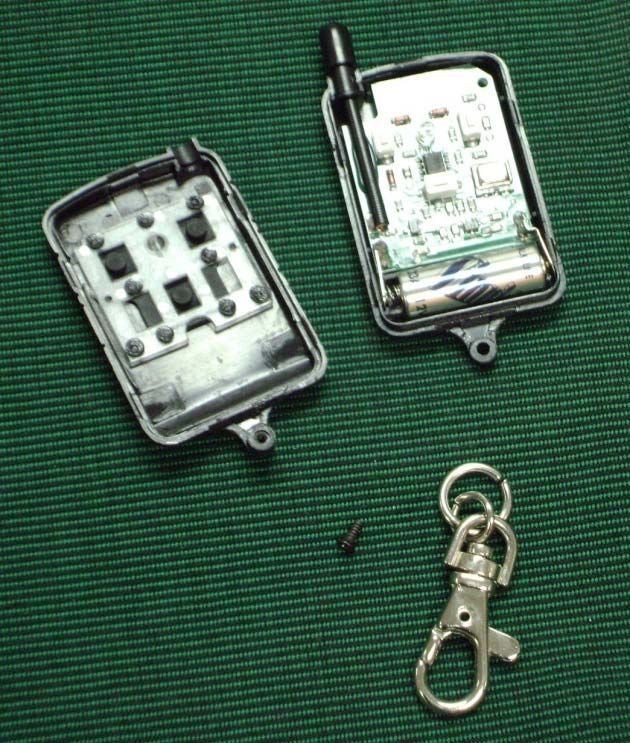
W A R N I N G
                              (READ THIS SECTION FIRST)
                         HYDRAULIC LIFT SAFETY INSTRUCTIONS
1.     Read all instructions and instruct all users about the proper operating procedures.
2.     Make sure all nuts and bolts are tightened properly before use.
3.     Grease pins that have zerks yearly for enhanced performance.
4.     Lift must be level with water line to operate properly.
5.     Do not allow anyone to swim or play near the lift. Keep everyone clear during operation of the lift.
6.     Hydraulic lifts raise and lower quickly. THINK before pushing the power switch and WATCH what you are doing!
7.     Stop lowering the bunk once the boat is floating.
8.     Weight of the boat must be positioned on the lift correctly or damage may occur to lift.
       See page 10 for proper positioning of boat.
9.     Do not exceed the maximum lift capacity. Exceeding lift capacity may lead to equipment failure
       and/or personal injury.
10.    If you do not have a canopy or boat cover, rain water in boat could cause the lift to become overloaded resulting in
       failure. Remove drain plug from boat when unattended.
11.    Inspect cables periodically for fraying. Replace cable if excessively frayed.
12.    Inspect pulleys to ensure that they turn freely. Replace excessively worn pulleys.
13.    Completely lower the boat lift when any maintenance is done to lift.
14.    Do not work in or on your boat when raised up in the lift.
15.    To prevent damage to lift canopy and/or boat while lifting, determine a maximum height stopping point and mark it.
       See page 9 on how to mark the stopping point.
16.    Always wear eye protection and gloves to protect yourself when connecting and disconnecting hoses to prevent
       high pressure fluid spray from penetrating your eyes and skin.
17.    Do not disconnect hoses from pump while the system is under load. The pressure in the hydraulic hoses will make
       it difficult to connect the hoses again.
18.    In the off-season, store hydraulic pump box in an environment where it will not freeze. This will prolong the life of
       the battery and hydraulic fluid. If the hydraulic fluid’s chemical properties change from freezing or it becomes
       contaminated, the fluid will need to be changed. See included instructions on changing hydraulic fluid.
19.    Never attempt to grab cable with your hand while operating lift. Personal injury may occur.
20.    Keep hose couplers free of dirt, dust and other debris to prevent contamination of the hydraulic pump.
21.    When lift is not used for an extended period of time, install the lock pin into the correct hole on the hydraulic beam
       assembly. Hydraulic fluid from the cylinder may flow slowly back into pump while you are gone. The lock pin will
       stop the lift from lowering. See page 9 for the installation and removal of this lock pin.
22.    Watches, jewelry and other metal objects that come in contact with electrical system will spark and
       cause significant injury. Always remove all jewelry and shut off the system switch before working inside
       the hydraulic box. (Turn the Green Knob)
23.    System shut-off switch should be turned off when lift is not in use. (Turn the Green Knob) This will disengage
       power to the pump and prevent accidental use of the remote by children or other users. See page 7 for the proper
       use of the system shut-off switch.
24.    Your Pier Pleasure limited warranty does not cover ice damage. Do not leave any Pier Pleasure product in
       the water during winter months. Leaving product in freezing water in all situations is not recommended. Any
       liability for damages caused by leaving product in freezing water will not be covered under warranty.
25.    Never operate the lift with the remotes unless the lift is in view. Unattended operation of the lift could cause
       damage to the lift and bodily harm to anyone around the boat lift.
26.    Do not let anyone swim or play under or around the boat lift or dock. Keep clear during operation of the lift.
       No jumping from, diving off or running on the dock or near the boat lift. Severe head, neck, back injury or
       death could result. Wear Personal Floatation Device (PDF) for added protection when on the dock.
                     Hydraulic lifts raise and lower quickly.
     THINK before pushing the power switch and WATCH what you are doing!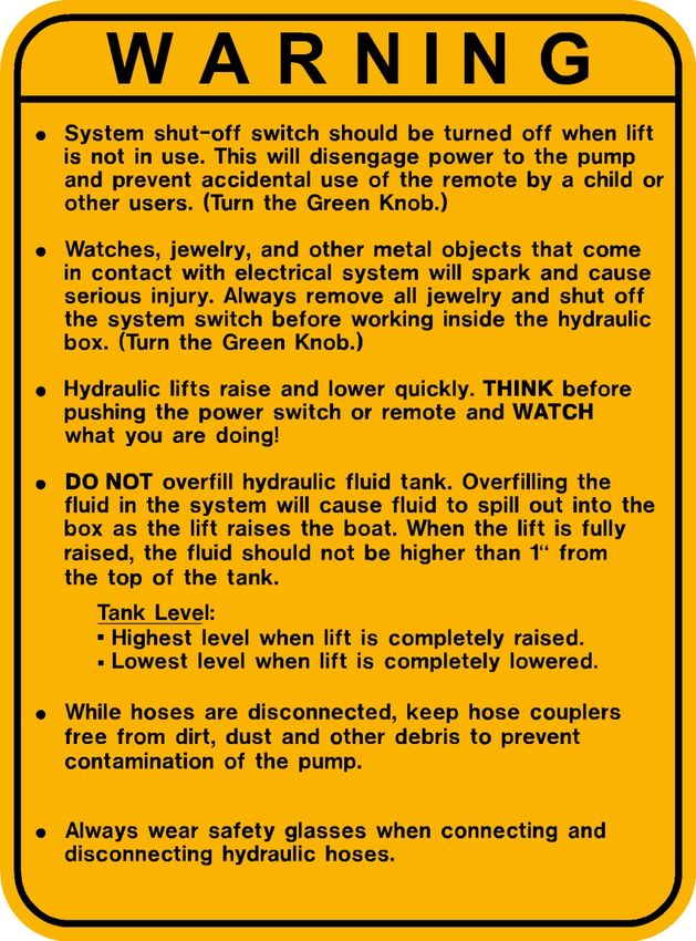
Thank you for your investment you have made in Pier Pleasure. Table of Contents
We appreciate the confidence you have put in our product and us.
Please read the instructions thoroughly. If you have any Safety Instructions
questions, please contact your dealer. May your Pier Pleasure Read Warnings First!
hydraulic boat lift bring you many years of enjoyment. This manual
is a supplement to the main Pier Pleasure Owner’s Manual that Installation of Hydraulic Unit
shows assembly and operation of the vertical lift. Please contact Beam Assembly Installation 4
your dealer if need additional manuals or assistance. Cable Installation 4
Coupling Hoses to Pump 6
Securing Hoses and Cords 6
Battery Hook-Up (12 Volt) 7
System Shut-Off Switch (12 Volt) 7
Powering System (110 Volt) 7
Hydraulic Lift Operation
Operating Lift with Remote 8
Operating Lift with Toggle Switch (12 Volt) 8
Operation Lift with Control Pad (110 Volt) 8
Marking a Stop Point 9
Use of Lock Pin When Not In Use 9
Access Hole 9
Proper Positioning of Boat 10
Programming Remote Fobs (12 Volt) 11
Operation of Control Pad (110 Volt) 12
Programming Remote Fobs (110 Volt) 12
Adding Hydraulic Fluid 13
Storage for Off-Season 13
Canopy Light 14
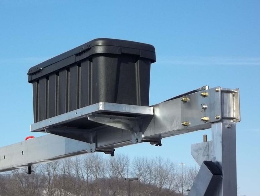
Hydraulic Accessories
Solar Panel and Solar Panel Rod 15
Hydraulic Box Rack 15
Trouble Shooting 16 – 22
Hydraulic Lift Warranties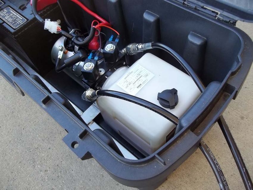
Hydraulic Beam Assembly Installation
  The hydraulic beam assembly is attached to
  the canopy arms of the lift with use of 3/8”
  bolts and brass nuts. If you do not have a
  canopy, short inner legs are available to
  attach the beam assembly. The hydraulic
  beam assembly is very heavy and will
  require additional help to lift into place.
  Place beam into position and install canopy
  arms or short inner legs. Tighten all bolts for
  canopy arms and hydraulic beam.

  See Additional photos on page 5.

 Cable Installation
 The cable from the hydraulic beam assembly is installed though the bunk beam. There are two
 sheaves located in the bunk beam that will have be removed and reinstalled into the beam. If you
 are adding this hydraulic system to an existing boat lift with a winch cable, that cable will also have
 to be removed. Slide the cable from the hydraulic beam through the beam re-install the sheaves.
 The threaded rod on the end of the cable is placed through the hole in the flat bar on the opposite
 side. Place two brass nuts on the threads to properly secure the cable.

                                                                                     Canopy Arm or
                                                                                     Short Inner Leg
   Cable installed through the bunk beam                                           Hoses to Pump
   and back up to the other side.

                                                              Load Beam with
                                                                Single Cable

   Cable installed through load beam and
   secured into flat on the upright opposite                          SIDE VIEW
   of the hydraulic beam. Use 2 brass nuts
   to secure the cable.

Page 4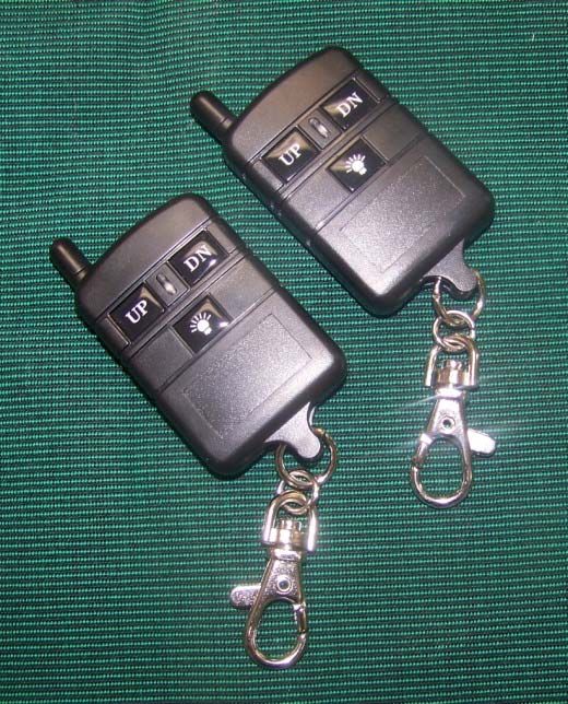
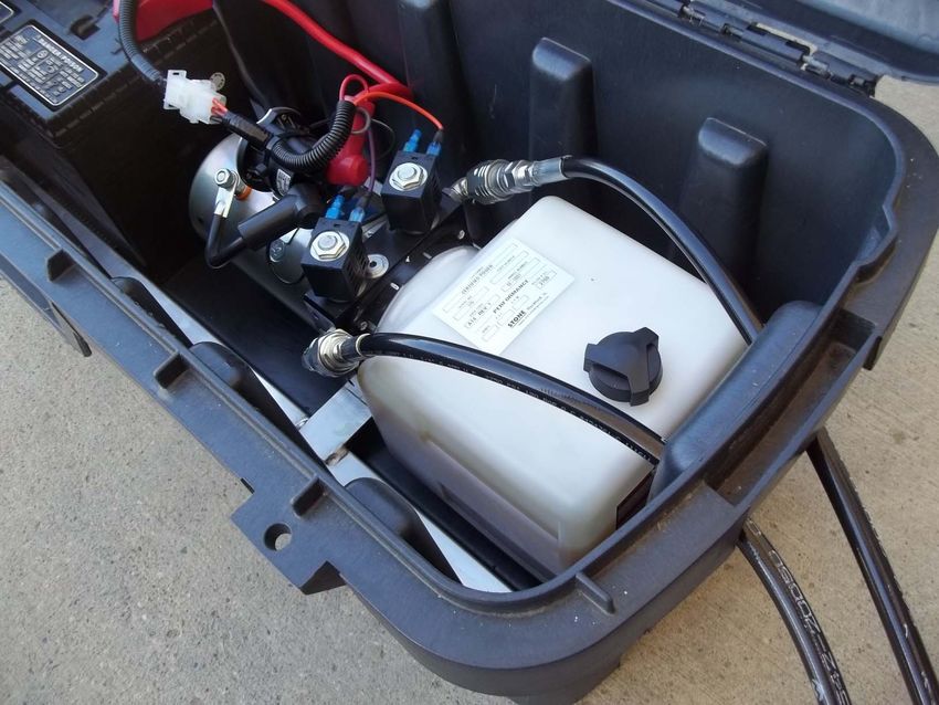
Coupling Hoses to Pump
The hoses from the hydraulic beam assembly
are connected to pump in the box. Slide hoses
through holes located on the side of the box.
Before connecting the hoses, clean dirt and
debris from connections. Debris in the pump
will cause the pump to fail. To attach the hoses,
align matching connections, turn and firmly
tighten with adjustable wrench. If the
connections are not tight, the pump will not
operate properly.

 Always wear eye protection and heavy
gloves when connecting and disconnecting
hydraulic hoses to prevent high pressure
fluid spray from penetrating the skin.

                                          Page 5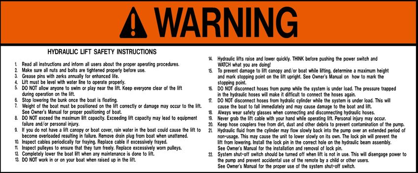
Battery Hook-Up – 12 Volt System (DC)
The battery is not supplied with the 12 volt
hydraulic system. A 12 volt deep-cycle marine
battery is recommended. The battery must have a
good charge for the hydraulic system to work
properly. Start with charging the battery
completely.

Place the battery in the open end of the black box
and attach the battery cables. Tighten battery
cable for a good connection.

RED IS POSITIVE ( + )    BLACK IS NEGATIVE ( - )

System Shut-Off Switch - 12 Volt System (DC)
The 12 volt hydraulic system is equipped with a
shut-off switch. The remote could operate your lift
from a great distance. To prevent accidental
usage by children who find the remote, use the
system shut-off switch to disable the system
when not in use. The switch has a green knob
and is connected to the battery. Tighten knob
down clockwise to operate the lift. Loosen knob
up counterclockwise to shut-off the system.
Watches, jewelry and other metal objects
that come in contact with electrical system
will spark and cause significant injury.
Always remove all jewelry and shut off the
system switch before working inside the
hydraulic box.

Page 6
Operating Lift with the Remote & Toggle Switch - 12 Volt System (DC)
The 12 volt hydraulic lift system is standard with three button remotes and a toggle switch. The
toggle switch is located inside the hydraulic box attached to the cover. Either the remote or the
toggle switch can be used to raise and lower the lift. Use caution when you activate the power.
If the remote is not responding properly, use the toggle switch to raise the lift. The remote will
not respond properly if the 12 volt battery is low, the signal between the remote and receiver is
weak or the remote fob battery is dead. Additional remotes are available through your dealer.
See page 11 for 12 volt system remote programming.
                                                                                     Toggle Switch

      Remote Key Fobs

                                                                                                Page 7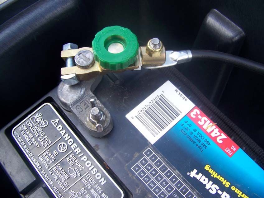
Marking Stop Point
The hydraulic lift rises very quickly. Damage to
your boat and lift canopy could occur. Raise the
lift in small increments the first time you raise the
boat up under the canopy. Once you have
determined the maximum height, mark the stop
point on the lift upright post. The stop point
should be marked where you can see it from the
boat and while standing on the dock. This photo
shows the use of black tape.

  Use of Lock Pin When Not In Use
  When lift is not used for an extended period of
  time, install the lock pin into the available hole
  on the hydraulic beam assembly. Hydraulic fluid
  from the cylinder may flow slowly back into the
  fluid tank while you are gone. The lock pin will
  stop the lift from lowering. If the lift has lowered
  against the pin, you will have to raise the lift       Fit Lock Pin into
  slightly to remove the pin.                            Either Location

Access Hole
The access hole to the hydraulic beam is protected
by a safety cover. Never use the hydraulic system
without having this cover properly installed. This
slotted hole in the hydraulic beam allows for service
to the hydraulic cylinder, cable, sheaves, and
fasteners. Contact your dealer if you are
experiencing problems with the hydraulic beam.

                                     Safety Cover

Page 8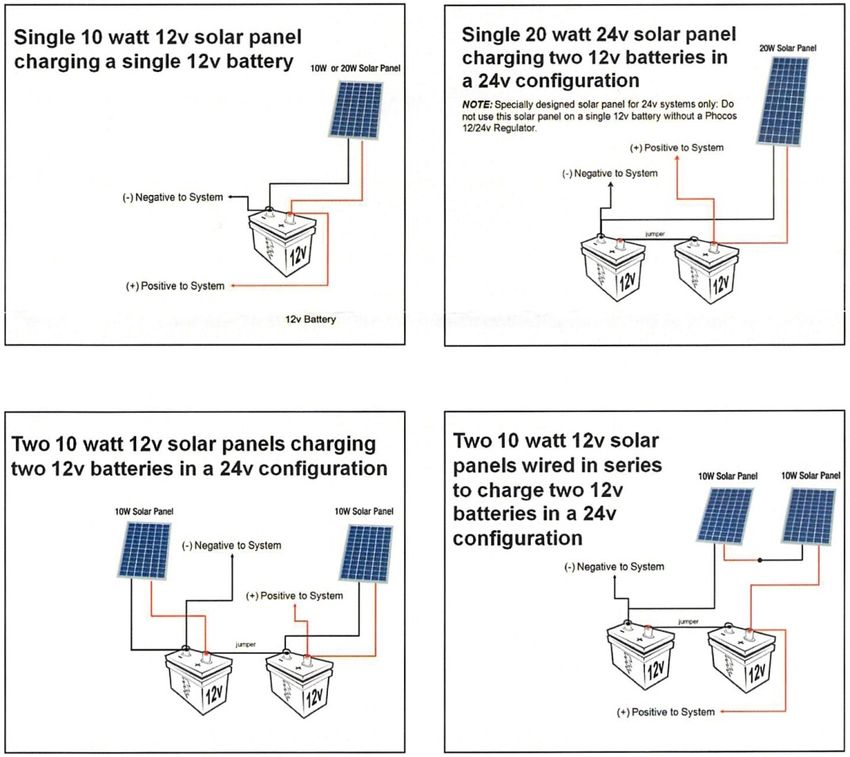
Programming Additional Remote – 12 Volt System (DC)
You may purchase additional hydraulic remote fobs from the dealer. You will need to program the
remote to work with your system. Locate the black receiver box attached to cover of the black box.
Remove the 4 small screws and remove the cover. Follow these instructions for new remote fobs or
existing remote fobs:

                                                               LED Light      Code Learning Switch

                                                                                           Page 9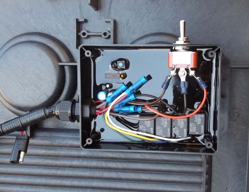
Adding Hydraulic Fluid
 When boat lift is completely lowered, there                                       Fill Hole Cap
 should be 1" to 1-1/2" of fluid in the tank. If
 there is less, additional fluid can be added to
 reach the recommended level in the tank.

 The tank will be at its maximum level when the
 lift is completely raised. Do not overfill the tank
 or the excess fluid will spill out of the tank
 through the cap.

 Use biodegradable hydraulic fluid. Contact
 your dealer for assistance in obtaining the
 correct hydraulic fluid. Factory hydraulic fluid
 is BioFlow AW-46.

 Flushing Hydraulic Fluid is recommended
 at least once every 24 months. See Pages
         18 – 19 for flushing details.

     Hydraulic Fluid BioFlow AW-46 is
                                                                      Fluid Tank
       available from your dealer.

Storage for the Off-Season                                    LED
The black hydraulic pump box is designed to be               Lights
disconnected for storage during the off-season. There will
be pressure in hydraulic hoses when the lift is in the raised
position. Lower the lift completely to remove the pressure.
Disconnect and roll the hoses. Do not allow the hoses to
touch the ground or dirt will stick to connectors. Carefully
move the hydraulic box to the storage area.

Do not disconnect hoses from pump while the system is
under load. The pressure in the hydraulic hoses will make
it difficult to connect the hoses again.

The weight in the box is not equally distributed -
Lift with caution!

Pier Pleasure's warranty does not cover wind, storm,
or ice damage. Do not leave any Pier Pleasure product
in the water during winter months. Any liability for
damages caused by leaving product in freezing water
will not be covered under warranty.

Page 10
Canopy Light – 12 Volt System (DC)
The hydraulic system isequipped with a 12 volt LED canopy light. The light plugs into the receiver
box. Install the light cord through the same hole in hydraulic box used for the hydraulic hoses.
Slide the 12 volt connections firmly together. Using plastic cable ties, attach the LED light to the
canopy frame in the desired location. The light can be operated using the remotes.
Page 11Solar Panel and Solar Panel Rod – 12 Volt (DC) (Optional)
The solar panel is available to charge the battery used 12 volt
hydraulic system. The solar panel will perform best if placed at
45 degree angle and facing direct south. If the charger does
not keep the battery charged, adjust the angle and direction for
maximum exposure to sunlight. The rod will allow the panel to
be rotated any direction.
Canopy Bracket for the
Solar Panel is also available.
Jumper Cable between the batteries on a 24 volt system is purchase separately.
Page 12Trouble Shooting
Trouble Remedy Page
Push remote button and X Check system shut-off switch. If switch is turned off, 6
nothing happens. the system will not operate.
X 12 volt battery low. Charge battery with battery charger. 6
X Check battery cable connections. 6
X If remote fob blue light does not flash - replace batteries 16
X Reprogram remote fobs - 12 Volt (DC) 9
Push remote button and X Use toggle switch inside box to raise lift. If toggle 7
lift bounces while raising lift. switch works properly, but remote causes the lift
to bounce, the 12 volt battery is low. Charge battery.
Remote will not work from X Battery low. Charge battery with battery charger. 7
a distance. X Signal between remote and antenna may be weak. 7
Move closer to hydraulic box.
Hydraulic fluid tank seems low. X When boat lift is completely lowered, there should be 10
1" to 1-1/2" of fluid in the tank. If there is less,
additional fluid can be added to reach the recommended
level in the tank. BioFlow AW46
Push button on remotes, X Hose couplers not completely tight. Use adjustable 5
pump runs, but will not move wrench to tighten couplers.
lift either up or down.
Hydraulic pump squeals and will X Pressure relief valve can be adjusted up. 17
not raise the boat completely. Factory Setting : 2700 psi
(Cylinder is not fully extended) Turning up pressure relief too high can cause damage
to the pump. Make only 1/8 to 1/4 turn and test.
When running the pump, the Valve / Coil is not shifting.
lift only goes down. X Hose couplers not completely tight. Use adjustable 5
wrench to tighten couplers.
X Check for loose wires.
X Check if coil is grabbing magnetically. If not, replace coil. 16
X Valve plugged : Remove valve, clean and replace 16
When running the pump, the Valve / Coil is not shifting
lift only goes up. X Hose couplers not completely tight. Use adjustable 5
wrench to tighten couplers.
X Check for loose wires.
X Check if coil is grabbing magnetically. If not, replace coil. 16
X Valve plugged : Remove valve, clean and replace 16
Page 14Trouble Shooting
Trouble Remedy Page
When running the pump to
lower the lift, the boat lift only
moves slightly, locks up
or stalls
X Check for loose wires.
X Check if coil is grabbing magnetically. If not, replace coil. 16
X Valves plugged : Remove valves, clean and replace 16
After raising lift up, the boat X Hydraulic system has debris in the system allowing
lowers back down leakage through the valves.
X A slow leak may be caused by debris in the valves. 16
Remove valves and clean thoroughly, replace and raise
boat lift back up. If leakage continues, a full system flush 18-19
may be required.
X A quick leak is caused by significant debris in the system 18-19
and will require a full system flush and complete cleaning of
both valves.
Canopy light is not working X Check cord connection. 12
Solar panel not charging battery. X Check wiring the wiring for the solar is connected to the 12
battery correctly.
X Solar panel must be facing to direct south at 45 degree 12
angle or adjusted to receive direct sunlight.
Page 15Remote Key Fob Battery
If the remote blue light does not flash when the remote fob
buttons are pressed, the battery may need to be replaced.
Remove the screw with a phillips screwdriver. The battery is
23A 12 volt battery.
Coil
Hydraulic Valves and Coils
Coil Problems
When operating the pump, the coils will
grab the valve magnetically. To test this,
remove the nut that is secured on top of the
coil. The coil will now be free to move up
and down on the valve. Hold the coil up on
the valve and then press the “up” or “down”
buttonon the remote. The coil will grab the
valve once the power begins to run. A
screwdriver on top and touching the valve
can also test the coil. Set a screwdriver on
top of the valve, press a remote button and
check if the screwdriver is grabbed
magnetically. Replace the coil if it is not
working properly.
Valve Problems
Debris can become lodged in the valves
causing leakage and performance
problems. The valves can be removed with
a wrench. Inspect the valves for damaged
o-rings, clogged ports and other possible
defects that could cause performance
problems. Clean with compressed air.
Watches, jewelry and other metal objects
that come in contact with electrical
system will spark and cause significant
injury. Always remove all jewelry and
shut off the system switch before
working inside the hydraulic box.
Page 16 ValvePressure Relief Adjustment
The pressure relief has a default setting of 2700 psi. In some cases, the pump may be set slightly lower
than 2700 psi. If the pump begins to squeal before the lift completely raised, the pressure relief may be
need to be increased. The squealing is the flow of fluid over the pressure relief under the load of the
boat. If you increase the relief pressure, the pump will raise the boat lift with the load of the boat.
To increase the relief pressure, use an1/8” Allen wrench to remove the cap over the pressure relief
valve (Photos 1 & 2). With a 3/16” Allen wrench, turn the valve 1/8 to 1/4 turn in clockwise (Photo 3).
Excessively turning relief
Do not turn more than ¼ turn without testing if system is working properly.Valve
valve pressure up will cause damage to the relief pressure valve and/or pump.
Access to relief valve adjustment is located on the back of the pump when the
pump is in the poly box. You may remove the pump from the box to make
adjusting easier. Photos of the pump and relief valve adjustment are shown
with pump removed from the black poly box.
Photo 1
Photo 1
Photo 2
Photo 2
Photo 3
Page 17Flushing the Hydraulic Fluid on a Hydraulic Boat Lift
A. Remove the boat from the boat lift and LOWER the lift completely to its lowest point.
B. Disconnect the hydraulic hose lines and remove the pump from the box.
Place the pump on a solid, stable surface. (Photo 1)
There are four
bolts that hold the
reservoir mounting
plate to the pump
housing. (The
fourth is hidden
from view)
Photo 1
C. Drain hydraulic reservoir by removing cap and pouring oil into a bucket or other suitable
container. Remove reservoir from pump. Your reservoir is held in place by four small bolts
in each corner of the mounting plate. (Photo1)
A small amount of mineral spirits or other solvent may be applied to a wiping cloth to loosen
stubborn dirt.
D. Reinstall reservoir on pump and fill approximately 1” from top of reservoir with clean
environmentally friendly hydraulic fluid. Factory hydraulic fluid is BioFlow AW-46
Flushing Hydraulic Fluid is recommended
at least once every 24 months.
Hydraulic Fluid BioFlow AW-46 is available
from your dealer.
Page 18E. Install the hydraulic line that RAISES the lift. This is the “female” coupler on the hose.
Install it on the “male” coupler on the pump. (Photos 2 & 3).
Male
Coupler Female Coupler on Hose
Female
Coupler
Photo 2 Photo 3
Photo 3
Male Coupler on Hose
Remove the male fitting from the
hose. Secure the end of the hose
tightly in a bucket as fluid under
pressure will cause the end of the Photo 4
hose to whip around erratically.
F. Remove the “male” coupler from the end of the hose that has not been reconnected.(Photo 4)
Then, secure the end of this hose in a bucket or other suitable container. NOTE: Fluid will be
under pressure in the next step. Secure the end of the hose, or have a helper hold the hose
tightly. The hose will whip around if it is not secured tightly!
G. Start raising the lift while watching the fluid level in the pump reservoir. You will have to add
hydraulic fluid as the lift is raised. When the lift has reached its fully raised position, reinstall the
male fitting on the hose. Remove the hose that is attached to the pump and put the pump back
in the box. Install both hoses on pump and run the lift all the way to the lowest point again, then
all the way to the top as a test. Recheck hydraulic fluid level and add fluid as necessary. Once
everything tests out properly, the boat may be installed back on the lift.
There should be about 1” of fluid in the tank when the lift is completely lowered.
Page 19Remote System Remote Fob System Shut-Off Switch
Part #: 542-REMOTE Part #: 542-REMOTE-PEND Part #: 542-SWITCH
Solenoid Part #: 542-25025 Coil Part #: 542-25000 Male Coupler
Part #: 542-21025
Lug Cover Terminal Protector Female Coupler
Part #: 542-26100B Part #: 542-26000 Part #: 542-21050
Part #: 542-26100R
Battery Cable
Part #: 542-BAT-CBL-BLK
Part #: 542-BAT-CBL-RED
Page 21PIER PLEASURE BOAT LIFT
LIMITED WARRANTY
During the term of the Limited Warranty on your Pier
Pleasure Boat Lift, Pier Pleasure’s obligations and
liabilities under this warranty are limited to covering the
cost of all parts and labor needed to repair or replace
any Pier Pleasure supplied item that proves defective Register your Pier Pleasure purchase at
in material, workmanship or factory preparation. These www.pierpleasure.com/warranty
repairs or replacements (parts and labor) will be made
by your dealer using new or remanufactured parts for What your Pier Pleasure Limited Warranty
the periods specified for each product as follows: Does Not Cover: Your Pier Pleasure Limited Warranty
does not cover the costs of repairing damage caused
by environmental factors or Acts of God.
“Environmental factors” include, but are not limited to,
such things as airborne fallout, chemicals, tree sap,
salt, brackish water, galvanic corrosion, electrolysis
and water hazards. “Acts of God” include, but are not
limited to, such things as rainstorms, hailstorms,
windstorms, tornadoes, lightning, f oods and
earthquakes.
Your Pier Pleasure Limited Warranty does not cover
ice damage. Do not leave any Pier Pleasure product in
or near the water during winter months. Leaving any
Pier Pleasure product in freezing water in all situations
is not recommended. ANY LIABILITY FOR DEFECTS
OR DAMAGES CAUSED BY LEAVING PRODUCT IN
FREEZING WATER WILL NOT BE COVERED
UNDER THIS WARRANTY.
Your Pier Pleasure Limited Warranty does not cover
the costs of repairing damage caused by poor or
improper maintenance. The Pier Pleasure Limited
Warranty does not cover the costs of normal or
scheduled maintenance of your aluminum Pier
Commencement of Warranty Pleasure Boat Lift.
The Pier Pleasure Limited Warranty will commence the
date the original owner takes delivery of a new Pier Your Pier Pleasure Limited Warranty does not cover
Pleasure Boat Lift. the costs of repairing damage or conditions caused by
f re or accident; by exceeding load ratings; by abuse or
Warranty not Transferable or Assignable: negligence; by misuse; by improper installation or
This Pier Pleasure Limited Warranty shall extend only removal; by tampering with parts; by improper
to the original owner of our product and is not adjustment or alteration; or by any changes made to
transferrable or assignable. The “original owner” is your Pier Pleasure Boat Lift that do not comply with
def ned as the f rst legal owner of a Pier Pleasure Boat Pier Pleasure specif cations.
Lift other than an authorized distributor or dealer who
has bought the boat lift from Pier Pleasure for resale to The Pier Pleasure Limited Warranty does not cover
the public. commercial use applications of any Pier Pleasure
product.Boat Lift Modification or Alteration: PURCHASE PRICE OF THE PARTICULAR
Unauthorized modif cations or alterations of, or use of PRODUCT AT ISSUE. SOME STATES DO NOT
components other than genuine Pier Pleasure ALLOW THE EXCLUSION OR LIMITATION OF
components, on any Pier Please products are not INCIDENTAL OR CONSEQUENTIAL DAMAGES, SO
recommended. ANY LIABILITY FOR DEFECTS OR THE ABOVE LIMITATION OR EXCLUSION MAY NOT
DAMAGES CAUSED BY SUCH UNAUTHORIZED APPLY TO YOU.
MODIFICATIONS OR ALTERATIONS OF, OR USE
OF COMPONENTS OTHER THAN GENUINE PIER THIS WARRANTY GIVES YOU SPECIFIC LEGAL
PLEASURE COMPONENTS, WILL NOT BE RIGHTS, AND YOU MAY ALSO HAVE OTHER
COVERED UNDER THIS WARRANTY. RIGHTS WHICH VARY FROM STATE TO STATE.
Production Changes: How to Get Warranty Service for Your Lift
Pier Pleasure and its distributors and dealers reserve Please contact the dealer from whom you bought the
the right to make changes in Pier Pleasure boat lifts boat lift for warranty service. When contacting your
built and or sold by them at any time without incurring dealer, please provide them with your date of purchase
any obligation to make the same or similar changes on and the nature of the problem. If contact with the
boat lifts previously built and or sold by them, including dealer is not feasible, please contact Pier Pleasure for
with regard to any warranty repairs or replacements further assistance.
and this Pier Pleasure Limited Warranty does not cover
the cost of adding anything to any Pier Pleasure Pier Pleasure reserves the right to have dealers
product once it is delivered to the original owner. conduct any necessary warranty service. Dealers and
Pier Pleasure, at their sole discretion, reserve the right
Disclaimers: to have defective parts returned for inspection as part
THE LIMITED WARRANTY SET FORTH HEREIN IS of the warranty claim process. Pier Pleasure does not
IN LIEU OF ALL OTHER WARRANTIES AND cover the cost of returning parts.
LIABILITIES WHETHER IN CONTRACT OR IN TORT,
NEGLIGENCE, EXPRESSED OR IMPLIED, IN LAW Thank you for the investment you have made in this
OR IN FACT, INCLUDING IMPLIED WARRANTIES Pier Pleasure product. This document contains Pier
OF MERCHANTABILITY AND FITNESS FOR A Pleasure, Inc.’s Limited Warranty. It should be kept in
PARTICULAR USE. SOME STATES DO NOT a safe place and presented to your dealer if any
ALLOW LIMITATIONS ON HOW LONG AN IMPLIED warranty service is needed.
WARRANTY LASTS, SO THE ABOVE LIMITATION
MAY NOT APPLY TO YOU.
Manufactured by:
TO THE MAXIMUM EXTENT PERMITTED BY LAW, Pier Pleasure, Inc.
PIER PLEASURE SHALL NOT BE LIABLE FOR ANY 1270 N River Drive
COSTS, LOSS, EXPENSE, DAMAGES, SPECIAL Mankato, MN 56001
DAMAGES, INCIDENTAL DAMAGES OR Phone 800.658.7010
CONSEQUENTIAL DAMAGES ARISING DIRECTLY www.pierpleasure.com January - 2018
OR INDIRECTLY FROM THE INSTALLATION, USE,
MISUSE, OR INABILITY TO USE THIS PRODUCT. All visual representations, dimensions, and
THIS EXCLUSION APPLIES REGARDLESS OF specifications contained in this manual are based
WHETHER SUCH DAMAGES ARE SOUGHT BASED on the latest product information available at time
ON BREACH OF WARRANTY, BREACH OF of publication approval. The right is reserved to
CONTRACT, NEGLIGENCE, STRICT LIABILITY IN make changes in material, equipment, design, and
TORT, OR ANY OTHER LEGAL THEORY. SHOULD specifications.
THE COMPANY NEVERTHELESS BE FOUND
LIABLE FOR ANY DAMAGES, THE TOTAL LIABILITY Register your Pier Pleasure purchase at
OF THE COMPANY SHALL BE LIMITED TO THE
www.pierpleasure.com/warrantyAll visual representations, dimensions, and specifications contained in this manual are based on the latest product information available at time of publication approval. The right is reserved to make changes in material, equipment, design, and specifications. Dock layouts shown in this manual may not meet local and state codes in your area. Pier Pleasure's warranty does not cover wind, storm, or ice damage. Do not leave any Pier Pleasure product in the water during winter months. Any liability for damages caused by leaving product in freezing water will not be covered under warranty.
You can also read