HYDROMATIC BOILER COMBINATION GAS & ELECTRIC - Model : GE3 RSA
←
→
Page content transcription
If your browser does not render page correctly, please read the page content below
HYDROMATIC BOILER
COMBINATION GAS & ELECTRIC
Model : GE3

                           RSA

Hansen Water Heaters
PO Box 35023 Northcliff
2115 South Africa
www.hansenproducts.co.za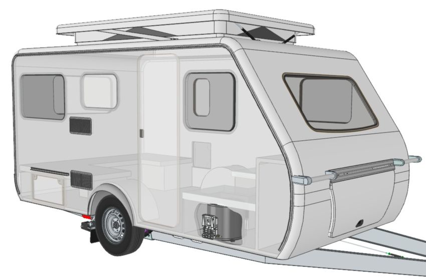
Table of contents                               Installation instructions

Symbols used                                3   Water heater kit                           8
General safety notes                        3   Choice of location                         8
Installation warnings                       3   Installation of water heater               8
Safe connecting of regulator to cylinder    4   Gas connection                             9
                                                Water connection                          10
                                                System installation …………………………………………………   10
Filling the water heater with water         4   Exploded view …………………………………………………………       11
Switching on gas operation                  4   Installation template                     12
Switching off gas operation                 4
Electrical operation ……………………………………………………   5
Maintenance                                 5
Fault finding                               5
Fuses                                       5
Technical data                              6
Hansen warranty policy                      7
Data label                                  8
Intended use                                8
Regulators                                  8

1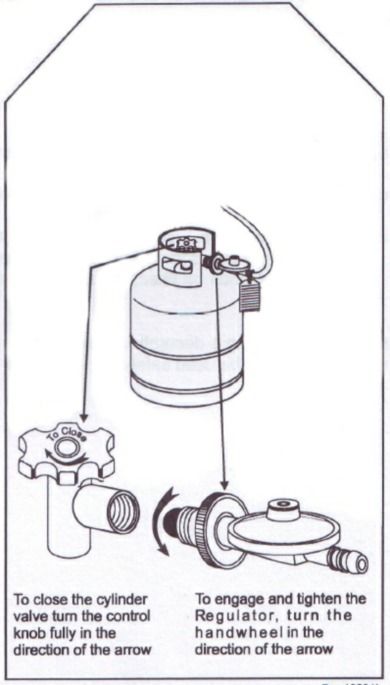
Safe connecting instructions of regulator to cylinder

    ● Before connecting the LPG regulator to the gas cylinder ensure that the rubber seal on the end of the regulator is in
      place and is in good working condition.

    ●

    ● Always make sure that the regulator is fully engaged with the cylinder valve threads and that the hand wheel is tight. Do
      not use excessive force.

    ● when connecting the cylinder always check for leaks by opening the cylinder valve and then apply soapy water solution
      to the joint between the cylinder valve and the regulator.

    ● If you find a leak, close the cylinder valve and contact an authorised LP gas dealer.

    ● When using the heater do not fully open the cylinder valve. Only open it 1 ½ turns to prevent the possible jamming of
      the cylinder valve in its open position.

    ● The      way to turn off a Roll-about heater is by closing the cylinder valve . To do this turn the cylinder valve control
      knob in an anti-clockwise direction .

    ● NEVER UNSCREW THE REGULATOR FROM THE CYLINDER VALVE WHILST THE CYLINDER VALVE IS OPEN OR IF
      THE HEATER IS ALIGHT.

            : Read these instructions for use carefully so as to familiarize yourself with the appliance before
connecting it to its gas container. Keep these instructions for future reference”.
- In the event of the burner burning-back, i.e. ignition under the burner cap or aeration adjustment switch off the
unit and contact your nearest LP gas dealer.

2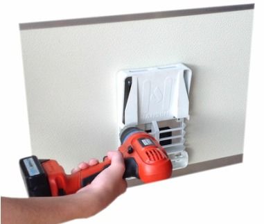
Symbols used                                                       Installation warnings

                                                                    ● This unit is to be installed in recreational vehicles only.
                                                                      Is to be installed on an exterior wall, with the flue open
                                                                      to the outdoors.
        Symbol indicates possible hazard
                                                                    ● All combustible air must be supplied from outside the
                                                                      recreational vehicle, and all products of combustion
        Important: pay attention !                                    must be vented to the outside of the RV.

                                                                    ● This appliance must be earthed. The manufacturer and
    ● If the information in this manual is not followed exactly,      seller do not accept responsibility for any damaged
      a fire or explosion could cause property damage,                due to incorrect electrical connection.
      personal injury or loss of life.                              ● Any discharge pipe connected to the safety pressure
    ● Do not store or use gasoline or other flammable                 valve is to be continuously downward direction and in
      vapours and liquids in the vicinity of this appliance.          a frost free ambient.
    ● Do not use matches, candles or other sources of               ● To be used         with a low pressure regulator 2,8 kPa
      ignition when checking for gas leaks.                           (SANS 1237).
    ● Shut off all gas appliances when refuelling.                  ● Do not vent the unit with a venting system servicing
    ● Do not operate when travelling.                                 another appliance.
    ● Do not operate when refuelling the vehicle and when           ● Do not vent the water heater to an outside enclosed
      in the garage.                                                  porch area.
    ● In the event of leaks in the gas system or if there is a      ● Do not modify the water heater in any way.
      smell of gas :                                                ● Do not alter the water heater for a positive grounding
       - Extinguish all naked flames                                  system.
       - Do not smoke
                                                                    ● Do not use a battery charger to supply power to the
       - Switch off all appliances
                                                                      water heater.
       - Shut of the gas cylinder
       - Open the windows and doors                                 ● Do not Hi-pot the water heater, unless the electronic
       - Do not switch on any electrical switches                     ignition has been disconnected.
       - Have the entire system checked by an expert!               ● Before gaining access to any and all terminals, please
    ● Use only LPG gas, do not use any other fuel.                    ensure all supply circuits are disconnected (I.e. 12 V)
                                                                      and the gas supply is securely turned off.
    ● This appliance may be installed only by a registered
      LPG gas installer.                                            ● Any work involving connection or wiring or inter
                                                                      connecting wiring must be connected by a licensed
    ● The use of upright gas cylinders from which gas is
                                                                      electrician.
      taken in the gas phase is mandatory for the operation
      of the gas regulators, gas equipment and gas systems.         ● Any modification to the unit, including accessories and
      Gas cylinders from which gas is taken in the liquid             cowl, or the use of spare parts and accessories that
      phase (e.g. for fork lifts) must not be used, since this        are important to the operation of the system that are
      would result in damage to the gas system.                       not original Hansen parts and failure to follow the
                                                                      installation and operating instructions will cancel the
    ● Repairs may only be carried out by an expert.
                                                                      warranty and indemnify Hansen from any liability
    ● This device is not designed to be used by persons               claims. It also becomes illegal to use the appliance and
      (including children) with limited physical, sensory or          in some countries this even makes it illegal to use the
      mental capacities or persons lacking in experience or           vehicle.
      know-how, unless they are supervised for their safety
                                                                    ● LPG Systems and the pressure regulators must comply
      or unless they have received instruction about how to
                                                                      with the administrative regulations of the country in
      use the device.
                                                                      which the appliance is used. For your own safety it is
    ● Children should be supervised to ensure they do not             absolutely necessary to have the complete gas
      play with the device.                                           installation regularly checked by an expert (at least
    ● To avoid the risk of accidental resetting of the over           every 2 years). the vehicle owner is always responsible
      temperature guard, the device may not be supplied               for arranging the gas inspection.
      with power via an external contractor, such as a timer,       ● Items sensitive to heat (e.g. spray cans) must not be
      nor may it be connected to a power circuit that is              stored in the installation area, since excess
      regularly switched on or off via a device.                      temperatures may under certain circumstances be
    ● The type or characteristics of the pressure control             incurred there.
      valve and expansion control valve (that may be                ● During the initial operation of a brand new appliance
      combined in one unit) and the details of the installation       or after it has been used for some time a slight smell
      must be understood.                                             of gas may be noticed for a short while.
    ● Flush the T&P valve occasionally to remove lime
      deposits. Continuous leakage from the valve may
      indicate a problem with the valve or over pressure
      from the water pump.
    ● Water may drip from the discharge pipe of the
      pressure relief safety valve, therefore the pipe must be
      left open to atmosphere.

3
Safe connecting of regulator to cylinder
                                                                 Residues of frozen water can prevent filling if there is frost.
                                                                 The water heater can be defrosted by switching on the
    ● Before connecting the LPG regulator to the gas
                                                                 water heater for short period (max 2 minutes). Frozen
      cylinder ensure that the rubber seal on the end of the
                                                                 pipes can be defrosted by heating the room.
      regulator is in place and is in good working condition.
    ● The cylinder hand-wheel must be turned in an
      anticlockwise direction (when facing the cylinder valve          If just the cold water system is being used, without
      thread opening) to engage the regulator thread                   water heater, the heater tank is also filled up with
      correctly into the cylinder valve.                               water. In order to avoid damage through frost the
                                                                 water contents must be drained by the drain valve, also
    ● Always make sure that the regulator is fully engaged
                                                                 when the heater is not being used. A an alternative, two
      with the cylinder valves threads and that the hand
                                                                 shut-off valves, resistant to hot water, can be fitted in front
      wheel is tight. Hand tighten only. Do not use excessive
                                                                 of the cold and hot water connection.
      force.
    ● When connecting the cylinder, always check for leaks
      by opening the cylinder valve then applying soapy
      water solution to the point between the cylinder valve
      and the regulator.                                         1. Disconnect power for water pump (main switch or pump
    ● If you find a leak, close the cylinder valve and contact   switch).
      and authorized LPG dealer.
                                                                 2. Open hot water taps in bathroom and kitchen
    ● Do not fully open the cylinder valve, only open it 1 ½
                                                                 3. Open the drain valve
      turns to prevent the possible jamming of the cylinder
                                                                 4. The water heater is now drained directly to the outside
      valve in its open position.
                                                                 via the drain valve. Check that the water contents have
    ● Never unscrew the regulator from the cylinder valve        been completely drained (14 litres).
      whilst the cylinder valve is open.

                                                                 Switching on gas operation
Operating instructions
                                                                  ● Ensure the gas supply bottle is full and opened
Always observe the operating instructions prior to starting
The vehicle owner is responsible for the correct operation        ● Select gas mode on the switch control panel
of the appliance.                                                 ● Switch to the on position
                                                                  ● Led mode - (Slow) flashing - unit in start up mode
                                                                  ● Led mode - (Solid) gas burner is on & heating water
Before using the water heater for the 1st time it is essential    ● Led mode - (Fast) flashing burner- failed to start
to flush water supply through with clean water. Always fit        ● Led mode - (Off) standby - water hot
the flue outside cover when the water heater is not being
operated. Drain the water heater if there is a risk of frost.
There shall be no claims under guarantee for damage              Water should reach set temperature 65°c in
caused by frost or freezing!                                     approximately 35 minutes.

Always remove the flue outside cover prior to operating
the water heater!                                                Switching off gas operation

If connected to a central water supply (rural or city            Switch off the water heater to off position on the control
connection) or using more powerfully pumps, a pressure           panel.
reducing valve must be used which prevents pressures of
greater than 200 kPa occurring in the water heater.              If the water heater is not to be used for a long period,
                                                                 mount the flue cover (non observance of this point can
Filling the water heater with water                              lead to the function of the appliance being impaired
                                                                 through water, dirt or insects, close the gas supply line and
                                                                 the gas cylinder.
1. Check that the drain valve on the cold water intake is
closed. The lever should be in the closed position.
                                                                       Before setting off on any journey, fit the flue cover
                                                                       with the water heater switched off. please ensure
2. Open any hot tap in the bathroom or kitchen, mixing                 that it is secure and has locked into place. Defective
taps set to the hot position.                                    flue cover must not be used

3. Switch on power for the water pump.

Leave the tap open to let air escape while the water heater
tank is filling. The heater is filled when water flows out of
the tap.

4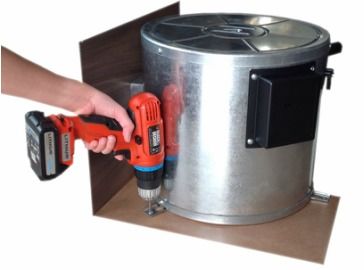
Electrical operation                                           Fault Finding

               Operate the water heater without water in it    Gas operation

    ● Ensure AC power supply is present
                                                               When switching on , the       - No 12 v supply
    ● Switch electric mode on the switch panel.
                                                               heater does not operate
    ● Switch to the on position on the switch control panel.
    ● Led mode - (solid) electric element on heating water.
                                                               Check the power supply (operation voltage min 10.5 V)
    ● Led mode - (off) Standby - water hot.                    Check the control board fuse

Maintenance                                                    When switching on the         - Cowl cover fitted
                                                               heater does not operate       - Air in the gas supply
                                                               and the red lamp lights up    - No gas supply
Use wine vinegar into the appliance via the water supply.
                                                               after approximately 30        - Incorrect gas pressure
Allowing the product to react and then thoroughly flush
                                                               seconds.
out the appliance with plenty of fresh water. To sterilise
the water we recommend "Certisil-Argento". Other
products, particularly those containing chlorine are           Remove flue cover and or clear any obstruction.
unsuitable.                                                    Check gas valves and gas bottle
                                                               To unlock (and purge air), switch off the appliance, wait
                                                               5 minutes, and switch on again
In order to avoid the colonization of micro-organisms, heat
up the water heater to 70°c at regular intervals.
                                                               Heater operates for a long - Over temperature
                                                               time and then the red lamp thermostat operated.
Fuses                                                          lights up.

The control board has a 2 amp mini type blade fuse. This
                                                               Check water contend, refill if required (close drain valve).
should only be replaced with a fuse of the same rating.
                                                               To unlock, switch off the appliance, wait 5 minutes and
                                                               switch on again.

                                                               Electrical operation

                                                               When switching on the         - No 240 V supply voltage
                                                               water heaters does not        - Over temperature
                                                               operate.                      thermostat operated

                                                               Connect the van to the sites supply and or check residual
                                                               current circuit breaker.
                                                               Check water content, refill if required ( close drain valve).

                                                               The electrical heating element is fitted with an excess
                                                               temperature cut out. In the event of a fault, switch off at
                                                               the control panel wait 10 minutes then switch on again.

                                                               Water supply

                                                               Water drips from the          - Water pressure from
                                                               safety valve                  supply pump to high

                                                               Check pump pressure (max. 200 kPa), use a pressure
                                                               reducing valve connected to the central supply.

                                                               When opening the cold         - Hot water flows back
                                                               water tap, hot water          through the cold supply
                                                               comes out

                                                               Fit a non-return valve in the cold water supply (refer to
                                                               installation instruction).

5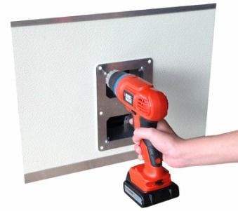
Technical data

Manufacturer
Hansen water heaters Pty Ltd
PO 35023 Northcliff
Johannesburg
South Africa

14 Litres

Max. 280 kPa

Max. 300 kPa

Liquid propane gas LPG

2.75 kPa

5.0 MJ/h

1.5 kW

120 g/h

0.70 mm
              15°c up to 70°c approx.)
Gas operation approx 35 min

Electric operation approx 35 min

Ignition : 0.18 A
Heating up : 0.08 A
Standby : 0.04 A

Heating up 4.3 A 1000 W

Approx 6.5 kg

Unit Dimensions

                                         All dimensions in mm

6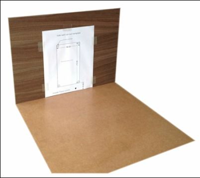
Hansen warranty policy                                        Warranty does not cover

The warranty is given by                                      Any water heater which has been :

Hansen water heaters Pty Ltd                                  - Subject to misuse, neglect, accident or alteration by any
PO Box 35023                                                  person.
Northcliff
2115                                                          Damaged or destroyed by fire, flood, act of God or other
Johannesburg                                                  inevitable accident.
South Africa
                                                              - Fair wear and tear
For 12 months from the date of purchase against any defect
arising from faulty materials or workmanship.                 - Damage from foreign substance such as dirt or liquid

Repairs will be carried out during normal business hours      - Travelling expenses or call out fee to and from authorised
only by Hansen Water heaters or its duly authorised service   service agents premises.
agents, and are subject to the warranty conditions and
exclusion hereunder.                                          - Accommodation or site expenses.

                                                              - Cleaning of the system or cleaning and adjustment of the
                                                              gas system. This is considered to be normal product
- The company will only provide service on presentation       maintenance.
of proof of purchase, on either the Hansen products, or the
caravan / RV / craft in which the Hansen product has been     - Non operation of the water heater or resultant damage
installed, to any authorised service agent. The purchaser     to the unit where the water heater has been operated in
must allow the service agent to photocopy the proof of        an out of level situation.
purchase to facilitate his claim to the manufacturer
                                                              - Freight cost of the appliance or parts, to or from, point
- Warranty repairs can only be performed by authorised        of service or transit damage.
service agents and under no circumstances will Hansen
reimburse repairs carried out by unauthorised persons.        - Hansen are not responsible for the resultant loss or
Tampering with any part of the product by unauthorised        damage sustained by the purchaser.
personnel will automatically voids the warranty.
                                                              - Non operation of the appliance or resultant damage to
- The product must be used solely for domestic and or the     the unit where the appliance has not been installed,
purpose in which its designed for. Commercial purposes        ventilated, flue or operated in accordance with the
the warranty is 6 months only.                                manufacturers instructions.

- Where applicable, the products must be used on the          Apart from any warranties implied by the Trade practices
appropriate electrical voltage, gas type and pressure, or     act 1974 or any relevant state legislation all other
fuel source.                                                  warranties express or implied weather arising by virtue of
                                                              saute or otherwise are hereby excluded.
- If at any time during the warranty period any parts are
replaced with a part or parts not supplied or approved by
Hansen, this warranty shall immediately become void.

7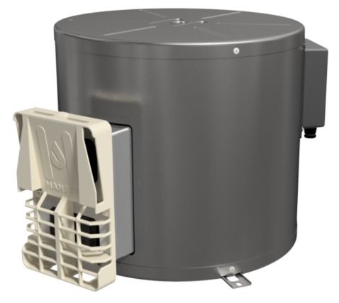
Installation instructions                                    Choice of location

                                                                  1. Always install the appliance in such away that it
                                                                  is easily accessible for service work at all times
This appliance shall be installed in accordance with the          and can be easily removed and installed
manufacturers installation instructions, local gas fitting
regulations, municipal building codes, electrical wiring     2. Locate the heater in such a way that the cowl can be
regulations, AS 5601 "Gas installations" and other           mounted on the outside on a surface which is a straight
statutory regulations and water supply regulations.          and smooth as possible. This outsides surface must be
                                                             exposed to wind from all directions and, if possible,
                                                             there should be no trim strips or covers in this area.
Data label                                                   Mount the water heater on an appropriate base if
                                                             necessary to ensure its level.
The data label is located on electric cover of the water
heater.                                                      The cowl must be placed in such a way that the exhaust
                                                             gas cannot find its way into the vehicle interior. For this
This appliance is suitable for propane gas only, ensure      reason, choose a location where there are no opening
that the available gas supply is suitable.                   windows, sky lights or ventilation openings directly
                                                             above the cowl or for or for 50 cm on either side. If this
                                                             is not possible, a warning plate must be placed on the
                                                             inside of the window (or skylight) stating that it must
Intended use                                                 be kept closed while the heater is operating. In this case
                                                             refrigerator ventilation's must be tight sealed from the
This appliance has been designed for the installation in     interior of the vehicle
caravans, mobile homes and other vehicles. It is not
approved for installation in boats. Other forms of use       Installation of the water heater
are also possible following consultation with Hansen.
                                                              1. Use the template provided in this manual (Pg12).
                                                             Position template on the inside of the side wall.
Regulations
                                                             2. Drill 4 holes in each corner 10 mm diameter through
Any modifications to the unit, including accessories and     the wall on the markings shown.
cowl, or the use of spare parts and accessories that are
important to the operation of the system that are not        3. Saw the cut-out section for cowl 96 x 172 mm
original Hansen parts and failure to follow the
installation and operating instructions will cancel the      If there are any cavities in the area of the cowl, pack
warranty and indemnify Hansen from any liability claims.     these with pieces of wood so as to be able to tighten
It also becomes illegal to use the appliances, and in        the screws.
some countries this even makes it illegal to use the
vehicle.                                                     The finished hole should be 172 mm high and 96 mm
                                                             wide 33 mm above the inside floor level.
The operating pressure for the gas supply is 2.75 kPa
and must correspond to the operating pressure of the
appliance (see data plate).

After it has been installed, the device must be
disconnected from the power supply. It can be
disconnected by ensuring that the power plug is
accessible or by installing a switch in the fixed power
supply installation.

When installing the appliance always observe the
technical and administrative rules and regulations of the
country in which the vehicle is to be registered, for the
1st time!

Water heater kit

The water heater kit contains :
Wall sealing plate & 6 x 25mm screws
Flue travel cover
Flue grill
Foot insulators & 3 x 25mm screws
Water straight fitting x 2

8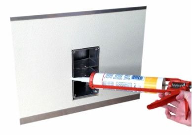
3. Connect the LPG gas supply pipe to the water heater. 5. Fasten sealing frame plate to the cowl body using
Only use suitable approved gas supply pipe. Fit the 4 self cutting screws.
pipe onto the hose barb and secure using a hose clamp.
6. Mount the grille. Press the entire cowl assembly
onto the vehicle wall and fasten with 6 screws.
4. Position the water heater through the cut out opening.
7. Screw the water heater secularly to the floor of the
vehicle with at least two shackle plates with the
screws provided 5.5 x 25, on suitable base (plywood
panel, laminated wood strips or metal base.
4. Remove sealing frame and coat with non hardening
mastic on the side facing the vehicle - do not use
silicone
Installation of the water connectors
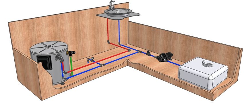
9System installation Legend
1 - Water heater
2 - Safety temperature and pressure valve
3 - Drain valve (Not supplied. Sold separately)
4 - Mixer tap
5 - Pressure reducing valve
6 - Water pump
7 - Main water supply tank
4
1
2 5 6
3 7
Installation of the safety temperature and
Water pipe routing
pressure valve
Connection for the cold water supply between the water
pump (6) and inlet on the water heater (8), a drain valve
The safety temperature and pressure valve come factory maybe fitted in-line as indicted (3).
pre-fitted on the water heater Connection for the hot water supply between the tap (4)
and outlet on the water heater (8)
Drain pipe on the T&P valve (2) fitted through the floor
to outside atmosphere.
All pressure and submersible water pumps be used for
operating the water heater.
In order to guarantee complete emptying of the
water content and to prevent pressure greater than
300 kPa occurring in the water heater, the safety
temperature and safety valve MUST be used.
The supplied water connectors safety drain valve have a
12 mm rigid piping connection (e.g. John Guest system).
For connecting to rigid pipes with other diameters
appropriate adapter must be used.
Route the pipes so that they are as short and free of
kinks as possible (hose connections must be secured
using hose clamps - also for cold water! - pressure
of up to 300 kPa can occur in the T&P safety valve - also
with the submersible pumps - because of the heat of the
water and resulting expansion.
All hot water pipes should be routed in a descending
manner to the safety valve ! Otherwise no guarantee
of frost protection
101 Water tank
2 Silicone sealant
3 Outer container 6
4 Base cover
5 Outer cover
6 Top cover
7 Gas burner
8 Burner mount
9 Flame Sense electrode
10 Spark electrode
11 Intake cowl 5
12 Heating element
13 Water fittings
14 Water fittings boss
15 T&P valve boss
16 T&P safety valve
17 Gas valve assembly
18 Flue intake casting
19 Wall sealing plate 22
20 Flue grill
22
21 Electric cover 16
15 1 13
22 O ring 14
23 Electronic control board
12
9
10
7
8
2
11 21
23
3
20 19 18 17
4
11Drill hole markings
Dimensions shown in mm
Inside Floor Level
12You can also read