Owner's Guide Installation & Operation - Upright Convection Oven
←
→
Page content transcription
If your browser does not render page correctly, please read the page content below
Owner’s Guide
                                                 Installation & Operation
Upright Convection Oven
HUCO Series

                                   Hestan Commercial Corporation
                                       3375 E. La Palma Ave
                                        Anaheim, CA 92806
                                           (888) 905-7463
                          RETAIN THIS MANUAL FOR FUTURE REFERENCE

                                                                    P/N 026267 REV C

©2021 Hestan Commercial                     1                        HUCO Series
IMPORTANT FOR YOUR SAFETY
THIS MANUAL HAS BEEN PREPARED FOR PERSONNEL QUALIFIED TO INSTALL
GAS EQUIPMENT, WHO SHOULD PERFORM THE INITIAL FIELD START-UP AND
ADJUSTMENTS OF THE EQUIPMENT COVERED BY THIS MANUAL.
POST IN A PROMINENT LOCATION THE INSTRUCTIONS TO BE FOLLOWED IN
THE EVENT THE SMELL OF GAS IS DETECTED. THIS INFORMATION CAN BE
OBTAINED FROM THE LOCAL GAS SUPPLIER.
IMPORTANT
IN THE EVENT A GAS ODOR IS DETECTED, SHUT DOWN UNITS AT MAIN
SHUTOFF VALVE AND CONTACT THE LOCAL GAS COMPANY OR GAS SUPPLIER
FOR SERVICE.
FOR YOUR SAFETY
DO NOT STORE OR USE GASOLINE OR OTHER FLAMMABLE VAPORS OR
LIQUIDS IN THE VICINITY OF THIS OR ANY OTHER APPLIANCE.
WARNING
IMPROPER INSTALLATION, ADJUSTMENT, ALTERATION, SERVICE OR
MAINTENANCE CAN CAUSE PROPERTY DAMAGE, INJURY OR DEATH. READ
THE INSTALLATION, OPERATING AND MAINTENANCE INSTRUCTIONS
THOROUGHLY BEFORE INSTALLING OR SERVICING THIS EQUIPMENT.
IN THE EVENT OF A POWER FAILURE, DO NOT ATTEMPT TO OPERATE THIS
DEVICE.
CALIFORNIA PROPOSITION 65 - WARNING
WARNING This product can expose you to chemicals including carbon monoxide, which is known to the
State of California to cause cancer.
For more information, go to www.P65Warnings.ca.gov.
©2021 Hestan Commercial 2 HUCO SeriesContents
Installation....................................................................................................................................... 4
Installation Procedure.......................................................................................................................... 4
Safe Handling .......................................................................................................................... 4
Uncrating ................................................................................................................................. 4
Location ................................................................................................................................... 4
Clearances ................................................................................................................................ 4
Assembly, Single Oven ............................................................................................................ 4
Assembly, Double Oven .......................................................................................................... 5
Leveling: .................................................................................................................................. 5
Statutory Regulations (Install Codes).................................................................................................. 5
Connections ......................................................................................................................................... 6
Oven Gas Requirement ............................................................................................................ 6
Gas Supply ............................................................................................................................... 6
Gas Supply Notes..................................................................................................................... 6
Flexible Coupling, Connectors and Casters ............................................................................. 6
Gas Pressure Regulator ............................................................................................................ 7
Factory Adjusted System ......................................................................................................... 7
Checking for Leaks .................................................................................................................. 7
Air Supply & Ventilation ......................................................................................................... 8
Electrical Connection:.............................................................................................................. 8
Model / Serial / Rating Plate Locations ................................................................................... 8
Lighting Instructions ................................................................................................................ 9
Final Preparation ...................................................................................................................... 9
Operating Instructions ................................................................................................................... 10
Controls ............................................................................................................................................. 10
Normal Use ....................................................................................................................................... 10
End Of Day Shutdown ........................................................................................................... 10
Cleaning and Maintenance ............................................................................................................ 10
Daily Cleaning ....................................................................................................................... 11
Periodic Cleaning................................................................................................................... 11
Stainless Steel ........................................................................................................................ 11
Service............................................................................................................................................11
©2021 Hestan Commercial 3 HUCO SeriesInstallation
Installation Procedure
Safe Handling
DO NOT USE door to lift or move oven!
All ovens must be installed on legs or casters supplied with the oven(s). Single ovens require the extended legs stand
plus legs or casters.
The appliance is heavy. Make sure you have proper equipment and enough people to safely move, assemble, and
place the oven.
Uncrating
Check the crate for any possible damage sustained during transit.
Carefully remove the appliance, removing all packing material,
and
again check for damage. Any damage to the appliance must be
20 s crewest s
reported to the carrier immediately. 1/ 4-s - f our s
nut
Location
Proper placement of the appliance will ensure operator convenience
and satisfactory performance. Adequate clearance must be
maintained so that the combustion and ventilation air is not
obstructed for proper operation.
The oven must not be mounted on a curb base. It must be mounted
on the casters or legs provided.
A minimum front clearance of 36 inches (914 mm) must be
provided for servicing. The appliance must be kept free and clear of
combustible materials.
Clearances
The following minimum clearances must be followed:
COMBUSTIBLE NON-COMBUSTIBLE
MODEL Back Side Back Side
HUCO series 6” 6” 0” 0”
Assembly, Single Oven
A single oven requires the extended legs stand plus legs or casters.
1) If legs will be used, mount the legs to the extended legs stand.
2) If casters will be used:
a. Identify the front side of the extended legs stand.
b. Install locking casters to front of extended legs stand.
c. Install non-locking casters to rear of extended legs stand.
d. Ensure extended legs are immobile.
3) Mount oven to extended legs stand.
©2021 Hestan Commercial 4 HUCO SeriesAssembly, Double Oven
1) If casters will be used:
a. install locking casters to front of oven
b. Install non-locking casters to rear of oven
2) If legs will be used, assemble provided legs to bottom oven.
3) Ensure casters will not roll, then set top oven on bottom oven,
4) Secure units to each other at rear with two ¼-20 nuts and bolts on each side, as shown in the figure.
5) For units that are already stacked, follow steps 1 and 2.
Caster installation notes
If casters are provided, match holes on the caster with holes on the oven bottom base or extended legs stand and
fasten with bolts provided. NOTE: Locking type casters mount on the front side of oven.
Leveling:
A carpenter’s spirit level should be placed on the oven’s center baking rack and the unit leveled both front-to-back
and side-to- side. If it is not level, cakes, casseroles, and any other liquid or semi-liquid batter will not bake evenly,
burner combustion may be erratic, and the unit will not function efficiently.
If the floor is relatively smooth and level, the unit may be further leveled with adjustment in the foot of the leg.
Units with casters must be leveled with shims. A unit will probably not return to the same position after being
moved, requiring re-leveling after each and every move.
Statutory Regulations (Install Codes)
The installation of this appliance must be carried out by a properly trained and qualified installer and in accordance
with the relevant regulations, codes of practice and the related publications of the Country, State, County and City of
destination.
United States of America
Installation must conform with local codes, or in the absence of local codes, with the National Fuel Gas Code, ANSI
Z-223.1 (latest edition.).
Electrical wiring from the electric meter, main control box or service outlet to appliance must be electrically
grounded in accordance with local codes or in the absence of local codes, with National Electrical Codes ANSI/NFPA
70 – current
Canada
Installation should conform to installation codes for gas burning appliances and equipment standard CAN1-B149.1
(Natural. gas) or CAN1-B149.2 (Propane gas).
Electrical wiring from the Electric Meter, main control box or service outlet to appliance must be electrically
grounded in accordance with local codes or in the absence of local codes, in Canada, conform to Canadian Electrical
Code CSA-C22.1
Resources
American Gas Association, Inc.: http://www.aga.org/
National Fire Protection Association: http://www.nfpa.org/
CSA: http://www.csa.ca
©2021 Hestan Commercial 5 HUCO SeriesConnections
Oven Gas Requirement
Single oven requires one gas connection, Double oven requires two gas connections.
The gas supply (service) line must be the same size or greater than the inlet line of appliance. The HUCO series
ovens use a ¾” NPT inlet. Sealant on all pipe joints must be resistant to LP gas.
Gas Supply
The local gas authority should be consulted at the installation planning stage in order to establish the availability of
an adequate supply of gas and to ensure that the meter is adequate for the required flow rate. The pipe work from the
meter to the appliance must be an appropriate size.
Manual Shut-Off Valve
All fixed (non-mobile) appliances must be fitted with an accessible upstream gas shutoff valve as a means of
isolating the appliance for emergency shut off and for servicing. A union or similar means of disconnection must be
provided between the gas-cock and the appliance.
Kitchen Shut-Off Valve
A manually operable valve must be fitted to the gas supply to the kitchen to enable it to be isolated in an emergency.
Wherever practical, this shall be located either outside the kitchen or near an exit in a readily accessible position.
Where it is not practical to do this, an automatic isolation valve system should be fitted which can be
operated from a readily accessible position near the exit.
In locations where the manual isolation valve is fitted or the automatic system can be reset this notice must be
posted:
“ALL DOWNSTREAM BURNER AND PILOT VALVES MUST BE TURNED OFF
PRIOR TO ATTEMPTING TO RESTORE THE SUPPLY. AFTER EXTENDED SHUT
OFF, PURGE BEFORE RESTORING GAS”
Gas Supply Notes
1) The type of gas for which the unit is equipped is stamped on the rating plate; see Model / Serial / Rating
Plate Locations on page 8. Connect a unit stamped “NAT” only to natural gas and stamped “LP” only to
propane gas.
2) If it is a new installation, have the gas authorities check the meter size and piping to assure that the unit(s)
is supplied with the necessary amount of gas supply and pressure to operate the unit(s).
3) Make certain new piping and connections have been made in a clean manner and have been purged so that
piping compound, chips, etc. will not clog pilots, valves, gas regulator, or burners. All connections must be
sealed with a joint compound suitable for LP gas.
Flexible Coupling, Connectors and Casters
If the unit is to be installed with flexible couplings and /or quick-disconnect fittings, the installer must use an AGA
design-certified commercial flexible connector of at least ¾” NPT (with suitable strain relief). The flexible
connector must comply with the standard for Connectors for Movable Gas Appliances, ANSI Z21.69 and
addendum Z21.69a (or latest edition), and a quick-disconnect device that complies with the standard for quick-
disconnect devices for use with Gas Fuel should comply with ANSI Z21.41/CSA 6.9 and addendum Z21.41a (or
latest edition). If disconnection of the restraint is necessary, make sure to reconnect restraint after the appliance has
been returned to its originally installed position.
Domestic gas or water connectors are not suitable!
Restraining device may be attached to the back frame/panel of unit.
If the unit is to be installed with casters, a flexible connector must be used and the same ANSI standard applies.
Locking front casters are provided to limit the movement of the appliance without depending on the connector or
associated piping. A suitable strain relief must be installed with the flexible connector.
All connections must be sealed with a joint compound suitable for LP gas and all connections must be tested with a
soapy water solution before lighting pilots or attempting use.
©2021 Hestan Commercial 6 HUCO SeriesGas Pressure Regulator
All commercial cooking equipment must have a pressure regulator on the incoming service line for safe and efficient
operation, since service pressure may fluctuate with local demand. The pressure regulator comes with the oven.
Failure to install the pressure regulator will void the equipment warranty!
The regulators supplied with Hestan Upright Convection Ovens have ¾” inlet /outlet ports and are adjusted at the
factory for 5” WC (Natural gas) or 10” WC (Propane gas) depending on customer’s ordering instructions.
1) Prior to connecting the regulator, check the incoming line pressure, as these regulators can only withstand a
maximum pressure of ½ PSI (14”WC).
2) If the line pressure is beyond this limit, a step-down regulator will be required.
The arrow shown on the bottom of the regulator body shows gas flow direction; it should point downstream to the
appliance. The red air vent cap on the top regulator is part of the regulator and should not be removed.
Any adjustments to regulators must be made only by qualified service personnel with the proper equipment.
NOTE: Gas pressure should be checked when the unit is installed and all other equipment on the same line is on.
The operating gas pressure must be the same as that specified on the rating plate
The appliance and its individual shutoff valve must be disconnected from the gas supply piping system
during any pressure testing of that system where pressures are in excess of .5 psig (3.45kpa).
When test pressures are .5 psig (3.45kpa) or less, the appliance must be isolated from the gas supply system
by closing its individual manual shutoff valve.
Factory Adjusted System
All Hestan appliances are adjusted and tested before leaving the factory, effectively matching them to sea level
conditions. Adjustments and calibrations to assure proper operation may be necessary on installation to meet local
conditions; low gas characteristics, to correct possible problems caused by rough handling or vibration during
shipment and are to be performed only by qualified service personnel. These adjustments are the responsibility of
the customer and/or dealer and are not covered by our warranty.
Checking for Leaks
CAUTION: When checking for leaks, do not stand with your face close to the combustion chamber.
Check all gas connections for leaks with a soapy water solution before lighting any pilots or attempting operation.
DO NOT USE AN OPEN FLAME TO CHECK FOR LEAKS!
Putting an open flame beside a new gas connection is extremely dangerous.
Prior to lighting, check all joints in the gas supply line for leaks. Use soap
and water solution. Do not use an open flame. After piping has been checked
for leaks, all piping receiving gas should be fully purged to remove air.
©2021 Hestan Commercial 7 HUCO SeriesAir Supply & Ventilation
The following notes are intended to give general guidance. For detailed recommendations, refer to the applicable
codes in the Country, State, County and City of installation.
Do not obstruct the flow of combustion and ventilation air.
Proper ventilation is critical for optimum performance. The area in front of, around and above the appliance must be
kept clear to avoid any obstruction of the flow of combustion and ventilation air. Adequate clearance must be
maintained at all times in front and at the sides of the appliances for Servicing and proper operation.
The ideal method of ventilating gas fired equipment is the use of properly designed canopy that should extend six
inches (152mm) beyond all sides of the appliance (s) and six feet six inches (1981mm) above the floor. Information
on the construction and installation of ventilating hoods may be obtained from the standard for "Vapor Removal
from Cooking Equipment," NFPA No. 96 (latest edition), available from the National Fire Protection Association,
on their web site: http://www.nfpa.org/.
A strong exhaust will create a vacuum in the room. For an exhaust vent to work properly, replacement air must be
equal to the amount of air exhausted. An imbalance between exhaust and replacement air can cause degradation in
the appliance’s performance. Strong exhaust fans in this hood or in the overall air conditioning system can produce a
slight vacuum in the room and/or cause air drafts, either of which can interfere with pilot or burner performance and
can also be hard to diagnose. Air movement should be checked during installation; if pilot or burner outage problems
persist, make-up air openings or baffles may have to be provided in the room.
NOTICE: In the Commonwealth of Massachusetts all gas appliances vented by either mechanical systems or
ventilation hoods shall comply with 248 CMR interlocking requirements.
Electrical Connection:
The Hestan Convection Oven requires a 120 volt supply to operate the ignition system and blower. The supply cord
provided along with the appliance is equipped with a three prong (grounding) plug for protection against shock
hazard.
This appliance must be electrically grounded in accordance with applicable
codes
The electrical service must be equipped with a properly grounded three prong receptacle, in accordance with local
codes, or in the absence of local codes, with the national electrical code, ANSI/NFPA 70-1987. In Canada, conform
to Canadian electrical codes, CSA-C22.1.
Do not cut or remove the grounding prong from this plug. Wiring diagram is located on the backside of the
appliance.
Disconnect power supply before cleaning or servicing.
NOTE: This appliance is not capable of being operated in the event of power failure. No
attempt should be made to operate this appliance during power failure.
Model / Serial / Rating Plate Locations
The rating plate is located on the back of the oven near the top left (as facing the back).
©2021 Hestan Commercial 8 HUCO SeriesLighting Instructions
1) At initial startup, turn the thermostat dial to the “OFF” position. Place the power switch to the “OFF”
position.
2) Wait five minutes.
3) Place power switch to the “ON” position. Turn the oven thermostat to the desired temperature. Confirm that
the fan runs and BURNER ON illuminates.
4) For a complete shutdown, place the thermostat and power switch in the “OFF” position.
TO CHECK FOR GAS LEAKS
1) Remove the kick plate and the component cover at the rear of the oven
2) Check pilot tubing and burner tubing for leaks at the connectors with a soapy water solution.
3) Turn the thermostat to any setting and the burner should light.
4) Check the burner orifice elbow connection downstream of the valve with a soapy water solution.
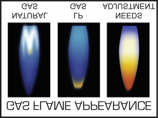
5) Check the burner visually for blue flame. See the figure below for proper flame appearance. For NG, there
should be no yellow tips or soot. For LP, small yellow tips are normal. If the flame doesn’t burn as shown,
shut down the appliance and call an authorized service person to adjust the burner air shutter.
Final Preparation
On initial installation, do the following:
1) Turn the oven to 250 degrees and operate for about 1 hour
2) Adjust the thermostat to its maximum and operate for another hour.
This will drive off solvents remaining in the unit.
3) At the end of this second hour, turn the thermostat OFF, open the door and set the POWER switch to
COOL.
After cooling, wash the oven thoroughly using hot, soapy water.
The oven is then ready for use.
©2021 Hestan Commercial 9 HUCO SeriesOperating Instructions
Do not attempt to operate the oven with the fan off, or if the
fan is not running.
Controls
BURNER ON indicator
Illuminates when burner is on.
Thermostat
Controls burner, sets maximum oven temperature.
LIGHT switch
Turns the oven cavity light on when pressed
FAN switch
Switches the convection fan between high speed and low speed
POWER switch
With thermostat, controls cooking action of oven.
Switch Function
Setting
OFF Turns oven off. No operation of fan or burner
ON Enables burner and thermostat. If temperature is turned to 150 or
above, then fan comes on and burner is controlled to achieve and
maintain set temperature.
COOL Turns fan on, disables burner. Doors can be opened and fan will stay
on for cool-down.
TIMER control
For cooking convenience, sounds an alert when time finishes.
Alert only, does not affect oven operation.
Normal Use
1) Place power switch to the “ON” position. Turn the oven thermostat to the
desired temperature.
2) The burner and fan shut off when the doors are opened.
3) After you finish cooking and the oven is not to be used for more than ½
hour:
Place the switch to the “COOL” position and open the door. When oven
temperature is equal to room temperature turn unit off.
4) For a complete shutdown, place the thermostat and power switch in the
“OFF” position.
End Of Day Shutdown
1) If the oven is still hot, place the switch to the “COOL” position and open the
door. When oven temperature is equal to room temperature turn unit off.
2) For a complete shutdown, place the thermostat and POWER switch in the
“OFF” position.
Cleaning and Maintenance
©2021 Hestan Commercial 10 HUCO SeriesCLEANING AND MAINTENANCE: Any piece of equipment works better and lasts longer when maintained
properly. Cooking equipment is no exception. Your Hestan oven must be kept clean during the working day and
thoroughly cleaned at the end of the day.
CAUTION: Never use Ammonia in an Oven that is warmer than room temperature and always have direct
ventilation.
TO AVOID RISK OF PERSONAL INJURY, BURNS OR DAMAGING UNIT
CAUTION Allow the oven to cool before washing or rinsing. Hot steam can cause injury.
It may also damage the oven. Care should be taken around controls to prevent
soap/degreaser from getting into the controls.
Disconnect power before cleaning or servicing.
Daily Cleaning
1) Remove the baking racks. Wash in hot soapy water, and replace after the rest of the oven is cleaned.
2) Scrape off any food particles with a nylon griddle scraper. Be very careful about scratching the porcelain
finish on the oven liner panels.
3) Wash all the above with hot soapy water, then reassemble.
4) Baked on spills may be loosened and stubborn stains removed with ordinary household ammonia and
scrubbing with a nylon pad in a cold oven only.
5) Do not allow spray type oven cleaners to come into contact with the temperature probe in the oven.
6) After cleaning the oven, rinse well with ¼ cup of vinegar to one quart of clear water solution to neutralize
any caustic residue of the cleaning compound. Wipe dry.
7) To increase the life of the motor, follow these instructions:
a. Never run oven with fan off.
b. After you finish cooking and the oven is not to be used for more than ½ hour:
Place the switch to the “COOL” position and open the door. When oven temperature is equal to
room temperature turn unit off.
Periodic Cleaning
Check the ventilation system periodically to see that nothing has fallen down into the exhaust vents. Lubricate the
pivot pins of the oven door hinge. Use a multi-purpose lubricating oil sparingly so as to not drip oil needlessly.
Your appliance should be checked for safe and efficient operation at least once a year by qualified service personnel.
Stainless Steel
All stainless steel body parts should be wiped regularly with hot soapy water during the day and with a liquid
cleaner designed for this material at the end of each day.
DO NOT USE Steel wool, abrasive cloths, cleaners or powders to clean stainless surfaces!
If it is necessary to scrape stainless steel to remove encrusted materials, soak in hot water to loosen
the material, then use a wood or nylon scraper.
NOTE: Where necessary use stainless steel, wood, plastic or rubber tools to scrape off heavy deposits of
grease and oil from any stainless steel equipment. This will help avoid any steel particles from
becoming embedded into the stainless steel surfaces.
To maintain luster of stainless steel surfaces, apply a thin coat of stainless steel cleaner, and wipe with a
clean cotton cloth.
To avoid heat tint (slight oxidation which results in darkened areas in equipments stainless steel) never use
more heat on any equipment than is absolutely necessary.
Heat tint can be removed by scouring with stainless steel wool or scouring powder. Rub in direction of polished
lines.
Service
All warranty and non-warranty repairs should be performed by qualified service personnel. To locate an authorized
service agent in your area contact your dealer, local representative, or the manufacturer.
©2021 Hestan Commercial 11 HUCO SeriesHestan Commercial Products (888) 905-7463 ©2021 Hestan Commercial 12 HUCO Series
You can also read