OWNER'S MANUAL MODEL 413 - Metal Infitting Cooler/Freezer Doors - ASI Doors
←
→
Page content transcription
If your browser does not render page correctly, please read the page content below
OWNER’S MANUAL
             MODEL 413
Metal Infitting Cooler/Freezer Doors

             Manual: 17A274
General Information
Infit Doors Safety Practices
This is the safety alert symbol. It is used to alert you to potential personal safety hazards.
Obey all safety messages that follow this symbol to avoid possible injury or death.
DANGER indicates an imminently hazardous situation which, if not
avoided, will result in death or serious injury.
WARNING indicates a potentially hazardous situation which, if not
avoided, could result in death or serious injury.
CAUTION indicates an potentially hazardous situation which, if not
avoided, will result in minor or moderate injury.
CAUTION used without the safety alert symbol, indicates an potentially hazard-
ous situation which, if not avoided, may result in property damage.
NOTE explains general information.
Page 2 © 2020 ASI Doors, Inc. Manual Part Number: 17A274-191216
1-800-558-7068General Information
Safety Practices Infit Doors
Read these safety practices before installing, operating or servicing the door. Failure to follow These safety practic-
es could result in property damage, serious bodily injury or death.
READ AND UNDERSTAND ALL WARNING LABELS AND OPERATING INSTRUCTIONS IN THIS MANUAL BE-
FORE OPERATING THE DOOR. If you do not understand the instructions, ask your supervisor to teach you how
to use the door.
1. Do not operate the door while under the influence of drugs or alcohol.
2. Do not use the door if it looks broken or does not seem to work right. Advise your supervisor at once.
3. Stay clear of the door when it is moving.
4. Keep hands, feet and head clear of the door at all times.
5. Do not operate the door with equipment, material or people directly inside the door opening.
6. Disconnect power before performing any electrical or mechanical service, cleaning or other mainte-
nance on the door. OSHA requires disconnect to be properly tagged and locked out during all mainte-
nance or service of equipment. With the power supply disconnected, always verify using a volt meter.
7. All electrical troubleshooting or service must be completed by a qualified electrician or service person
and must meet all applicable local, state, federal, international and other governing agency codes.
8. When it is necessary to service the control box with power on, USE EXTREME CAUTION. Do not
place fingers or uninsulated tools inside the control box. Touching wires or other parts inside the en-
closure may cause electrical shock, serious injury or death.
9. It is your responsibility to keep all warning labels and instructional literature legible, intact and kept
with the door. Replacement labels and literature are available from ASI Doors, Inc. or its representa-
tives.
10. If you have any questions contact your supervisor or your local ASI Doors, Inc. representative for as-
sistance.
11. Train all service and personnel using or near the door, on intended use(s) and operation of the door.
12. Failure to operate the door as intended, as described, or heed any warning may result in equipment
damage, property damage, serious bodily injury or death.
Manual Part Number: 17A274-191216 © 2020 ASI Doors, Inc. Page 3
1-800-558-7068General Information
Infit Doors
ASI Doors, Inc. Warranty Policy
ASI Doors, Inc. (herein called "ASI") warrants solely for the benefit of its customer that each door system manufactured by ASI
(each a "Door System") will be free from defects in material and manufacture for a period of one (1) year from the date of origi-
nal shipment by ASI. The foregoing limited warranty shall not apply to defects which result from improper installation, abuse,
misuse, alteration, modification or failure to maintain the Door System in accordance with the ASI Owner's Manual. Periodic
lubrication and adjustment of the Door System as described in the ASI Owner's Manual are the sole responsibility of the cus-
tomer. All claims for defects must be made to ASI within thirty (30) days after the defect is discovered or should, with reasona-
ble care, have been discovered. THE FOREGOING LIMITED WARRANTY CONSTITUTES THE EXCLUSIVE WARRAN-
TY OF ASI WITH RESPECT TO THE DOOR SYSTEM. ASI EXPRESSLY DISCLAIMS ALL OTHER GUARANTEES OR
WARRANTIES—WHETHER EXPRESS, IMPLIED, OR STATUTORY—INCLUDING BUT NOT LIMITED TO ANY IM-
PLIED WARRANTY OF MERCHANTABILITY AND FITNESS FOR A PARTICULAR PURPOSE.
If a Door System does not comply with the foregoing limited warranty, and a claim is made by customer within the applicable
warranty period, ASI will, at the option of ASI, either repair or replace any defective equipment or parts free of charge, and pay
the reasonable labor costs to repair or replace the defective equipment or parts. The remedy of repair or replacement shall be the
exclusive and sole remedy for any breach of the foregoing limited warranty.
ASI SHALL NOT IN ANY EVENT BE LIABLE FOR ANY INCIDENTAL, INDIRECT, SPECIAL, EXEMPLARY OR CON-
SEQUENTIAL DAMAGES OF ANY KIND, INCLUDING WITHOUT LIMITATION ANY LOST PROFITS, ARISING
FROM THE SALE OR USE OF THE DOOR SYSTEM, OR FROM ANY OTHER CAUSE WHATSOEVER, WHETHER
THE CLAIM GIVING RISE TO SUCH DAMAGES IS BASED UPON BREACH OF WARRANTY (EXPRESSED OR IM-
PLIED) BREACH OF CONTRACT, TORT, STRICT LIABILITY OR ANY OTHER THEORY OF LIABILITY, EVEN IF A
PARTY HAS BEEN ADVISED OF THE POSSIBILITY THEREOF, AND REGARDLESS OF ANY ADVISE OR REPRE-
SENTATION THAT MAY HAVE BEEN RENDERED BY ASI CONCERNING THE SALE OR USE OF THE DOOR SYS-
TEM.
At ASI's request, customer shall return to ASI for inspection any Door System for which a warranty claim has been made,
F.O.B. ASI's facility with freight prepaid. The customer is responsible for any removal costs.
The customer shall comply with the following procedures in filing a warranty claim with ASI:
1. Notify ASI of any and all defects in writing. ASI will review the warranty request and issue a Returns Goods Authorization
(RGA) form if the defective parts need to be returned to ASI for inspection and verification. The RGA form must accompa-
ny any materials returned for warranty consideration.
2. All replacement parts or equipment will be invoiced to the customer. Upon verification by ASI that the Door System is
defective, ASI will issue a full credit to customer for the replacement parts or equipment.
3. If outside labor is needed to install the replacement parts or equipment, ASI requires a written estimate of the labor charges
in advance so ASI may approve the labor charges and issue a purchase order. ASI will not accept any labor charges unless
previously approved by ASI and accompanied by the ASI purchase order number.
The customer must file a claim with the shipper for any damage and/or losses that may occur during transit.
Installation hardware and start up of the Door System equipment is the responsibility of the installation contractor. Periodic ad-
justments and normal maintenance are the responsibility of the customer.
Page 4 © 2020 ASI Doors, Inc. Manual Part Number: 17A274-191216
1-800-558-7068General Information
Infit Doors
General Information
Begins on Page 2
Safety Practices Page 2
Warranty Policy Page 4
Crates and Contents Page 6
Installation
Begins on Page 8
Jamb Installation Page 8
Frame & Door Installation Page 9
Inside Trim Installation Page 10
Strike Installation Page 10
Preventative Maintenance Page 11
Power Connections Page 11
Replacement Parts
Begins on Page 12
Instructions for Ordering Page 12
ID Tag Location Page 13
Door & Frame Parts Page 14
Hinge Options Page 16
Latch & Strike Options Page 16
Emergency Exit Bar Page 17
Handles & Exit Only Bar Page 18
Rain Hood Page 20
Do not install, operate or service this product unless you have read and understand the Safety Practices,
Warnings and Installation and Operating Instructions contained in this manual. Failure to do so could result
in property damage, bodily injury or death.
Manual Part Number: 17A274-191216 © 2020 ASI Doors, Inc. Page 5
1-800-558-7068General Information
Infit Doors Crates & Contents
Figure 1: Crates and Contents.
Page 6 © 2020 ASI Doors, Inc. Manual Part Number: 17A274-191216
1-800-558-7068General Information
Crates & Contents Continued Infit Doors
Upon receipt of the shipment, check that you have received the correct number of pieces as
shown in (Figure 1). There is one crate per door assembly; door panel, door frame, and loose
parts (if applicable). For your protection, note any damages or shortages on the carrier’s bill of
lading before signing the bill for receipt.
The installation of this door will require at least a two man crew and a fork lift. Select a fork lift
with lifting height based upon the height of the door plus a minimum additional two feet.
Note:
Because of variances in construction of walls on which the door
will be mounted, ASI does not supply fasteners. For proper anchor-
ing of the door, we recommend the use of through bolts. DO NOT
remove parts from the crate until you encounter the step in which
they are to be installed.
Note:
Unless specifically called out as “Provided by ASI”, installer is to
provide all necessary mounting hardware, anchors, inserts, hang-
ers, supports and equipment needed to install door in accordance
with final shop drawings and manufacturer’s instructions.
Manual Part Number: 17A274-191216 © 2020 ASI Doors, Inc. Page 7
1-800-558-7068Installation
Infit Doors Jamb Installation
1. When installing Jamb (if ordered), check plumb &
square of opening and Jamb (Figure #2). Insure
that Jamb is installed level and square
2. Install top sill (and bottom sill on high sill doors)
Jamb Capping first. Top & bottom Jamb Caps are
notched to meet side Jamb Caps. Jamb Capping
is slightly over-bent and if ordered to the correct
size for wall thickness, should hold itself in place
temporarily.
3. Install side Jamb Caps.
4. Bolts used during Frame install, will hold Jamb
Caps in place permanently. Figure 2: Checking Plumb and Square.
5. Jamb may be ordered empty, or with filled back-
ing material to build out opening to finished open-
ing size. Measure while installing Jamb to main-
tain correct opening width (WIC) and height (HIC)
for Door Frame as ordered.
Figure 3: Jamb Installation. Figure 4: Jamb Dimensions.
Page 8 © 2020 ASI Doors, Inc. Manual Part Number: 17A274-191216
1-800-558-7068Installation
Frame & Door Installation Infit Doors
1. If also installing Inside Trim, refer to following inside WIC 5.69 TYP
trim section before mounting door frame. 9.00
14.63
TYP
NOTE 5.69
Determine if the floor is level. If not, keep Door Frame level, with 5.31
bottom of frame flush with the high side of the doorway. Shim or
fill gap on low side of opening as needed to keep frame level.
2. When installing Frame and Door, check plumb &
square of opening (Figure #2).
3. Refer to figures 4, 5, & 6 when installing Door &
Frame. Holes are pre-drilled in frame for mounting.3 EQ CL
HIC
Move door into position on opening. Keep door SPACES
MOUNTING HOLES
frame level & shim low side of frame per note FOR 3/8" HARDWARE
NOTE
If installing Inside Trim, it is important to keep both Frames level
& aligned, and drill holes straight and level so that holes go Figure 5:
through HDPE blocks in Inside Trim Frame when thru-bolting. Mounting
This is more important when Inside Trim frame is
partially backed, as shown. hole
5.31
locations.
2.85 REF
above. WIC + 5.69" REF
4. It may be easier to mount frame with the door panel
removed. Remove screws from hinges where they
attach to the panel. After mounting frame, re-attach
Jamb Capping
door to hinges. (Optional)
5. Drill holes in wall through Frame
Holes for 3/8” mounting hard- Thru-Bolt
ware. Thru-bolts are recom- Flat Washer
mended.
Lock Washer
6. If inside frame is not used, met-
al backing pads (provided by Nut
installer) should be used on
back side of wall.
Door & Frame
Assembly
HDPE blocks in Inside Strike Shims
Trim Frame
Strike
Metal Backing
Pads. Only need- Mounting Screws
Inside Trim
Figure 6: Mounting Door Frame & Inside Trim.
Manual Part Number: 17A274-191216 © 2020 ASI Doors, Inc. Page 9
1-800-558-7068Installation
Infit Doors
Inside Trim Installation
1. If installing Inside Trim, (Figure #7) install at same time as
installing door frame. Mount both frames flush with edges
of opening, keeping both frames aligned with each other.
2. Clamp both frames in place, and drill through pre-drilled
holes in front door frame, through wall and Inside Trim
Frame.
NOTE
If installing Inside Trim, Note that it is important to keep both Frames level &
aligned, and drill holes straight and level so that holes go through HDPE blocks
in Inside Trim Frame when thru-bolting. This is more important when Inside
Trim frame is partially backed.
3. Thru-bolt from Door frame side, through wall, and then
through Inside Trim frame, using 3/8” mounting hardware
(Provided by Installer), see Figures #6 & 7.
Note:
Figure 7: Inside Trim Install.
A 5/16” shackle padlock, or Key Lock Latch
option is required for locking door.
Forcing the door closed when the latch is locked via
padlock or key lock will damage the internal mecha-
nism of the latch, compromising the lock function.
Latch and Strike
In-Line
Strike Installation
1. After mounting Frame & Door Panel, Mount the
Strike (Figure #8). Retrieve Strike, Strike Shims,
and screws from the loose parts box.
2. Position body of Strike to be centered and in-line
with latch mounted on Door Panel.
3. Use Strike Shims, and Height Adjustment on Strike
assembly to ensure that Strike Roller contacts
Latch and door is sealed when in the closed posi-
tion. Tighten all adjusting and mounting screws on Strike Roller
Strike.
Figure 8: Strike Installation.
Page 10 © 2020 ASI Doors, Inc. Manual Part Number: 17A274-191216
1-800-558-7068Replacement Parts
Preventative Maintenance Infit Doors
Preventative and General Maintenance:
• Check for proper operation of all egress devices (Inside Latches, exit only Panic Bars, etc…)
(Monthly)
• Check for proper operation of heating system on freezer doors. (Bi-Monthly)
• Check for wear on Gasket seal around Door. (Quarterly)
• Check for wear on Gasket on bottom edge of flush-floor doors. (Quarterly)
• Check general condition of all hardware, Latches, Hinges, and any optional hardware for ex-
cessive wear, loose screws, or damage (Quarterly).
• Verify lubrication of Hinges (Quarterly)
Power Connections CAUTION
Heat system should NOT be run until freezer
Incoming 115V Power is down to temperature (Below 32°).
(GFCI required) GFCI Protection is Required.
Connect Door Cable to Junction Box
Power Connections
(Freezer Only)
Freezer doors are shipped with a
30” power cable connected to the electri-
cal box mounted on the face of the Door
Panel. After finishing the mechanical in-
stallation of the door, do the following
steps to connect power to the heating
system (see Figure #9).
1. Power cable from door panel should
be connected to the junction box
mounted on the frame above the door
panel.
2. Run incoming 115V power into the
junction box on the frame, and make
connections to wires in cable from
door panel. (Note: GFCI is required)
Make sure that wiring conforms to all
applicable state & local electrical codes.
Figure 9: Power Connections (Freezers).
Manual Part Number: 17A274-191216 © 2020 ASI Doors, Inc. Page 11
1-800-558-7068Replacement Parts
Infit Doors Instructions for Ordering
This parts manual is intended to assist in the correct identification of the most
commonly replaced parts on the Infit Door.
For more specific parts information, please contact an authorized representa-
tive or consult the Factory's Customer Service or Engineering Departments.
Please be prepared to give the Service and/or Parts department the information
listed below, so they can quickly & accurately identify the correct parts you
need. ASI Doors reserves the right to discontinue any part and make design
changes without notice.
General Instructions for Ordering Door Parts
Accurate information is always necessary to serve you
correctly and promptly. Several steps should be followed to determine ex-
actly the parts that are needed.
Refer to the information tag on your door and record the:
1. Door model number
2. Job number
3. Door number
4. Manufacturing date.
Information Tag on door is normally located in the upper corner of the Door Panel,
on the hinge side of the Door (See Figure #9).
Use part numbers referenced in this manual.
If the item is not found in the manual, the product code on the back of the item is
helpful.
If your door has no information label, the approximate purchase date is helpful.
Once you have gathered the information above, call:
1-800-558-7068
or
Order Parts Online at:
www.asidoors.com
and follow the “Parts” link
Page 12 © 2020 ASI Doors, Inc. Manual Part Number: 17A274-191216
1-800-558-7068Replacement Parts
ID Tag Location Infit Doors
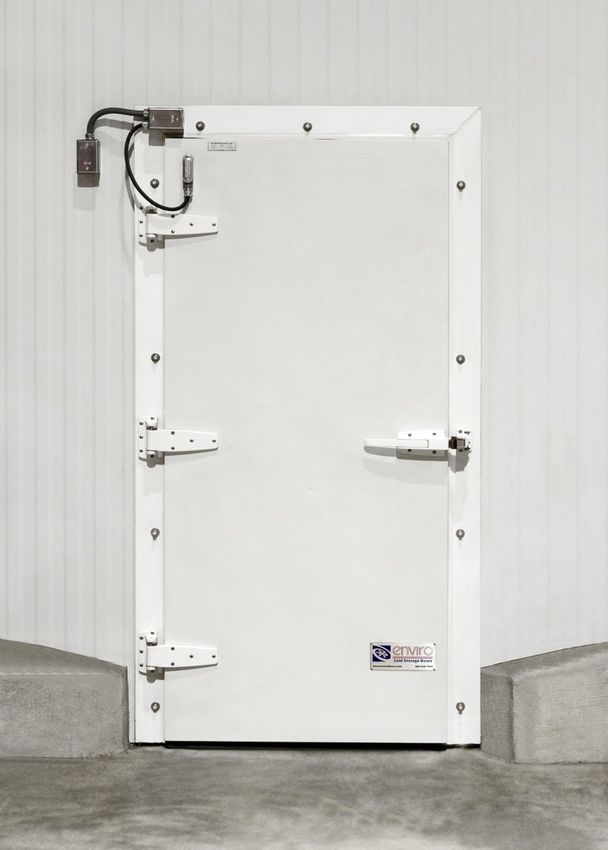
ASI Door ID Label
Door Identification
Determining the Job Number, Model, and Year
of Manufacture of your door is necessary to
provide quick and accurate parts identifica-
tion. Each door has an ID label showing this
information. Refer to Figures # 10 & 11 for the
ID label and it’s location.
Figure 10: ID Label Location.
ASI DOORS, INC.
DOOR MODEL JOB NUMBER DOOR NUMBER
MFG. DATE INSPECTED BY WIRING DIAG. #
(800) 558-7068 MILWAUKEE, WI. USA
Figure 11: Infit Door ID Label.
Manual Part Number: 17A274-191216 © 2020 ASI Doors, Inc. Page 13
1-800-558-7068Replacement Parts
Infit Doors Door & Frame Parts
DESCRIPTION PART # ITEM #
FRAME OPTIONS, FLUSH FLOOR, COOLER/FREEZER, SINGLE INFIT 55B0229 1
FRAME OPTIONS, HIGH SILL, COOLER/FREEZER, SINGLE INFIT 55B0230 1
INSIDE TRIM OPTIONS, INFIT DOOR 55B0231 2
PANEL OPTIONS, SINGLE INFIT 55B0232 3
HINGE OPTIONS, INFIT DOOR 55B0236 4
LATCH/STRIKE OPTIONS, INFIT DOOR 55B0237 5
CLOSER OPTIONS, INFIT DOOR (SEE NOTE #3) 55B0238 6
JAMB OPTIONS, EMPTY, INFIT DOOR 55B0239 7
JAMB OPTIONS, FILLED, INFIT DOOR 55B0240 7
EXIT DEVICE OPTIONS, INFIT DOOR (SEE NOTE #3) 55B0067 8
RAIN HOOD OPTIONS, INFIT DOOR (SEE NOTE #3) 55B0243 9
ASI BUMP BAR OPTION 55C779 10
ELECTRICAL BOX, WEATHERPROOF, SNGL-GANG (FREEZERS ONLY) 22B029 11
BELL BOX COVER & GASKET (FREEZERS ONLY) 22A084 11
HEATER WIRE, VARIABLE RESISTANCE (SEE NOTE #4) (FREEZERS ONLY) 22A069 12
UNILET CONNECTOR BOX (FREEZERS ONLY) 13B093 13
COVER, UNILET BOX (FREEZERS ONLY) 22A136-2 13
GASKET, UNILET BOX (FREEZERS ONLY) 22A136-3 13
STRAIN RELIEF, .438-.500 DIA. (FREEZERS ONLY) 23A031 14
CABLE, 14 GA./3 COND., 600V (FREEZERS ONLY) 22A044-1 15
COVER, HEATER FRAME, INFIT, TOP/BOTTOM (FREEZERS ONLY) 13B2026NV 16
COVER, HEATER FRAME, INFIT, RH, FLUSH FLOOR (FREEZERS ONLY) 13B2027RV 17
COVER, HEATER FRAME, INFIT, RH/LH, HIGH SILL (FREEZERS ONLY) 13B2028NV 17
COVER, HEATER FRAME, INFIT, LH, FLUSH FLOOR (FREEZERS ONLY) 13B2027LV 18
COVER, HEATER FRAME, INFIT, RH/LH, HIGH SILL (FREEZERS ONLY) 13B2028NV 18
SHIM, HINGE, 9” 11A156 19
SHIM, HINGE, 17” 16B041 19
SHIM, K-56 STRIKE, 1/8” 11B028 20
ASSEMBLY, HEAT TAPE, INFIT (FREEZERS ONLY) 24C0088NV 21
HEAT TAPE COVER, SWEEP, INFIT (FREEZERS ONLY) 13B2057NV 22
GASKET, SWEEP, 3", WIC + 2.5" (FREEZERS ONLY) 15A017 23
BRACKET, SWEEP GASKET, 1", INFIT (FREEZERS ONLY) 13B2056NV 24
DOOR GASKET, “P” PROFILE, (2 * HIC) + (WIC) + 1.0” 15A070 25
Notes:
1. Door shown in Figure #12 is a Flush Floor Right Hand model, and is for reference only.
2. References to part numbers beginning with “55” represent multiple options, and actual re-
placement P/N will be different depending on your specific installation. Consult ASI Service
department to verify correct P/N needed.
3. Most optional components are shown or listed on the following pages.
4. Resistance of heater wire is determined by door type, HIC , and WIC. Consult ASI Service
department to verify correct P/N needed.
Page 14 © 2020 ASI Doors, Inc. Manual Part Number: 17A274-191216
1-800-558-7068Replacement Parts
Door & Frame Parts Continued Infit Doors
7
2
11 14
15
16
17
13
14
15
19
4
20
5
19
4
5
1 12
18 25 22
3 24
When ordering parts, specify Job Number, 21
Door Number, and Manufacture Date.
23
Figure 12: Single Infit Door Parts view.
Manual Part Number: 17A274-191216 © 2020 ASI Doors, Inc. Page 15
1-800-558-7068Replacement Parts
Infit Doors Hinge Options
F08 F07 F06 F05 F04 F03 F02 F01 DESCRIPTION PART #
X HINGE OPTION, 9", POLISHED ALUMINUM 55B0236F01
X HINGE OPTION, 9", WHITE POWDER COAT 55B0236F02
X HINGE OPTION, 9", GREY POWDER COAT 55B0236F03
X HINGE OPTION, 9", STAINLESS 55B0236F04
X HINGE OPTION, 17", WHITE POWDER COAT 55B0236F05
X HINGE OPTION, 17", GREY POWDER COAT 55B0236F06
X HINGE OPTION, 17" STAINLESS 55B0236F07
X HINGE OPTION, 17" CHROME 55B0236F08
- - - - - - - AR HINGE, 9" ALUM, CAM, 1-3/8" OFFSET 16A150NN60
- - - - - - AR - HINGE, 9" WHT, CAM, 1-3/8" OFFSET 16A150NN70
- - - - - AR - - HINGE, 9" GRY, CAM, 1-3/8" OFFSET 16A150NN75
- - - - AR - - - HINGE, 9" S/S, CAM, 1-3/8" OFFSET 16A150NN20
- - - AR - - - - HINGE, 17" WHT, CAM, 1-5/8" OFFSET 16A073
- - AR - - - - - HINGE, 17" GRY, CAM, 1-5/8" OFFSET 16A088
- AR - - - - - - HINGE, 17" S/S, CAM, 1-5/8" OFFSET 16A151NN20
AR - - - - - - - HINGE, 17" CHR, CAM, 1-5/8" OFFSET 16A778
- - - - AR AR AR AR SHIM, HINGE BUTT, 9" HINGE (1 PER HINGE) 11A156
AR AR AR AR - - - - SHIM, HINGE BUTT, 17" HINGE (1 PER HINGE) 16B041
When ordering parts, specify Job Number,
Door Number, and Manufacture Date.
Latch & Strike Options
F06 F05 F04 F03 F02 F01 DESCRIPTION PART #
- - - - - X LATCH/STRIKE, INFIT, POLISHED CHROME 55B0237F01
- - - - X - LATCH/STRIKE, INFIT, WHITE PC 55B0237F02
- - - X - - LATCH/STRIKE, INFIT, GRAY PC 55B0237F03
- - X - - - LATCH/STRIKE, INFIT, STAINLESS (FROM CHG) 55B0237F04
- X - - - - LATCH/STRIKE, INFIT, CYLINDER LOCK, POLISHED CHROME 55B0237F05
X - - - - - LATCH/STRIKE, INFIT, HD W/ PUSH PADDLE, CHROME 55B0237F06
- 1 - - - 1 STRIKE, 1-1/8" OFFSET, CHROME 16A030
- - - - 1 - STRIKE, NYLON WHITE, 3/4" TO 1-1/2" OFFSET 16A065
- - - 1 - - STRIKE, BAY FOG GRAY, 3/4" TO 1-1/2" OFFSET 16A091
- - 1 - - - STRIKE, STAINLESS 16A097
- - - - - 1 LATCH, CHROME 16A033
- - - - 1 - LATCH, NYLON WHITE 16A064
- - - 1 - - LATCH, BAY FOG GRAY 16A090
- - 1 - - - LATCH, STAINLESS 16A096
- 1 - - - - LATCH, CYLINDER LOCK, POLISHED CHROME 16A035
1 - - - - - LATCH ASM, HD, 1-1/8" OFFSET 16A038F1
- - - - - - LATCH ASM, HD, FLUSH MOUNT 16A038F2
AR AR AR AR AR AR INSIDE RELEASE, 4” DOOR 16A045F1
AR AR AR AR AR AR INSIDE RELEASE, 6” DOOR 16A045F2
- 1 1 1 1 1 SHIM, STRIKE 11B028
Page 16 © 2020 ASI Doors, Inc. Manual Part Number: 17A274-191216
1-800-558-7068Replacement Parts
Emergency Exit Bar Infit Doors
QTY DESCRIPTION PART # ITEM #
ASM, EMERGENCY EXIT DEVICE, INFIT 55C779 -
1 INFIT DOOR ASM A/R 1
1 EMERGENCY EXIT BUMP BAR 16B0048NN20 2
6 SCREW, 1/4-20 X 1.50 PH OHMS SS 41A160 3
A/R LOCKTITE, #242, THREADLOCK 10A010 4
Emg Exit Bar with STD Release Emg Exit Bar with Paddle Release
3 4 3 4
2
Figure 14: Optional Emergency Exit Devices.
Notes:
1. Normally used with standard Latches & Strikes. Shown with STD & Paddle inside releases.
When ordering parts, specify Job Number,
Door Number, and Manufacture Date.
Manual Part Number: 17A274-191216 © 2020 ASI Doors, Inc. Page 17
1-800-558-7068Replacement Parts
Infit Doors Optional Handles & Exit Only Bar
F10 F09 F08 F07 F06 F05 F04 F03 F02 F01 DESCRIPTION PART # ITEM #
- - - - - - - - - X EXIT ONLY, DORMA, ALUMINUM 55B0067F01 -
- - - - - - - - X - EXIT ONLY, DORMA, STAINLESS 55B0067F02 -
- - - - - - - X - - ALUMINUM, EXT KNOB, NO KEY 55B0067F03 -
- - - - - - X - - - ALUMINUM, EXT KNOB, WITH KEY 55B0067F04 -
- - - - - X - - - - ALUMINUM, EXT LEVER, NO KEY 55B0067F05 -
- - - - X - - - - - ALUMINUM, EXT LEVER, WITH KEY 55B0067F06 -
- - - X - - - - - - STAINLESS, EXT KNOB, NO KEY 55B0067F07 -
- - X - - - - - - - STAINLESS, EXT KNOB, WITH KEY 55B0067F08 -
- X - - - - - - - - STAINLESS, EXT LEVER, NO KEY 55B0067F09 -
X - - - - - - - - - STAINLESS, EXT LEVER, WITH KEY 55B0067F10 -
- - - - 1 1 1 1 - 1 BAR, EXIT ONLY, ALUMINUM 16A107 1
1 1 1 1 - - - - 1 - BAR, EXIT ONLY, STAINLESS 16A120 1
- - - 1 - - - 1 - - ROUND KNOB, NO LOCK ALUM. FINISH 16A0161NN60 2
- - 1 - - - 1 - - - ROUND KNOB, WITH LOCK ALUM. FINISH 16A0162NN60 3
- 1 - - - 1 - - - - DOOR LEVER, NO LOCK ALUM. FINISH 16A0163NN60 4
1 - - - 1 - - - - - DOOR LEVER, WITH LOCK ALUM. FINISH 16A0164NN60 5
2 2 2 2 2 2 2 2 - - SCREW, #10-32 X 4.50" ROUND HEAD PHILLIPS, ZN 41A226 6
1 - 1 - 1 - 1 - - - KEYWAY, BEST P/N IC7-A-26D 16A0165 7
1 1 1 1 1 1 1 1 - - WELDMENT, DORMA EXTENSION 16A0156 8
A/R A/R A/R A/R A/R A/R A/R A/R A/R A/R SHIM, STRIKE, DORMA, 4-1/2" X 1-5/8" 11A169 9
6 6 6 6 6 6 6 6 3 3 SCREW, 1/4-20 X 1.50, PH, FHMS, S/S 41A160 10
A/R A/R A/R A/R A/R A/R A/R A/R A/R A/R LOCKTITE, #242, THREADLOCK 10A010 11
Page 18 © 2020 ASI Doors, Inc. Manual Part Number: 17A274-191216
1-800-558-7068Replacement Parts
Optional Handles & Exit Only Bar Continued Infit Doors
2 3 4 5
1
Optional Round Door Knob Optional Door Lever Optional Exit Only Bar
Figure 15: Optional handles and Exit only Device.
Notes:
1. Exit Only Bar shown is Normally used in “Exit Only” applications,
and typically replaces standard Latches & Strikes.
When ordering parts, specify Job Number,
Door Number, and Manufacture Date.
Manual Part Number: 17A274-191216 © 2020 ASI Doors, Inc. Page 19
1-800-558-7068Replacement Parts
Infit Doors Rain Hood
F3 F2 F1 DESCRIPTION PART # ITEM #
- - 1 ASSEMBLY, RAIN HOOD, GALV 55B0243F01 1
- 1 - ASSEMBLY, RAIN HOOD, S/S 55B0243F02 1
1 - - ASSEMBLY, RAIN HOOD, WHT MTL 55B0243F03 1
Note:
1. Installer to provide 1/4” hardware appropriate
for wall surface at install site to attach Hood.
Figure 16: Optional Rain Hood.
When ordering parts, specify Job Number,
Door Number, and Manufacture Date.
Page 20 © 2020 ASI Doors, Inc. Manual Part Number: 17A274-191216
1-800-558-7068asidoors.com ASI Doors, Inc. 5848 North 95th Court, Milwaukee, WI 53225 (800) 558-7068
You can also read