Owner's Manual Supplement - WARNING - Cannondale
←
→
Page content transcription
If your browser does not render page correctly, please read the page content below
Owner’s Manual Supplement

       WARNING
 READ THIS SUPPLEMENT AND YOUR
 CANNONDALE BICYCLE OWNER’S MANUAL.
 Both contain important safety information. Keep
 both for future reference.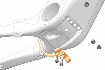
Topstone - Owner’s Manual Supplement

                                            Safety Messages
                             In this supplement, particularly important information
                                        is presented in the following ways:

                                  Indicates a hazardous situation which, if
                                  not avoided, may result in death or serious
                                  injury.

                                  NOTICE
                                  Indicates special precautions that must be
                                  taken to avoid damage.

                                 The following symbols are used in this manual:

     Symbol         Name                                  Description
       NG
           LI
              -2    NGLI-2 synthetic grease               Apply NGLI-2 synthetic grease.

      CR
        B-
             GE
                L   Carbon gel                            Apply carbon gel (friction paste) KF115/

                    Medium-strength
       2                                                  Apply Loctite® 242 (blue) or equivalent.
                    removable thread lock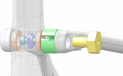
English

 Cannondale Supplements                                CONTENTS
 This manual is a “supplement” to your
 Cannondale Bicycle Owner’s Manual.                    Safety Information.....................2-5
 This supplement provides additional and               Technical Information..............6-19
 important model specific safety, maintenance,
 and technical information. It may be one of           Replacement Parts...................... 20
 several important manuals/supplements for
 your bike; obtain and read all of them.
 Please contact your Authorized Cannondale
 Dealer immediately if you need a manual
 or supplement, or have a question about
 your bike. You may also contact us using
 the appropriate country/region/location               Your Cannondale Dealer
 information.
                                                       To make sure your bike is serviced and
 You can download Adobe Acrobat PDF                    maintained correctly, and that you protect
 versions of any manual/supplement from our            applicable warranties, please coordinate
 website: www.cannondale.com                           all service and maintenance through your
                                                       Authorized Cannondale Dealer.

                                                        NOTICE
 Contacting Cannondale                                  Unauthorized service, maintenance, or
                                                        repair parts can result in serious damage
 Cannondale USA                                         and void your warranty.
 Cycling Sports Group, Inc.
 1 Cannondale Way, Wilton CT, 06897, USA
 1-800-726-BIKE (2453)

 Cycling Sports Group Europe B.V
 Mail: Postbus 5100
 Visits: Hanzepoort 27
 7575 DB, Oldenzaal, Netherlands

 International Distributors
 Consult our websIte to identify the appropriate
 Cannondale Dealer for your region.

134949                                             1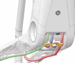
Topstone - Owner’s Manual Supplement

                             SAFETY INFORMATION

 Important Composites                               Inspection & Crash Damage
 Message                                            Of Carbon Frames/Forks

  Your bike (frame and components) is made          After A Crash Or Impact:
  from composite materials also known as
  “carbon fiber.”                                   Inspect frame carefully for damage. See
                                                    PART II, Section D. Inspect For Safety in
  All riders must understand a fundamental          your Cannondale Bicycle Owner’s Manual.
  reality of composites. Composite materials
  constructed of carbon fibers are strong           Do not ride your bike if you see any sign
  and light, but when crashed or overloaded,        of damage, such as broken, splintered, or
  carbon fibers do not bend, they break.            delaminated carbon fiber.

  For your safety, as you own and use the           Any of the following may indicate a
  bike, you must follow proper service,             delamination or damage:
  maintenance, and inspection of all the            •    An unusual or strange feel to the
  composites (frame, stem, fork, handlebar,              frame
  seat post, etc.) Ask your Cannondale
  Dealer for help.                                  •    Carbon which has a soft feel or
                                                         altered shape
  We urge you to read PART II, Section D.
  “Inspect For Safety” in your Cannondale           •    ·Creaking or other unexplained noises,
  Bicycle Owner’s Manual BEFORE you ride.
                                                    •    Visible cracks, a white or milky color
  You can be severely injured, paralyzed                 present in carbon fiber section
  or killed in an accident if you ignore this
                                                    Continuing to ride a damaged frame
  warning.
                                                    increases the chances of frame failure,
                                                    with the possibility of injury or death of
                                                    the rider.

134949                                          2
English
Intended Use Disc Brakes on Road Bikes
ASTM F2043
The intended use of all
models is
ASTM CONDITION 2,
General Purpose Riding. Relative to conventional rim brakes, disc
For off-road
riding and brakes are less affected by water, do not
jumps less than
12” (30cm)
wear or heat the rims and therefore are
more consistent. Disc brakes also may be
more powerful.
To minimize risk of injury or accidents:
Please read your Cannondale Bicycle • Understand that road bikes have a
Owner’s Manual for more information about relatively small tire contact patch (part
Intended Use and Conditions 1-5. of the tire that touches the road). In
order to apply the brakes safely and
effectively, you may need more or less
braking force in different situations.
You need to take into account various
road and weather conditions that can
Servicing affect traction.
• Disc brakes are excellent, but not
some kind of magic. Take some time
riding your new disc brake road bike in
This supplement may include procedures lower risk circumstances to get used
beyond the scope of general mechanical to the feel and performance of the
aptitude. disc brakes and tires.
Special tools, skills, and knowledge may You can be severely injured, paralyzed
be required. Improper mechanical work or killed in an accident if you ignore this
increases the risk of an accident. Any message.
bicycle accident has risk of serious injury,
paralysis or death.
To minimize risk we strongly recommend
that owners always have mechanical
work done by an Authorized Cannondale
Dealer.
134949 3Topstone - Owner’s Manual Supplement
Trainers Water Bottles
If you ride a trainer that requires removal of the Side impacts to a water bottle or cage can
front wheel and clamps the fork dropouts: Be result in damage to threaded inserts due to
sure your fork quick release is tight! Relative the leverage on a very small area. In a crash,
movement will wear parts, weaken and certainly the last thing you should be worried
damage your bike. about is saving the threaded inserts in your
frame. However, when you are storing or
If you ride a trainer that holds the bike up by
transporting your bike, take steps to prevent
clamping the rear quick release between two
situations where a water bottle may be hit or
cones: Take off the lightweight quick release
bumped by a strong force that would cause
that came with your bike. Substitute a heavy,
damage. Remove bottle and cage when you
classic all steel quick release and clamp it
are packing your bike for travel.
tight! Relative movement will wear parts,
weaken and damage your bike. Note that Periodically check the attachment of the bottle
many modern quick releases will not fit the cage; tighten the cage bolts if necessary.
clamping cones in this kind of trainer because Don’t ride with a loose bottle cage. Riding
their shapes are incompatible. with loose cage bolts can produce a rocking
motion or vibration of the attached cage. A
For thru axles, make sure you follow the
loose cage will damage the insert and possibly
trainer manufacturer instructions for the use
lead to the inserts to pull out.
of any required adapters.
It may be possible to repair a loose insert,
Be particularly cautious with a carbon frame or install another insert only if the frame is
or fork. Carbon is relatively soft, not abrasion undamaged. Replacement requires the use
resistant. If there is any relative movement, of a special tool. If you notice damage to the
carbon will wear quickly. threaded insert, please ask your Cannondale
Dealer for help.
If you ride a trainer a lot, consider using an
old bike: Corrosion from sweat will take its
toll. Weight is irrelevant. Save wear on your
expensive components.
Ask you dealer for help with trainers, the right
one and the correct way to use it.
NOTICE
TRAINERS - Improperly mounting a
bike in a trainer, or using one that is not
compatible with your particular bike frame
can cause serious damage.
WATER BOTTLES - An impact, crash, or
loose bottle cage can result in damage to
your frame.
This kind of damage is not covered by the
Cannondale Limited Warranty.
134949 4English
Building Up A Frame Set Tightening Torques
Before building up a frame set, consult with Correct tightening torque for the fasteners
your Cannondale Dealer and the component (bolts, screws, nuts) on your bicycle is very
manufacturers, and discuss your riding style, important to your safety. Correct tightening
ability, weight, and interest in and patience for torque for the fasteners is also important for
maintenance. the durability and performance of your bicycle.
We urge you to have your dealer correctly
Make sure the components chosen are
torque all fasteners using a torque wrench. If
compatible with your bike and intended for
you decide to torque fasteners yourself always
your weight and riding style.
use a torque wrench.
Generally speaking, lighter weight
Find Tightening Torque Information :
components have shorter lives. In selecting
lightweight components, you are making a
trade-off, favoring the higher performance The wide range of bicycle models and
that comes with less weight over longevity. components used means that a listing of
If you choose more lightweight components, tightening torque would be out of date by
you must inspect them more frequently. If you the time it was published. Many fasteners
are a heavier rider or have a rough, abusive should be installed with a thread locking
or “go for it” riding style, buy heavy duty adhesive such as Loctite®.
components.
To determine correct tightening torque
Read and follow the component and any adhesive application for a
manufacturers warnings and instructions. fastener we ask you to check:
• Many components are marked.
On-product marking is becoming
common.
• ·Torque specs in the component
manufacturers instructions shipped
with your bicycle.
• Torque specs listed on the websites of
component manufacturers.
• With your dealer. Dealers have access
to current data and have experience
with correct torque for most
fasteners.
134949 5Topstone - Owner’s Manual Supplement
TECHNICAL INFORMATION
Frame Specification
Item Specification
Head Tube UPR: 1-1/8 in, LWR: 1-1/2 in
Headset Integrated, 1-1/8 in - 1-1/2 in
Bottom Bracket: Type / Width BB30A / 83 mm
Front Derailleur Brazed-on
Seat Post: Dia./Binder 27.2 mm / Internal Wedge
Min. Seat Post Insert 65 mm
Max. Seat Post Insert XS: 140 mm, S-XL: 188 mm , See page 13.
Tire Size x Max. Width 700c x 40 mm (measured), 650b x 48 mm (measured)
RR: Flat Mount / 140 mm / 160 mm
Brakes: Mount Type/Min/Max Rotor Dia.
FT: Flat Mount +20mm / 160 mm / 180 mm
RR: Speed Release, Double Lead / 142 x 12 mm,
165 mm Length
Axles: Type/Length
FT: Speed Release, Double Lead / 100 x 12 mm,
119 mm Length
Ai Offset Rear Wheel: 6mm Offset to NDS
Intended Use: ASTM Condition 2
Max. Weight Limit: Total 305 lbs / 138 kg
134949 6English
Geometry
B
A Seat Tube Length P
B Top Tube Horizontal
D Head Tube Angle A C
G
E Seat Tube Angle
(effective) 75 mm
F Standover F
G Head Tube Length O
H Wheelbase D
I Front Center E
J Chain Stay Length K
K Bottom Bracket Drop
I M
L Bottom Bracket Height J
M Fork Rake L
N Trail
O Stack
N
P Reach H
Dimensions = centimeter/inches
Size XS S M L XL
A 41.0/16.1 45.8/18.0 50.5/19.9 55.3/21.8 60.0/23.6
B 52.5/20.7 54.4/21.4 56.1/22.1 57.9/22.8 59.6/23.5
D 70.0° 71.2° * * *
E 73.1° * * * *
F 71.5/28.1 76.1/30.0 80.3/31.6 84.3/33.2 88.5/34.8
G 9.7/3.8 13.1/5.2 16.5/6.5 19.8/7.8 23.2/9.1
H 99.9/39.3 101.0/39.8 103.0/40.6 104.9/41.3 106.8/42.1
I 59.4/23.4 60.4/23.8 62.3/24.5 64.2/25.3 66.0/26.0
J 41.5/16.3 * * * *
K 6.9/2.7 6.4/2.5 6.1/2.4 * 5.9/2.3
L 27.3/10.7 27.8/10.9 28.1/11.1 * 28.3/11.1
M 5.5/2.2 * * * *
N 6.6/2.6 5.8/2.3 * * *
O 51.8/20.4 55.0/21.6 57.9/22.8 61.0/24.0 64.1/25.2
P 36.8/14.5 37.7/14.8 38.5/15.2 39.4/15.5 40.1/15.8
* Indicates same. All Specifications subject to change without notice.
134949 7Topstone - Owner’s Manual Supplement
Rear Derailleur Mount Front Derailleur Mount
2
LI- a
NG
b
2
2
2 N·m 1
1
2 3
1. RD Mount 1. FD Mount a. Di2 Frame exit
2. Screw 2. Screws (2X) b. Di2 Mount exit
3. Cover
To replace:
Remove the rear axle. Serial Number
Remove the mounting screw(s) and remove
the old hanger from the dropout. Clean the
area around the dropout and inspect the
frame carefully for any cracks or damage. If
you find damage have the frame inspected by 1
your Cannondale Dealer .
If the dropout is un-damaged, apply a light
film of grease between the frame and mount.
This will help minimize any noise or “creaking”
that might result from very slight movement
between the dropout and hanger during
movement of the derailleur.
Slide the new hanger onto the dropout. Apply
Loctite® 242 (or medium strength thread
lock) to the screw threads and tighten to the
specified torque.
The serial number is located on the bottom
bracket. It is a 7-character barcode (1). Use
this serial number to register your bike.
To register your bike: go to the
Product Registration section of our
website at www.cannondale.com
134949 8English
Bottom Bracket Cable Guide
Di2
3
4
a Identification
1. BB Guide
2. Screw (2X)
2 1 3. Di2 Cable Plug
4. Plug
a. Drain hole
Rear Fender Support
Identification Maintain tire clearance with fender.
1. Fender Support
2. Screw (2X)
45mm
1
NGL
I-2
2 N·m The wheel rim and tire models, and
M5 fender shape used will affect the fender
2 clearance.
M5 x 1.0 x 12 mm
Please Note: (1) Check tire clearance with the tire fully inflated. (2) Mounting a tire with a smaller profile, one
smaller than the maximum tire size for the frame, or currently on the wheel may be required to fit a compatible
fender. (3) Any fender must be secured by the support and should not be loose. (4) Do not modify any parts or the
frame in order to install a fender.
134949 9Topstone - Owner’s Manual Supplement
Bottom Bracket - BB30A / 83 mm
NG
LI-2
a c
b 2 83 mm
1 QC616/ 39 mm 44 mm
KB6180/
Identification 3
1. Bearing (2X) KT011/
2. Circlip (2X)
3. Tool, Bearing Removal
a. Hook end
b. Gap
c. Groove
Maintenance Replacement
In general, you should inspect the condition of the
bearings annually (at a minimum) or anytime the NOTICE
crankset assembly is disassembled, serviced, or if a
problem is indicated. Consult with your Cannondale Dealer on the quality
and compatibilty of any proposed replacement
To inspect, when the crankset is removed, rotate the component.
inner bearing race of both bearings; rotation should
be smooth and quiet. Execessive play, roughness, or Do not use chemical solvents to clean. Do not
remove frame material or use surfacing tools on
corrosion indicates a damaged bearing.
bottom bracket shell.
Frame damage, caused by improper components,
Removal component installation or removal is not covered by
To avoid serious damage to the frame, it is important the limited warranty.
to remove bearing systems very carefully using
proper tools indicated by the manufacturer’s service
instructions. Make sure the bearings (cup or adapter
parts) are driven out squarely and evenly from inside
the shell! Do not pry components from shell.
134949 10English
Routing
RB
RD FD
SP
Identification
FD - Front Derailleur
RD - Rear Derailleur
RB - Rear Brake
SP - Seat post Battery
Di2 - Plug
SP
RB
RD
FD
SP
RD
Di2
FD
RB
Di2
134949 11Topstone - Owner’s Manual Supplement
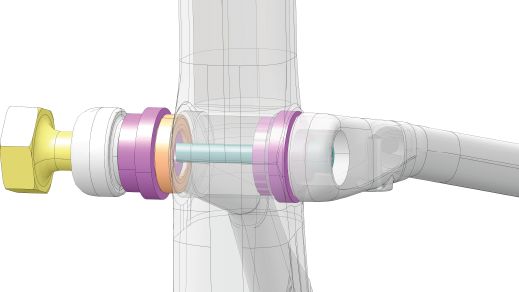
LockR
To remove the LockR from the frame:
1. Loosen the screw 4-6 turns using a T25 Torx key.
2. Tap head of screw with a rubber mallet to un-seat the wedge bolt located on the opposite side.
3. Remove the screw and wedge bolt from the still-installed axle.
4. If the wedge did not come out with the screw, insert a 5 mm hex key and turn to free and remove
it. If wedge still sticks insert a wooden or plastic dowel into the drive side and drive it out.
5. To remove the axle itself, insert a 6 mm hex key into the axle on the non-drive side and turn
counter-clockwise until it can be removed.
To install the LockR on the frame:
1. Disassemble and clean all parts of the LockR axle. Do not install it assembled.
Inspect the parts for damage (burrs, scratches, deformity, wear). Replace the entire LockR
assembly if any damage is found.
2. Apply a light coating of a high-quality bicycle bearing grease to all parts.
3. Align the linkage and bearing and insert the threaded end of the pivot axle (1) in from the
non-drive side.
4. Tighten the inserted pivot axle to 1 Nm using a 6 mm hex key fitted torque wrench from the
non-drive side.
5. Insert the wedge bolt (2) into the drive side of the axle and insert the small end of the wedge (3)
into the non-drive side axle head.
6. Thread the screw (4) into wedge bolt with a wrench and tighten to 5.0 Nm.
NOTICE
Use a calibrated torque wrench. Exceeding 1
N·m will result in permanent damage to the
LockR pivot system.
134949 12English
• Do not install assembled.
• Apply grease to all parts.
2
1 N·m
1
NGLI-2
3
5 N·m
4
-2
LI
NG
Unthread & dislodge & Insert 5mm & Unthread
tap mallet remove turn to free Remove Remove
3
1
m m
5m
3
6m
T25 4
134949 13Topstone - Owner’s Manual Supplement
Seat Tube / Seat Stay Pivot Bearings
5. Pull SS end away from ST just enough to allow
REMOVE
remove cup (5) to be snapped over M6X30mm
screw (7).
1. Remove LockR pivot hardware.
6. Hold M6X30mm screw (7) stationary with 5mm
2. Insert remove plate (4) through ST pivot so it’s hex key while turning tool handle (3) until bearing
small OD cylindrical surface engages the inside of is fully pulled out of pivot and into remove cup.
the bearing.
7. Unthread tool handle to remove tool from the
3. Insert M5X30mm screw (7) through hole in remo- frame.
ve plate (4) so threads are pointing out through SS
pivot end. 8. Repeat for the other side.
4. Thread tool handle (3) onto M6X30mm screw (7)
only 2-3 turns.
7. Remove Tool handle (3), M6X70 screw (6) and
INSTALL
drive side install plate (2).
1. Pull drive side SS end away from ST just enough to 8. Place new bearing on smaller OD side of install
slip larger OD side of install plate (2) into ST pivot plate (2).
bore.
9. Apply grease to drive side ST pivot bore
2. Place new bearing on smaller OD side of 2nd install
10. Pull drive side SS end away from ST just enough to
plate (2).
slip install plate (2) and bearing into position.
3. Apply grease to non-drive side ST pivot bore.
11. Insert M6X70mm screw (6) through both install
4. Pull non-drive side SS end away from ST just plates so it’s threaded end protrudes through SS
enough to slip 2nd install plate (2) and bearing into end on drive side.
position.
12. Thread tool handle (3) onto M6X70mm screw (6)
5. Insert M6X70mm screw (6) through both install and tighten while holding screw stationary with
plates so it’s threaded end protrudes through SS 5mm hex key. Tighten until bearing is fully pressed
end on non-drive side. into ST pivot bore.
6. Thread tool handle (3) onto M6X70mm screw (6) 13. Unthread tool handle (3) and remove all tools from
and tighten while holding screw stationary with pivot.
5mm hex key. Tighten until bearing is fully pressed
14. Continue with LockR axle installation procedure.
into ST pivot bore.
134949 14English
REMOVE
1
ST 5
4
3
SS
7
M6 x 30 mm
REMOVE
1
3 2 2
SS ST
SS
6
M6 x 70 mm
NGLI-2
Identification
1. Bearing 5. Remove Cup SS Seat Stay (end)
2. Install Plate 6. Screw M6 x 70mm
3. Tool Handle 7. Screw M6 x 30 mm
4. Remove Plate ST Seat Tube
134949 15Topstone - Owner’s Manual Supplement
Seat Binder
CRB-GEL
EL
B- G
CR
5
1 2 2
4
3 Identification
1. Wedge
2. Retaining Screw
3. Binder Screw
4. Wedge
5. Frame Pocket
2
LI-
NG
Periodically, to maintain the seat binder assembly, it is recommended to:
1. Remove the seat post. 5. Apply grease to the binder screw (3) and thread
2-3 turns into the wedge (4).
2. Use a 4mm hex key and your finger to the binder
assembly from the frame pocket (5). 6. Clean the frame pocket and the inside of the seat
tube. Use acetone or isopropyl alcohol. Wipe with
3. Disassemble the binder parts. Clean the binder a dry shop towel. Insert the binder assembly into
parts to remove any old grease and carbon gel/ the frame pocket.
friction paste. Use only acetone or isopropyl
alcohol and a clean shop towel. 7. Use a 4mm hex key and your finger and return the
assembly into the frame pocket.
4. Apply light grease only to the wedge (1) surface
shown above. Don’t grease the wedge surface 8. Install the seat post.
that faces the seat post. Reassemble the wed-
ges. Apply Loctite® 242 to the retaining screw (2)
threads. Tighten the retaining screw lightly, then
back it off one half of a turn so that the wedge
parts slide freely.
Wear safety glasses and hand protection when
performing any work.Acetone and isopropyl alcohol
are flammable liquids. Handle carefully. Wipe up
chemical spills immediately.
134949 16English
Seat Post
Removal
To remove the seat post, insert a 4mm hex
key into the frame opening under the seat
1 tube top tube junction. Turn the wedge bolt
counter-clockwise to loosen it. When bolt is
loose simply lift the seat post up out of the
Min. seat tube. Then use the hex key and your
65mm finger to guide the seat binder of the frame
socket.
2
Installation
Max.
Before inserting the seat post into the frame,
5mm a use a clean shop towel to wipe out any
residual carbon gel paste from the inside the
seat tube. Do not use any spray cleaners or
solvents.
Apply fresh carbon friction gel to the seat post
and place a little bit inside the seat tube.See
1. Seat Post a. Bottom Out limit also “Seat Binder.”
2. Seat Binder
Clean the wedge assembly and lightly grease
the parts. Apply Loctite (242 (blue) to the
small assembly screw, assemble, tighten
Minimum Insert finger tight and back off 1/2 turn so the
wedge parts move freely. Insert the loosened
The minimum insert depth the seat post must
assembly into the frame, then carefully insert
be inserted into the frame is 65mm.
the seat post into the frame.
Maximum Insert Set the saddle height, and tighten the clamp
bolt to the specified torque with a torque
The total length of seat post that may be wrench.
inserted will vary with the frame size and
should be checked in each frame.
Maintenance
Frame Size Maximum Insert Periodically, remove the seat post and the
(cm) (mm) clamp assembly to clean, inspect for damage
XS 140 and renew the application of grease and/or
carbon gel.
S - XL 188
NOTICE For more information about carbon
Use the correct seat post length shown fiber seat posts, see also “Care and
above. Do not force or bottom-out the seat Maintenance of Carbon Fiber Seat Posts”
post inside the frame. in your Cannondale Bicycle Owner’s
Manual.
134949 17Topstone - Owner’s Manual Supplement Sizing a seat post If the seat post must be cut, use the appropriate saw blade for the seat post material, aluminum or carbon. Lightly sand the edges of the cut seat tube with light sandpaper. Re-mark the minimum insert line on the post. Be sure to remove any installed battery before cutting a seat post. The seat post must only be cut by a professional bike mechanic. Incorrectly cutting the seat post can result in damage leading to an accident. 134949 18
English

 Water Bottle / Fender Mount Fasteners

    NGL
         I-2
                                                                                      M5 x 1.0 x 25 mm
    2 N·m
     M5

                         M5 x 1.0 x 12 mm

                                                          M5 x 1.0 x 16 mm

          M5 x 1.0 x 16 mm
                                                                              M5 x 1.0 x 25 mm

                                                                   M5 x 1.0 x 25 mm

               NOTICE
               •    Do not use longer screws than the maximum lengths indicated at each
                    location above.
               •    Clean screw threads and apply lightly grease to the threads before
                    installation into the frame.
                    Tighten to 2 N·m. Do not over-tighten the screws.
               •    See also “Water Bottles,” page 4.

134949                                           19
Topstone - Owner’s Manual Supplement
REPLACEMENT PARTS
C
K
J
E
A
D N
F
2
1 N·m
M3
I
H 2
4 N·m
M5
B
M L G
Part Part
ID Description ID Description
Number Number
Derailleur Hanger TA ST SS 070 K K35009 SL Compression Plug with Top Cap
A K33009
*Double Lead L QC616/ Circlips (QTY-2)
B K32020 BB Cable Guide E256240 M KB6180/ BB30 Bearings
C K26058 27.2 Internal Seat Binder N K35010 1-1/8-1.5 Int Hdset w/ 36 Deg CR 25/5 TC
D K91000 LockR Pivot Hardware 65mm Speed Rel TA 142x12
-- K83010
E K36087 Pivot Bearing 6802 (QTY 2) 2Lead P1.0 Bolt 165L
F K11000 Topstone Crb Rear Fender Mount Speed Rel TA 100x12
-- K83000
2Lead P1.0 Bolt 119L
G K32079 Blank Frame Plugs (QTY 3)
H K33000 Topstone Crb Front Derailleur Mount
I K33010 Topstone Crb Front Derailleur 1X Cover
J K91010 Kingpin Bearing Install Removal Tool
134949 20WWW.CANNONDALE.COM
© 2019 Cycling Sports Group English
Topstone Owner’s Manual Supplement
134949 Rev. 1
CANNONDALE USA CANNONDALE EUROPE CANNONDALE UK
Cycling Sports Group, Inc. Cycling Sports Group Europe, B.V. Cycling Sports Group
1 Cannondale Way, Hanzepoort 27, 7570 GC, Oldenzaal, Vantage Way, The Fulcrum,
Wilton CT, 06897, USA Netherlands +41 61 4879380 Poole, Dorset, BH12 4NU
1-800-726-BIKE (2453) servicedeskeurope@ +44 (0)1202732288
cyclingsportsgroup.com
www.cannondale.com sales@cyclingsportsgroup.
co.ukWWW.CANNONDALE.COM
WWW.CANNONDALE.COM
© 2019 Cycling Sports Group
Topstone Owner’s Manual Supplement
134949 Rev. 1
CANNONDALE USA CANNONDALE EUROPE CANNONDALE UK
Cycling Sports
Cycling SportsGroup,
Group,Inc.
Inc. Cycling Sports
Cycling SportsGroup
GroupEurope,
Europe,B.V.
B.V. Cycling Sports
Cycling SportsGroup
Group
1 Cannondale
CannondaleWay,
Way, Hanzepoort
Mail: Postbus27,
5100
7570 GC, Oldenzaal, Vantage Way,
Vantage Way,The
TheFulcrum,
Fulcrum,
Wilton CT,
Wilton CT,06897,
06897,USA
USA Netherlands
Visits: +41 61
Hanzeport 27 4879380 Poole, Dorset,
Poole, Dorset,BH12
BH124NU
4NU
1-800-726-BIKE(2453)
1-800-726-BIKE (2453) servicedeskeurope@
7575 DB, Oldenzaal Netherlands +44 (0)1202732288
(0)1202732288
cyclingsportsgroup.com
www.cannondale.com
www.cannondale.com sales@cyclingsportsgroup.
sales@cyclingsportsgroup.
co.uk
co.ukYou can also read