IMPLEMENTATION OF HEART-RATE AND PULSE OXIMETRY MONITORING DEVICE WITH WIRELESS TEMPERATURE SENSOR
←
→
Page content transcription
If your browser does not render page correctly, please read the page content below

International Journal of Academy of Engineering Research and Theory (IJAERT), ISSN: 2545-5931
                                                                       Kureve T. Douglas, Tingir T. James, Kyari H. Jennifer
    Open Access                                                                                  Vol. 1, Issue 1, Feb. 2021 , Pp 1-7

    IMPLEMENTATION OF HEART-RATE AND PULSE OXIMETRY MONITORING
             DEVICE WITH WIRELESS TEMPERATURE SENSOR

                         Kureve T. Douglas1, Tingir T. James2, Kyari H. Jennifer3
                         1, 2, 3,
                                    Electrical and Electronics Engineering Department, Faculty of Engineering,
                                       Federal University of Agriculture, Makurdi, Benue State, Nigeria

                       Email: 1 kurevedt@gmail.com           2
                                                                 jaytinter@gmail.com 3jennahkyari@gmail.com

Abstract: High heart-rate values (known as tachycardia) are usually indicators of declining health or symptoms of underlying
heart disease. Heart-rate is associated with hypoxia (low blood oxygen level) which on its own could lead to permanent brain
damage. This research develops a heart- rate and blood oxyhemoglobin monitoring device using the MAX30100 IC (for the heart-
rate and pulse oximeter reading), an Arduino UNO IC (ATMEGA328P) as the central controller, an MLX90614 infrared
temperature module and a piezo buzzer for alarm system. The measurement period was 30 seconds and a 16 by 2 LCD displayed
the heart-rate and blood oxygen concentration (SpO2) content in beats per minute and percentages % respectively. An alarm was
triggered if the heart-rate exceeded 100 beats per minute or the SpO2 was less than 94%. The results obtained were compared to
standard devices and the errors obtained were within acceptable limit. The device could be used as alternative in health care
centers and could also incorporate a GSM Module to send messages to a physician and finally biometric could be introduced to be
used as an identifier to know the specific user.

Keywords: Heart-Rate; Monitoring; Device; Temperature; Oximeter; Blood; Tachycardia.
[

Introduction
The high rate of fatalities related to cardiovascular diseases is partly linked to poor monitoring culture. An estimated 17 million
deaths were recorded in 2015 due to cardiovascular diseases (CVDs), making it the most fatal disease in the world. One of the
major symptoms of CVDs is tachycardia. Tachycardia is a heart condition where the heart-rate of an individual at rest is higher
than the normal range which is 100 beats per minute (Mayo Clinic, 2020). According to Abe et al. (2017), hypoxia (oxygen
shortage in tissues) is associated with CVDs as it could signal the presence of heart disease. Oxyhemoglobin is the oxygen-loaded
form of protein in red blood cells which carries oxygen to the body organs and tissues, and transports carbon dioxide from the
organs and tissues back to the lungs (Barrell, 2017). Early detection of these heart disease indicators could reduce the fatalities
recorded in respect to CVDs. Body temperature too goes to a large extent to determine the wellness of the body. According to
Medline Plus (2020), the average normal body temperature is generally accepted as 98.6°F (37°C). Some studies have shown that
the "normal" body temperature can have a range, from 97°F (36.1°C) to 99°F (37.2°C). A temperature over 100.4°F (38°C) most
often means there is a fever caused by an infection or illness (Abe et al. 2017; Babiker et al. 2011; Cömert et al. 2014; Khoustubh,
2018; Maxim Integrated, 2020; Mayo Clinic, 2020; Medline Plus, 2020; Melexis, 2020).

Background Study
Several models of heart rate and pulse oximeter devices have been designed. Comert et al (2014) in their study designed a portable
and low cost heart-rate measurement device using a PIC16F877 microcontroller. The heartbeat rates were measured from fingertip
using optical sensors. The rates were averaged, and displayed on a text based LCD. The probe was selected from commercial
products. Ambient temperature and humidity were also parameters measured besides heart-rate. Test results confirmed that the
measurement accuracy of the device was acceptable when compared with manual measurements. Babiker et al. (2011) designed a
micro controller-based heart-rate monitor using finger sensors. The designed device used optical technology to detect the flow of
blood through the finger using a 9V battery. The micro controller ATMEGA32 acquired the signal via the ADC. Fourier transform
was used to determine the heart-rate signal. A number of volunteers were used to test-run the device and it showed that heart-rate
increased with activity. Koustubh (2018) designed a blood oxygen level monitoring system using the ATmega32 microcontroller
as the processing unit, LM35 as the temperature sensor which gives voltage variations for changes in the ambient temperature. The
system monitors the vital parameters in a person requiring constant measurement. It uses Spo2 to measure blood oxygen level in a
non-evasive way and the result is displayed on a 20 by 4 LCD screen. In this study, a heart-rate and pulse oximeter measurement
device that can measure the heart-rate and blood oxygen concentration and also gives the temperature of a particular person was
developed (Abe et al. 2017; Babiker et al. 2011; Cömert et al. 2014; Khoustubh, 2018; Maxim Integrated, 2020; Mayo Clinic,
2020; Medline Plus, 2020; Melexis, 2020)

Methodology
Design Stages

                                                                           ~1~
http://perfectengineeringassociates.com                                                                            http://ijari.org.ng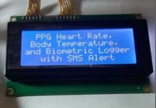
International Journal of Academy of Engineering Research and Theory (IJAERT), ISSN: 2545-5931
                                                                    Kureve T. Douglas, Tingir T. James, Kyari H. Jennifer
  Open Access                                                                                Vol. 1, Issue 1, Feb. 2021 , Pp 1-7

Three different stages were in involved in the design process and these are as follows: Input, Processing and Output Stages. The
functional block diagram is shown in Figure 1.

                                                   Figure 1: Functional block diagram

Input Stage
The input stage is made up of the PPG sensor (MAX30100) and Infrared Thermometer

MAX 30100 IC
The MAX30100 is an integrated pulse oximetry and heart-rate monitor sensor solution. It combines two LEDs, a photodetector,
optimized optics, and low-noise analog signal processing to detect pulse oximetry and heart-rate signals.. The MAX30100 operates
from 1.8V and 3.3V power supplies and can be powered down through software with negligible standby current, permitting the
power supply to remain connected at all times (Maxim Integrated, 2020). The signals from the MAX30100 are sent to the
Microcontroller for processing.

MLX90614 Module
The MLX90614 is an infrared thermometer for non-contact temperature measurements. Both the IR sensitive thermopile detector
chip and the signal conditioning ASIC are integrated in the same TO-39 can. Integrated into the MLX90614 are a low noise
amplifier, 17-bit ADC and powerful DSP unit thus achieving high accuracy and resolution of the thermometer (Melexis, 2020).
The sensor can be configured, the digital output to be Pulse Width Modulation (PWM). As a standard, the 10-bit PWM is
configured to continuously transmit the measured temperature in range of -20 to 120°C, with an output resolution of 0.14°C. The
sensor works well with embedded systems hence its use in the design. The temperature values are sent to the controller. The
system measures both the ambient temperature and the temperature of the body.

Processing Stage
The Aduino UNO handles all the activities in this stage.

Arduino UNO
The Arduino UNO is an open-source microcontroller board based on the microchip ATmega328P microcontroller. The board is set
equipped with sets of digital and analog input/output (I/O) pins that may be interfaced to various expansion boards and other
circuits. The board has 14 digital pins which 6 provides PWM, 6 analog pins and programmable with Arduino IDE (Integrated
Development Environment) via a type B USB cable. It can be powered by the USB cable or an external 9-volt battery, though it
accepts voltage between 7 and 20volts. It has a flash memory of 32KB of which 0.5KB used by boot loader, SRAM is 2KB,
EEPROM is 1KB with a clock speed of 16MHz. The microcontroller Timer counts the number of pulses (                _      ) entering
the microcontroller within a given period,     . The heart-rate of the user HR (in beats per minute), is determined using:

                                     _         ×
                      −       =                    (% &)                                                          (1)
                                         !"#

The period of measurement (        ) is 30 seconds. Oxygen saturation level SpO2 of a user is determined using,

                          +,-.
              ( )2 =                                                                                              (2)
                       +,/+,-.

Hemoglobin with oxygen molecules is considered as oxygenated hemoglobin( %)0 ). When it is carrying less oxygen molecules
then it is considered reduced (Hb). PWM output of MLX90614 can be configured in two modes – single data transmission and
                                                                       ~2~
http://perfectengineeringassociates.com                                                                           http://ijari.org.ng
International Journal of Academy of Engineering Research and Theory (IJAERT), ISSN: 2545-5931
Kureve T. Douglas, Tingir T. James, Kyari H. Jennifer
Open Access Vol. 1, Issue 1, Feb. 2021 , Pp 1-7
dual data transmission. For the average value to be useful the single PWM output format is required. It has the timings shown
below: T is the PWM period, t1 is starting buffer (always high, with a duration which is always 12.5% of the period), t2 is the data
band, taking an additional 0 to 50% of the period. t3 is the error signaling band (25% of the period). The temperature reading can
be calculated from the signal timing using:
0 .
=1 ( 234 − 25 )6 + 25 (3)
The values are sent to the output devices. Equation (1) is to determine the heart-rate of a user in beats per minute (bpm), Equation
(2) is to determine the SpO2 level and in Equation (3), T is the PMW period, t1 is the starting buffer, t2 is the data band and t3 is
the Error signaling band (25% of the period).
Output Stage
The output of the system includes the liquid crystal display and the piezo buzzer alarm.
The 20 by 4 LCD
The 20 by 4 liquid crystal display is a flat panel display that uses the light modulating properties of liquid crystals, hence inducing
changes in its optical properties. The 20 by 4 is a 20 character by 4 line displays, thus, a total of 80 characters can be displayed at
any given instance of time. It has two registers; command/instruction register which stores command instructions given to the LCD
and data register which stores the data to be displayed on the LCD. The 20 by 4 LCD displays the value of the heart-rate in bpm,
the Spo2 in percentage; it also displays instruction and initialization processes of the system.
Buzzer
A buzzer or beeper is an audio signaling device, which may be mechanical, electromechanical or electronic. Its basic components
are a coil and piezo-material which it uses to create a buzz or twit. The microcontroller is programmed to send a signal to the
output pin configured for buzzer when the heart-rate exceeds 100 beats per minute or the SpO2 content is below 93%. The
complete schematic circuit diagram is shown in Figure 2
Figure 2: Complete schematic circuit diagram of the system
Software and Flow Chart
The open-source Arduino Software (IDE) was used to write the code and upload it to the board. It can run on Windows, Mac OS X
and Linux. The flowchart for the code is shown in Figure 3
~3~
http://perfectengineeringassociates.com http://ijari.org.ngInternational Journal of Academy of Engineering Research and Theory (IJAERT),
(IJAERT ISSN: 2545-5931
Kureve T. Douglas, Tingir T. James, Kyari H. Jennifer
Open Access Vol 1, Issue 1, Feb. 2021 , Pp 1-7
Vol.
Figure 3: Flow chart of the system.
Results and Discussion
From Figure 4, the procedure of the system is shown on its display. The system was tested on 15 subjects and results were
obtained. The heart-rate
rate was calibrated using a Littmann’s stethoscope, Pulse Oximeter device was calibrated an EMS 7000 Pulse
Oximeter, while the temperature
rature measurements were calibrated using the Hti Digital Thermometer. The results are shown in
Table 1. The results obtained compared favorably well with that of standard devices.
1a
~4~
http://perfectengineeringassociates.com http://ijari.org.ngInternational Journal of Academy of Engineering Research and Theory (IJAERT), ISSN: 2545-5931
Kureve T. Douglas, Tingir T. James, Kyari H. Jennifer
Open Access Vol. 1, Issue 1, Feb. 2021 , Pp 1-7
1b
1c
1d
1e
~5~
http://perfectengineeringassociates.com http://ijari.org.ngInternational Journal of Academy of Engineering Research and Theory (IJAERT), ISSN: 2545-5931
Kureve T. Douglas, Tingir T. James, Kyari H. Jennifer
Open Access Vol. 1, Issue 1, Feb. 2021 , Pp 1-7
1f
1g
Figure 4 (a – g): Heart-rate procedure on LCD
Table 1: Device results calibrated against standard devices.
It should be noted that in Table 1, HR (BPM) is the heart-rate in beats per minute, HR (stethoscope) is the heart-rate measured
from stethoscope, HR (error) is the error obtained from heart-rate measurement, SPO2 is the blood oxygen concentration, Temp is
the temperature, Hti digital thermometer is the body infrared thermometer and Temp error is the error obtained from temperature
measurement (0C).
~6~
http://perfectengineeringassociates.com http://ijari.org.ngInternational Journal of Academy of Engineering Research and Theory (IJAERT), ISSN: 2545-5931
Kureve T. Douglas, Tingir T. James, Kyari H. Jennifer
Open Access Vol. 1, Issue 1, Feb. 2021 , Pp 1-7
Conclusion
The major advantages to be derived from this study are detection of tachycardia heart condition which is achieved through the
incorporation of buzzer and LED system when the measured heart-rate exceeds a hundred beats per minute (100BPM) or SpO2
level drop below 93%. In addition to this is the measurement of body temperature through a wireless and contactless infrared
thermometer. In conclusion, in this study, heart-rate, pulse oximeter and temperature monitoring device was designed and
implemented successfully. The results obtained were compared to standard devices and the errors obtained were within acceptable
limit. The device could be used as alternative in health care centers and could also incorporate a GSM Module to send messages to
a physician and finally biometric can be introduced to be used as an identifier to know the specific user.
References
Abe, H., Semba, H. and Takeda, N. (2017) The Roles of Hypoxia Signaling in the Pathogenesis of Cardiovascular Disease
Journal of Atherosclerosis and Thrombosis. 24(9): 884–894
Babiker S. F., Abdel-Khair L. E. and Elbasheer S. M. (2011). “Microcontroller Based Heart Rate Monitor using Fingertip
Sensors”, University of Khartoum Engineering Journal (UofKEJ), Vol. 1 (2): pp 47-51.
Cömert B., Istanbullu A. and Turhal U. (2014). “Low Cost and Portable Heartbeat Rate Measurement from the Finger”, The 5th
International Symposium on Sustainable Development, Sarajevo, Bosnia and Herzegovina: pp 197-204.
Khoustubh P. (2018) Blood Oxygen Level Monitoring System [online] available at :
https://www.skyfilabs.com/project-ideas/blood-oxygen-level-monitoring-system
Maxim Integrated (2020) MAX30100 [online] available at:
https://www.maximintegrated.com/en/products/sensors/MAX30100.html
Mayo Clinic (2020) Tachycardia. [Online] available at:
https://www.mayoclinic.org/diseases-conditions/tachycardia/symptoms-causes/syc-20355127
Medline Plus (2020) Body Temperature Norms [online] available at:
https://medlineplus.gov/ency/article/001982.htm#:~:text=The%20average%20normal%20body%20temperature,by%20an
%20infection%20or%20illness.
Melexis (2020) Digital plug & play infrared thermometer in a TO-can [online] available at :
https://www.melexis.com/en/product/MLX90614/Digital-Plug-Play-Infrared-Thermometer-TO-Can
(Copyright @ 2021 IJAERT)
~7~
http://perfectengineeringassociates.com http://ijari.org.ngYou can also read