IMX RT1052 Developer's Kit Program Development Guide - Get Up-and-Running Quickly and Start Developing Your Application On Day 1! - Embedded Artists
←
→
Page content transcription
If your browser does not render page correctly, please read the page content below
iMX RT1052 Developer’s Kit - Program Dev. Guide
Copyright 2018 © Embedded Artists AB

                                       iMX RT1052 Developer’s Kit
                                       Program Development Guide

                           Get Up-and-Running Quickly and
                           Start Developing Your Application On Day 1!

                                                                         EA2-USG-1208 Rev A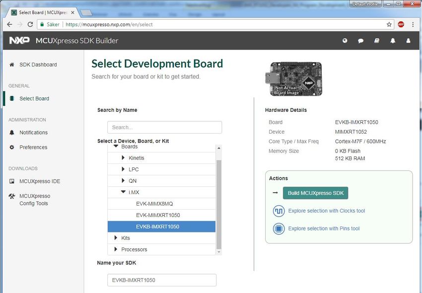
iMX RT1052 OEM Developer’s Kit - Program Development Guide                                                      Page 2

                        Embedded Artists AB
                        Jörgen Ankersgatan 12
                        211 45 Malmö
                        Sweden
                        http://www.EmbeddedArtists.com

                        Copyright 2018 © Embedded Artists AB. All rights reserved.
                        No part of this publication may be reproduced, transmitted, transcribed, stored in a retrieval system, or
                        translated into any language or computer language, in any form or by any means, electronic, mechanical,
                        magnetic, optical, chemical, manual or otherwise, without the prior written permission of Embedded Artists
                        AB.

                        Disclaimer
                        Embedded Artists AB makes no representation or warranties with respect to the contents hereof and
                        specifically disclaim any implied warranties or merchantability or fitness for any particular purpose.
                        Information in this publication is subject to change without notice and does not represent a commitment on
                        the part of Embedded Artists AB.

                        Feedback
                        We appreciate any feedback you may have for improvements on this document. Please send your
                        comments to support@EmbeddedArtists.com.

                        Trademarks
                        All brand and product names mentioned herein are trademarks, services marks, registered trademarks, or
                        registered service marks of their respective owners and should be treated as such.

Copyright 2018 © Embedded Artists AB
iMX RT1052 OEM Developer’s Kit - Program Development Guide                                           Page 3

                                             Table of Contents
                                              1 Document Revision History                                             5

                                              2 Get Started with Program Development                                  6
                                              2.1     Downloading and Installing MCUXpresso SDK from NXP               6
                                              2.2     Modify the SDK to Support iMX RT1052 Developer's Kit            11
                                              2.3     SDK Project Comments                                            11
                                              2.3.1    USB Examples                                                   11
                                              2.3.2    Network Examples                                               11
                                              2.4     Getting Started With a Specific IDE                             12

                                              3 Getting Started with Keil uVision/MDK and SDK                         13
                                              3.1     Install CMSIS Device Pack                                       13
                                              3.2     Build an Example Application                                    13
                                              3.3     Run an Example Application                                      14
                                              3.4     Selecting Build Target                                          16
                                              3.5     Configuring Flash Algorithm                                     17
                                              3.6     Build Output                                                    18

                                              4 Getting Started with Keil uVision/MDK and RTE                         19
                                              4.1     Install CMSIS Device Pack                                       19
                                              4.2     Build an Example Application                                    20
                                              4.3     Run an Example Application                                      21
                                              4.4     Selecting Build Target                                          23
                                              4.5     Configuring Flash Algorithm                                     24
                                              4.6     Build Output                                                    25
                                              4.7     Working with RTE                                                26

                                              5 Getting Started with IAR Embedded Workbench                           27
                                              5.1     Build an Example Application                                    27
                                              5.2     Run an Example Application                                      28
                                              5.3     Configuring Flash Algorithm                                     29
                                              5.4     Build Output                                                    30

                                              6 Getting Started with NXP MCUXpresso IDE                               32
                                              6.1     Install the SDK                                                 32
                                              6.2     Build an Example Application                                    32
                                              6.3     Run an Example Application                                      36
                                              6.4     Build Output                                                    37

                                              7 Debug Interface                                                       39
                                              7.1     J-LINK/J-TRACE Support                                          40
                                              7.1.1    Install J-LINK Software                                        40
                                              7.1.2    MCUXpresso 10.2.1                                              40

Copyright 2018 © Embedded Artists AB
iMX RT1052 OEM Developer’s Kit - Program Development Guide                                Page 4

                                              7.1.3    Keil uVision v5.25.2                                40
                                              7.1.4    J-LINK/J-TRACE Troubleshooting                      42

                                              8 Standalone Program Download                                43
                                              8.1     Install the Required Software                        43
                                              8.2     Prepare the Program to Flash                         44
                                              8.3     Download the Program                                 44

                                              9 Terminal Application Setup                                 46
                                              9.1     UART-to-USB Bridge                                   46
                                              9.2     Terminal Application on the PC                       46
                                              9.2.1    Tera Term Terminal Emulation Application            47
                                              9.2.2    PuTTY terminal emulation application                48

                                              10 Booting from External Memory                              49

                                              11 Things to Note                                            52
                                              11.1     ESD Precaution                                      52
                                              11.2     General Handling Care                               52
                                              11.3     OTP Fuse Programming                                52
                                              11.4     Further Information                                 53

                                              12 Disclaimers                                               54
                                              12.1     Definition of Document Status                       55

Copyright 2018 © Embedded Artists AB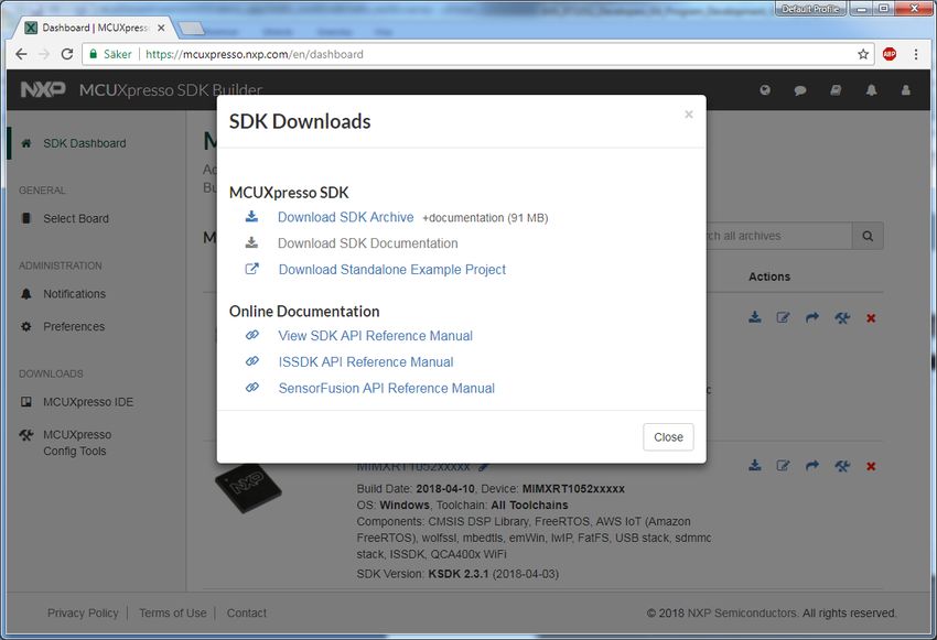
iMX RT1052 OEM Developer’s Kit - Program Development Guide                                                 Page 5

                        1 Document Revision History
                        Revision       Date         Description
                        PA1            2018-01-02   First released version.
                        PA2            2018-01-03   Added description of build targets and Mfgtool.
                        PA3            2018-04-16   Updated instructions for SDK and different IDEs.
                        PA4            2018-05-22   Updated instructions for MCUXpresso.
                        PA5            2018-06-25   Updated instructions to match version 2.4.0 of the SDK. Changed
                                                    description for IAR Workbench as flash driver is now included in the
                                                    IDE.
                        PA6            2018-08-24   Reorganize the document structure. Updated instructions around
                                                    Mfgtool and flashing. Added J-LINK/J-TRACE instructions.
                        PA7            2018-09-10   Added information about CMSIS-PACK for Keil uVision

Copyright 2018 © Embedded Artists AB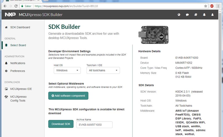
iMX RT1052 OEM Developer’s Kit - Program Development Guide Page 6
2 Get Started with Program Development
This chapter contains information about how to get started with program development on the iMX RT1052
Developer's Kit. It also contains information about program download, i.e., how to flash the EcoXiP flash
memory.
To start program development you need the following things, all of them:
1. MCUXpresso SDK - this is a package of sample software that must be downloaded from NXPs
website. You need to create an account on NXP's website for this.
2. Apply a zip-file to the SDK with projects specific to the iMX RT1052 Developer's Kit. The zip-file is
downloaded from the iMX RT1052 Developer's Kit support page on Embedded Artists' website.
3. Integrated Development Environment (IDE)
a. As of August 2018, NXP MCUXpresso, Keil uVision/MDK and IAR Embedded
Workbench supports direct flash programming of the EcoXiP.
b. Programming of the EcoXiP flash is also supported via NXP's Mfgtool standalone
application but it is not a suitable tool to use during program development.
4. JTAG probe to be able to download the application to SRAM, SDRAM or the EcoXiP flash memory
and in general to be able to debug - set breakpoints, inspect memory, etc.
a. The low-cost LPC-Link2 is an excellent choice. Keil ULINK2 and ULINKplus, as well as
Segger JLINK, are also excellent debug probes.
b. Technically it is possible to program/flash the EcoXiP without a JTAG probe (via NXP's
Mfgtool application), but it is strongly recommended to use the proper tool for debugging -
i.e., use a JTAG probe!
5. And of course the iMX RT1052 Developer's Kit!
2.1 Downloading and Installing MCUXpresso SDK from NXP
This section will walk you through the installation of the MCUXpresso SDK, which is a package of sample
software projects (with device drivers and peripheral examples and demos) that will get you started
immediately with your i.MX RT software development. Note that even though the name of the SDK suggests
the code package is for the MCUXpresso IDE, the sample projects have project files for other IDEs as well,
such as Keil uVision/MDK, IAR Embedded Workbench, and more.
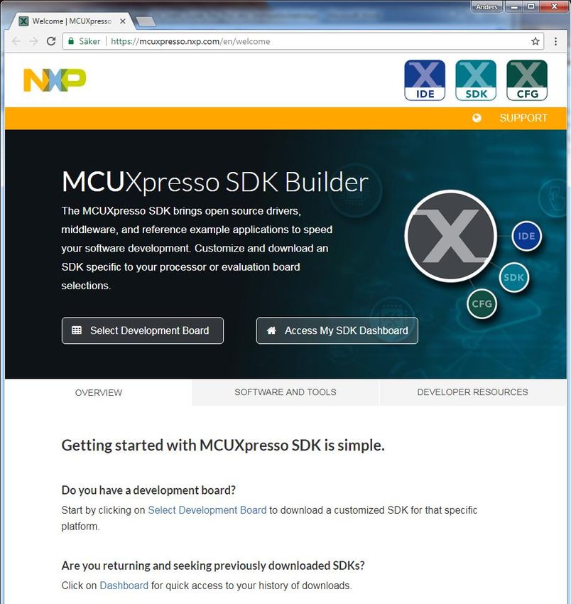
First download the MCUXpresso SDK by following this url: https://mcuxpresso.nxp.com/en/welcome This is
the online SDK builder that makes sure you will get the latest version of the software.
Note that some details in the screen dumps in this section might change over time, but the basic
walkthrough steps are the same.
You will need to login to your NXP account. Then click on Select Development Board.
Copyright 2018 © Embedded Artists AB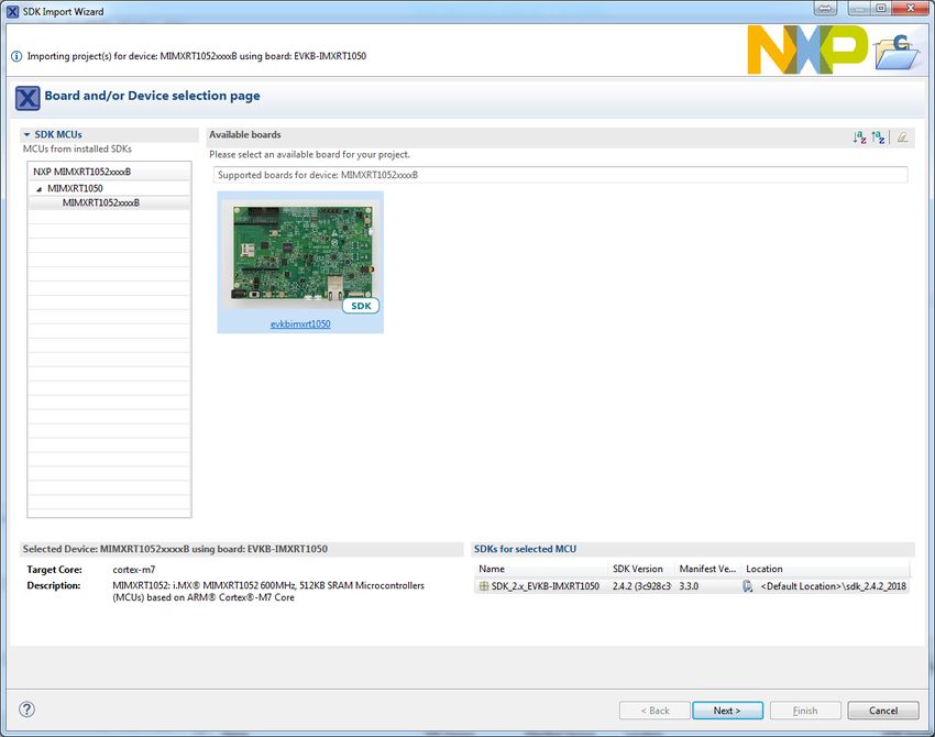
iMX RT1052 OEM Developer’s Kit - Program Development Guide   Page 7

                        Figure 1 – MCUXpresso SDK Builder

Copyright 2018 © Embedded Artists AB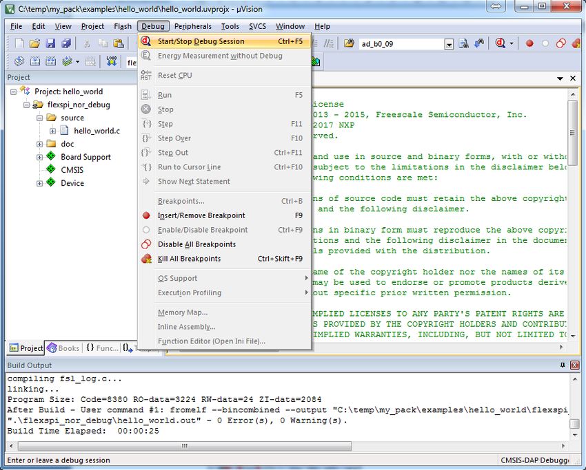
iMX RT1052 OEM Developer’s Kit - Program Development Guide Page 8
Then select the Boards i.MX EVKB-MIMXRT1050. This is the NXP evaluation board, but most of the
samples will work unmodified on the iMX RT1052 Developer's Kit. Note that there are two different versions
of the MIMXRT1050 EVK - EVK and EVKB. It is the latter that shall be selected because that supports i.MX
RT1052 silicon revision A1.
Figure 2 – MCUXpresso SDK Builder - Select Development Board
Copyright 2018 © Embedded Artists AB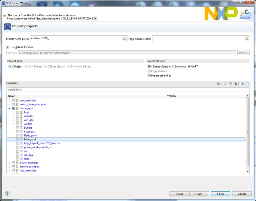
iMX RT1052 OEM Developer’s Kit - Program Development Guide                                                     Page 9

                        After selecting the NXP EVK, click on the Build MCUXpresso SDK button.

                        Figure 3 – MCUXpresso SDK Builder - Build MCUXpresso SDK

                        As a final step before downloading, select All Toolchains under the Toolchain/IDE dropdown list. Then press
                        Download SDK button. This will give you a complete package with all software.

                        Figure 4 – MCUXpresso SDK Builder - SDK Builder

                        Also agree to the Software Terms and Conditions by clicking on the I Agree button.

Copyright 2018 © Embedded Artists AB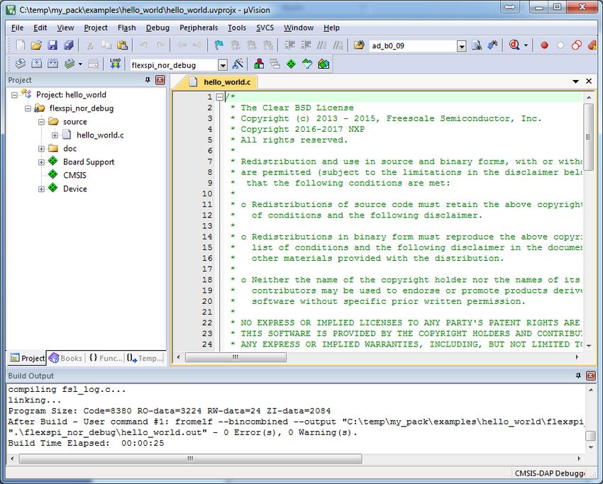
iMX RT1052 OEM Developer’s Kit - Program Development Guide                                                            Page 10

                        Download of a (about) 91MByte zip-file will begin.

                        Figure 5 – MCUXpresso SDK Builder - SDK Downloads

                        Save the file on your computer. Note the download location. As of August 2018, the file name is
                        SDK_2.4.2_EVKB-MIMXRT1050.zip, but the version number (i.e., 2.4.2) will likely increment
                        over time. Extract the content of the zip-file to the desired installation location in your file system. Note that
                        the installation root shall have a short path. For example: c:\NXP_SDK\

Copyright 2018 © Embedded Artists AB
iMX RT1052 OEM Developer’s Kit - Program Development Guide Page 11
2.2 Modify the SDK to Support iMX RT1052 Developer's Kit
This section describes how to download and modify the previously installed SDK to be compatible with the
specific for the features of the iMX RT1052 Developer's Kit, like the EcoXiP.
If you have not yet created a support account on Embedded Artists' website, do so. Also register the product
serial key that came along with the iMX RT1052 Developer's Kit (on a flyer inside the box). This gives
access to a specific support page for the iMX RT1052 Developer's Kit.
The SDK supports hyper flash but the iMX RT1052 Developer's Kit has EcoXip flash from Adesto. Ideally
the EcoXip flash driver should be placed in a new file with _ecoxip in the name but that would require
changes to every project for every IDE in the SDK and that is a huge task. The solution is instead to replace
the file content but keep the filename. This way none of the projects have to be modified.
Download the zip-file from above-mentioned support page. The name of the file is:
ea_files__for_SDK.zip
Unpack the downloaded zip-file in a temporary directory, for example: c:/temp/ea_files
Copy
c:/temp/ea_files/evkbimxrt1050_flexspi_nor_config.c
to
/devices/MIMXRT1052/xip/
replacing the existing file. This will add support for the EcoXip.
2.3 SDK Project Comments
The MCUXpresso SDK comes with a long list of example application code. To see what's available, browse
to the boards folder of your SDK installation and select your board:
/boards/evkbimxrt1050
Only use the projects found under this sub-directory.
To learn more about specific example code, open the readme.txt file in an example’s directory.
The following sections will describe some projects that will require extra configuration to work.
2.3.1 USB Examples
The USB interface is different on the NXP EVK that the SDK is for and the iMX RT1052 Developer's Kit. The
USB examples all have a block of code (most of the time in app.h) to define the CONTROLLER_ID like this:
#if ((defined USB_HOST_CONFIG_KHCI) && (USB_HOST_CONFIG_KHCI))
#define CONTROLLER_ID kUSB_ControllerKhci0
#endif /* USB_HOST_CONFIG_KHCI */
#if ((defined USB_HOST_CONFIG_EHCI) && (USB_HOST_CONFIG_EHCI))
#define CONTROLLER_ID kUSB_ControllerEhci0
#endif /* USB_HOST_CONFIG_EHCI */
#if ((defined USB_HOST_CONFIG_OHCI) && (USB_HOST_CONFIG_OHCI))
#define CONTROLLER_ID kUSB_ControllerOhci0
#endif /* USB_HOST_CONFIG_OHCI */
#if ((defined USB_HOST_CONFIG_IP3516HS) && (USB_HOST_CONFIG_IP3516HS))
#define CONTROLLER_ID kUSB_ControllerIp3516Hs0
#endif /* USB_HOST_CONFIG_IP3516HS */
All that is needed is to change the 0 (marked in red above) to 1.
2.3.2 Network Examples
The iMX RT1052 Developer's Kit has an EEPROM with a unique id that can be used as MAC address in the
network examples, found in the demo_apps/lwip directory. Follow these steps to use it:
Copyright 2018 © Embedded Artists ABiMX RT1052 OEM Developer’s Kit - Program Development Guide Page 12
1. Start by copying the mac_addr.c and mac_addr.h files from the ea_files__for_SDK.zip
archive in section 2.2 into your project
2. Add the mac_addr.c file to the project. How this is done depends on the IDE but for Keil uVision,
right click on the source folder in the project and select Add existing files to group 'source'.
3. Add the I2C driver to the project the same way as in the previous step. The driver is called fsl_lpi2c
and can be found in the /devices/MIMXRT1052/drivers/ folder.
4. Add #include "mac_addr.h" to main.c after the other include statements
5. Find the declaration in the main.c file that looks like this:
ethernetif_config_t fsl_enet_config0 = {
.phyAddress = EXAMPLE_PHY_ADDRESS,
.clockName = EXAMPLE_CLOCK_NAME,
.macAddress = configMAC_ADDR,
};
and add this line after it:
MAC_Read(fsl_enet_config0.macAddress);
Now the program will attempt to read the MAC address from the EEPROM before the LWIP stack is
initialized.
2.4 Getting Started With a Specific IDE
The following chapters will describe how to get started with a number of different IDEs.
Chapter 3 describes Keil uVision.
Chapter 4 describes IAR Embedded Workbench.
Chapter 6 describes NXP MCUXpresso.
Copyright 2018 © Embedded Artists ABiMX RT1052 OEM Developer’s Kit - Program Development Guide Page 13
3 Getting Started with Keil uVision/MDK and SDK
This section is a guide to open, build and debug an example application using Keil uVision/MDK with the
SDK as installed in chapter 2 . It is assumed that you have this development environment installed on your
computer.
Following the instructions in this section will make it possible to run all examples in the downloaded SDK.
Note that none of the examples use the RTE (Run-Time Environemnt) feature of the Keil uVision/MDK. The
use of RTE is described in chapter 4 .
Make sure the version of uVision is v5.25.2, or later. Else there is no support for flash
download/programming to the EcoXiP flash memory directly.
3.1 Install CMSIS Device Pack
After the MDK tools are installed, Cortex Microcontroller Software Interface Standard (CMSIS) device packs
must be installed to fully support the device from a debug perspective. These packs include things such as
memory map information, register definitions and flash programming algorithms. Follow these steps to install
the IMXRT105x CMSIS pack.
1. Start Keil uVision
2. Start the Pack Installer tool with this button on the toolbar:
3. Browse to the MIMXRT1052 in the device tree (NXP→MIMXRT1052→MIMXRT1052xxxxB) and
then click the Install button next to the package name. Note that the button in the image below has
"Up to date" as the package has already been installed.
3.2 Build an Example Application
The following steps will guide you through opening the hello_world application. These steps may change
slightly for other example applications as some of these applications may have additional layers of folders in
their path.
Copyright 2018 © Embedded Artists ABiMX RT1052 OEM Developer’s Kit - Program Development Guide Page 14
1. If not already done, open the desired example application workspace in:
/boards/eaimxrt1052//
/mdk
The workspace file is named .uvmpw, so for this specific example, the actual
path is:
/boards/eaimxrt1052/demo_apps/
hello_world/mdk/hello_world.uvmpw
2. To build the demo project, select the "Rebuild" button, highlighted in red.
3. The build will complete without errors.
3.3 Run an Example Application
To download and run the application, perform these steps:
4. Connect the debug probe to development platform to your PC via USB cable. See chapter 7 for
details how to connect the debug probe.
5. Select the Debug menu and then Start/Stop Debug Session, or simply press Ctrl+F5.
The application will then be downloaded into SRAM.
Copyright 2018 © Embedded Artists ABiMX RT1052 OEM Developer’s Kit - Program Development Guide Page 15
6. Open the terminal application on the PC, such as TeraTerm or PuTTY, and connect to the debug
serial port number. Configure the terminal with 115200 baud, 8N1.
You can alter the baud rate be searching for the reference BOARD_DEBUG_UART_BAUDRATE
variable in file: board.h
7. Run the code by clicking the “Run” button (or tress F5) to start the application.
Copyright 2018 © Embedded Artists ABiMX RT1052 OEM Developer’s Kit - Program Development Guide Page 16
8. The hello_world application is now running and a banner is displayed on the terminal. If this is not
true, check your terminal settings and connections.
3.4 Selecting Build Target
A target is a variant of the project that for example can change compiler flags or dictate in what memory
region the program should execute. All projects have one or more targets as shown in the picture below.
Figure 6 – Build Targets in Keil uVision/MDK
The target name starts with the project name, hello_world in this case, and then the nomenclature as
outlined in the table below is used. Release targets have a higher compiler optimization degree making the
target less suitable for debugging.
sdram_debug The application runs in internal SRAM but with data in external
sdram_release SDRAM
sdram_txt_debug The application runs in external SDRAM but with data in internal
sdram_txt_release SRAM
debug The application runs in internal SRAM
release
flexspi_nor_debug The application runs in external flash, which must be
flexspi_nor_release programmed/flashed before use. Need extra configuration, see
section 3.5 .
Note that each of the targets have its own set of options so changing for example include path in one target
does not affect the other targets.
Copyright 2018 © Embedded Artists ABiMX RT1052 OEM Developer’s Kit - Program Development Guide Page 17
3.5 Configuring Flash Algorithm
To setup a project for storing/executing the application from the EcoXiP flash, select one of the
flexspi_nor_* targets, right click on the project and select Options for Target (or press
Alt+F7). Select the Debug tab and select Settings for the debugger. Then select the Flash Download tab.
Replace the existing driver with the EcoXiP flash driver as shown below.
Figure 7 – Keil uVision/MDK Flash Algorithm Settings
Copyright 2018 © Embedded Artists ABiMX RT1052 OEM Developer’s Kit - Program Development Guide Page 18
3.6 Build Output
Building a project results in one important file:
An *.out file (for example ea_demo.out) which is perfect when debugging or using the
debugger to flash the program
If the goal is to use the MfgTool to download the program (as explained in chapter 8 ) then another file is
more important:
An *.bin file (for example ea_demo.bin)
To get the *.bin file created automatically, add a User Command, as shown in the picture below. The
command is:
fromelf --bincombined --output "$L@L.bin" "!L"
Figure 8 – After Build Command to Create BIN File in Keil uVision/MDK
Copyright 2018 © Embedded Artists ABiMX RT1052 OEM Developer’s Kit - Program Development Guide Page 19
4 Getting Started with Keil uVision/MDK and RTE
This section is a guide to open, build and debug an example application using Keil uVision/MDK with the
Board Support Package (BSP) installed using the Pack Installer and not the SDK described in chapter 2 . It
is assumed that you have this development environment installed on your computer.
The BSP contains a small subset of all the examples available in the SDK. The main difference between the
SDK and the BSP examples is that the BSP examples use the Run-Time Environment (RTE) feature in Keil
uVision/MDK and the SDK doesn't.
The RTE is a way to manage software components (e.g. drivers, rtos, network stacks, usb stacks) to
add/remove features in a project without having to add each source file and include path individually.
The recommendation is to use the SDK unless you know exactly what you are doing. The use of the SDK is
described in chapter 3 .
Make sure the version of uVision is v5.25.2, or later. Else there is no support for flash
download/programming to the EcoXiP flash memory directly.
4.1 Install CMSIS Device Pack
After the MDK tools are installed, Cortex Microcontroller Software Interface Standard (CMSIS) device packs
must be installed to fully support the device from a debug perspective. These packs include things such as
memory map information, register definitions and flash programming algorithms. Follow these steps to install
the IMXRT105x CMSIS pack.
1. Start Keil uVision
2. Start the Pack Installer tool with this button on the toolbar:
3. Browse to the MIMXRT1052 in the device tree (NXP→MIMXRT1052→MIMXRT1052xxxxB) and
then click the Install button next to the package name. Note that the button in the image below has
"Up to date" as the package has already been installed.
Copyright 2018 © Embedded Artists ABiMX RT1052 OEM Developer’s Kit - Program Development Guide Page 20
4. Next click the Install button for the EmbeddedArtists::iMXRT1052_DevelopersKit_BSP
4.2 Build an Example Application
The following steps will guide you through opening the Hello World application. These steps may change
slightly for other example applications as some of these applications may have additional layers of folders in
their path.
1. Start Keil uVision
2. Start the Pack Installer tool with this button on the toolbar:
3. Browse to the MIMXRT1052 in the device tree (NXP→MIMXRT1052→MIMXRT1052xxxxB) and
then select the Examples tab
4. Click the Copy button next to the example to test it. In this case the Hello World example.
Copyright 2018 © Embedded Artists ABiMX RT1052 OEM Developer’s Kit - Program Development Guide Page 21
5. Select a location for the project files in the dialog that appears and then click OK.
6. A new uVision window will appear after a few seconds with the newly created project
7. To build the demo project, select the "Rebuild" button, highlighted in red.
8. The build will complete without errors.
4.3 Run an Example Application
To download and run the application, perform these steps:
1. Connect the debug probe to development platform to your PC via USB cable. See chapter 7 for
details how to connect the debug probe.
2. Select the Debug menu and then Start/Stop Debug Session, or simply press Ctrl+F5.
The application will then be downloaded into flash and started.
Copyright 2018 © Embedded Artists ABiMX RT1052 OEM Developer’s Kit - Program Development Guide Page 22
3. Open the terminal application on the PC, such as TeraTerm or PuTTY, and connect to the debug
serial port number. Configure the terminal with 115200 baud, 8N1.
You can alter the baud rate be searching for the reference BOARD_DEBUG_UART_BAUDRATE
variable in file: board.h
4. Run the code by clicking the “Run” button (or tress F5) to start the application.
5. The Hello World application is now running and a banner is displayed on the terminal. If this is not
true, check your terminal settings and connections.
Copyright 2018 © Embedded Artists ABiMX RT1052 OEM Developer’s Kit - Program Development Guide Page 23
4.4 Selecting Build Target
A target is a variant of the project that for example can change compiler flags or dictate in what memory
region the program should execute. All projects have one or more targets as shown in the picture below.
Figure 9 – Build Targets in Keil uVision/MDK
The default target is flexspi_nor_debug. The table below shows each of the targets. Release targets have
a higher compiler optimization degree making the target less suitable for debugging.
sdram_debug The application runs in internal SRAM but with data in external
sdram_release SDRAM
sdram_txt_debug The application runs in external SDRAM but with data in internal
sdram_txt_release SRAM
debug The application runs in internal SRAM
release
flexspi_nor_debug The application runs in external flash, which must be
flexspi_nor_release programmed/flashed before use. Need extra configuration, see
section 4.5 .
Note that each of the targets have its own set of options so changing for example include path in one target
does not affect the other targets.
Copyright 2018 © Embedded Artists ABiMX RT1052 OEM Developer’s Kit - Program Development Guide Page 24
4.5 Configuring Flash Algorithm
To setup a project for storing/executing the application from the EcoXiP flash, select one of the
flexspi_nor_* targets, right click on the project and select Options for Target (or press
Alt+F7). Select the Debug tab and select Settings for the debugger. Then select the Flash Download tab.
Replace the existing driver with the EcoXiP flash driver as shown below.
Figure 10 – Keil uVision/MDK Flash Algorithm Settings
Copyright 2018 © Embedded Artists ABiMX RT1052 OEM Developer’s Kit - Program Development Guide Page 25
4.6 Build Output
Building a project results in one important file:
An *.out file (for example ea_demo.out) which is perfect when debugging or using the
debugger to flash the program
If the goal is to use the MfgTool to download the program (as explained in chapter 8 ) then another file is
more important:
An *.bin file (for example ea_demo.bin)
To get the *.bin file created automatically, add a User Command, as shown in the picture below. The
command is:
fromelf --bincombined --output "$L@L.bin" "!L"
Figure 11 – After Build Command to Create BIN File in Keil uVision/MDK
Copyright 2018 © Embedded Artists ABiMX RT1052 OEM Developer’s Kit - Program Development Guide Page 26
4.7 Working with RTE
The Manage Run-Time Environment tool is started with a button on the toolbar:
The example projects are already configured correctly and it is possible to add more software components
by ticking the corresponding checkboxes.
There are a couple of very important things to note:
1) The Board Support must be "Embedded Artists" to get the drivers and templates as seen above
2) The Adesto EcoXip flash (ATXP032) must be selected otherwise applications will not start after
being flashed
3) If the watchdog driver (wdog) is used it must be selected from Board Support->Drivers->wdog and
not the Device->SDK Drivers->wdog. The reason is that the one in Board Support is patched to
work with the hardware.
The system for managing the RTE is described by Keil here:
http://www.keil.com/support/man/docs/uv4/uv4_ca_rtemanager.htm .
Copyright 2018 © Embedded Artists ABiMX RT1052 OEM Developer’s Kit - Program Development Guide Page 27
5 Getting Started with IAR Embedded Workbench
This section is a guide to open, build and debug an example application using IAR Embedded Workbench. It
is assumed that you have this development environment installed on your computer.
Make sure the version of Embedded Workbench is 8.30.1, or later. Else there is no support for flash
download/programming to the EcoXiP flash memory directly.
Every project that use the flash must be manually modified as they come pre-configured with the
wrong flash type. The instructions for this can be found in section 5.3 .
Many of the SRAM/SDRAM sample projects created for NXP's iMX RT1050 EVK will run on the iMX
RT1052 Developer's Kit, but not all of them.
5.1 Build an Example Application
The following steps will guide you through opening the hello_world application. These steps may change
slightly for other example applications as some of these applications may have additional layers of folders in
their path.
1. If not already done, open the desired example application workspace in:
/boards/evkmimxrt1050//
/iar
The workspace file is named .eww, so for this specific example, the actual path
is:
/boards/evkmimxrt1050/demo_apps/
hello_world/iar/hello_world.eww
2. Select the desired build target from the drop-down.
For this example, select the “flexspi_nor_debug” target.
The target name indicates from where the application is executing, see table below. The name also
indicates if it is a release or debug target. Release targets have a higher compiler optimization
degree making the target less suitable for debugging.
sdram_debug The application runs in internal SRAM but with data in external
sdram_release SDRAM
Copyright 2018 © Embedded Artists ABiMX RT1052 OEM Developer’s Kit - Program Development Guide Page 28
sdram_txt_debug The application runs in external SDRAM but with data in internal
sdram_txt_release SRAM
debug The application runs in internal SRAM
release
flexspi_nor_debug The application runs in external flash, which must be
flexspi_nor_release programmed/flashed before use. Need extra configuration, see
section 5.3 .
3. Note that the target has its own set of options so changing for example include path in one target
does not affect the other targets.
4. To build the demo application, click the “Make” button, highlighted in red below.
5. The build completes without errors.
5.2 Run an Example Application
To download and run the application, perform these steps:
1. Connect the debug probe to development platform to your PC via USB cable. See chapter 7 for
details how to connect the debug probe.
2. Open the terminal application on the PC, such as TeraTerm or PuTTY, and connect to the debug
serial port number. Configure the terminal with 115200 baud, 8N1.
You can alter the baud rate be searching for the reference BOARD_DEBUG_UART_BAUDRATE
variable in file: board.h
3. Click the "Download and Debug" button to download the application to the target.
4. The application is then downloaded to the target and automatically runs to the main() function.
5. Run the code by clicking the "Go" button to start the application.
Copyright 2018 © Embedded Artists ABiMX RT1052 OEM Developer’s Kit - Program Development Guide Page 29
6. The hello_world application is now running and a banner is displayed on the terminal. If this is not
true, check your terminal settings and connections.
5.3 Configuring Flash Algorithm
To setup a project for storing/executing the application from the EcoXiP flash:
1. Select one of the flexspi_nor_* targets, right click on the project and select Options (or press
Alt+F7).
2. Select the Debugger in the list and then the Download tab and select Settings for the debugger.
3. Select the two options as shown below (Verify download is optional)
The path in the box is
$TOOLKIT_DIR$\config\flashloader\NXP\FlashIMXRT1050_EVK_FlexSPI_EcoXiP.board
Copyright 2018 © Embedded Artists ABiMX RT1052 OEM Developer’s Kit - Program Development Guide Page 30
4. Select CMSIS DAP and then the Setup tab. Change Reset type to Software as shown here:
5.4 Build Output
Building a project results in one important file:
An *.out file (for example hello_world.out) which is perfect when debugging or using
the debugger to flash the program
If the goal is to use the MfgTool to download the program (as explained in chapter 8 ) then another file is
more important:
An *.bin file (for example hello_world.bin)
To get the *.bin file built automatically, open Project Options, select Output Converter in the list and then
configure like this.
Copyright 2018 © Embedded Artists ABiMX RT1052 OEM Developer’s Kit - Program Development Guide Page 31
Figure 12 – Generating bin file in IAR Embedded Workbench
Copyright 2018 © Embedded Artists ABiMX RT1052 OEM Developer’s Kit - Program Development Guide Page 32
6 Getting Started with NXP MCUXpresso IDE
This section is a guide to open, build and debug an example application using NXP MCUXpresso IDE. It is
assumed that you have this development environment installed on your computer.
Make sure the version of MCUXpresso is 10.2.1, or later. Else there is no support for flash
download/programming to the EcoXiP flash memory directly.
6.1 Install the SDK
MCUXpresso requires the SDK to be installed before it can be used. To do that start MCUXpresso and then
drag-n-drop the SDK folder (/) that was unpacked and modified in
section 2.2 on to the "Installed SDKs" tab in MCUXpresso:
During the installation MCUXpresso will make a copy of the folder that you drag-n-dropped so it is ok to
delete the / afterwards if you don't need it for one of the other IDEs.
6.2 Build an Example Application
The following steps will guide you through opening the hello_world application from the SDK.
1. Install the SDK as described in section 2.1 if you have not done so already
2. Click the "Import SDK example(s)…" link in the Quickstart Panel
Copyright 2018 © Embedded Artists ABiMX RT1052 OEM Developer’s Kit - Program Development Guide Page 33
3. Select the MIMXRT1050 and evkbimxrt1050. Click Next to go to the project selector.
Copyright 2018 © Embedded Artists ABiMX RT1052 OEM Developer’s Kit - Program Development Guide Page 34
4. Select the hello_world example and make sure to switch from Semihost to UART for the SDK
Debug Console then click Next to go to the Advanced Settings Page.
5. Now on the Advanced Settings page, Click the Edit… button next to the table with memory details
to open the Memory Configuration Editor:
Copyright 2018 © Embedded Artists ABiMX RT1052 OEM Developer’s Kit - Program Development Guide Page 35
6. Click and change the Size for BOARD_FLASH from 0x4000000 to 0x400000
7. Click and change the Driver for BOARD_FLASH from MIMXRT1050-EVK_S26KS512S.cfx to
MIMXRT1050-EcoXiP_ATXP032.cfx using the dropdown menu.
8. With all the changes made, click ok and then finish to have MCUXpresso complete the project
setup
Copyright 2018 © Embedded Artists ABiMX RT1052 OEM Developer’s Kit - Program Development Guide Page 36
9. Click Build in the Quickstart Panel
10. The program builds without errors
6.3 Run an Example Application
To download and run the application, perform these steps:
1. Connect the debug probe to development platform to your PC via USB cable. See chapter 7 for
details how to connect the debug probe.
2. Open the terminal application on the PC, such as TeraTerm or PuTTY, and connect to the debug
serial port number. Configure the terminal with 115200 baud, 8N1.
You can alter the baud rate be searching for the reference BOARD_DEBUG_UART_BAUDRATE
variable in file: board.h
Copyright 2018 © Embedded Artists ABiMX RT1052 OEM Developer’s Kit - Program Development Guide Page 37
3. Click the "Debug" button in the Quickstart Panel to download the application to the target.
4. The application is then downloaded to the target and automatically runs to the main() function.
5. Run the code by clicking the "Resume" button to start the application.
1. The hello_world application is now running and a banner is displayed on the terminal. If this is not
true, check your terminal settings and connections.
6.4 Build Output
Building a project results in one important file:
An *.axf file (for example hello_world.axf) which is perfect when debugging or using
the debugger to flash the program
If the goal is to use the MfgTool to download the program (as explained in section Fel! Hittar inte
referenskälla.below) then another file is more important:
An *.bin file (for example wohello_world.bin)
Copyright 2018 © Embedded Artists ABiMX RT1052 OEM Developer’s Kit - Program Development Guide Page 38
To get the *.bin file built automatically, select the Project->Properties menu and then select C/C++ Build,
select Settings and then the Build steps tab
Click the Edit button and then add the following in the dialog that appears:
arm-none-eabi-objcopy -v -O binary "${BuildArtifactFileName}"
"${BuildArtifactFileBaseName}.bin"
It should look like this:
Close and save. The *.bin file will be created the next time the project is built.
Copyright 2018 © Embedded Artists ABiMX RT1052 OEM Developer’s Kit - Program Development Guide Page 39
7 Debug Interface
It is strongly recommended to use a debug/JTAG probe during program development. The low-cost LPC-
Link2 is an excellent choice. Keil ULINK2 and ULINKplus, as well as Segger JLINK, are also excellent
debug probes.
There are two debug interface connectors available on the iMX OEM Carrier board:
J10 – this is a Cortex Debug connector. It is a 2x5 pos, 50 mil pitch connector without a shroud. Be
careful when inserting the debug probe cable. Position 1 is in specifically marked on the PCB
silkscreen. It is located in the lower right corner, see Figure 13 below.
The connector supports both the SWD and JTAG interfaces.
J11 – this is an ARM Debug connector. It is a 2x10 pos, 100 mil pitch connector with shroud.
Both connector are defined and supports both the SWD and JTAG type of debug interfaces.
Note that in order to enable the JTAG/SWD interface on the i.MX RT1052, JP5 shall not be
shorted/inserted.
Debug Ctrl Jumpers
JP5 - shall not be inserted
Debug Connectors
J11
Debug Connectors
J10
Note pos 1 in lower
right corner
Figure 13 – Debug Interfaces
Note that due to the errata on i.MX RT1052 rev A0 silicon, the debug probe I/O voltage MUST
follow the i.MX RT1052 I/O voltage.
The debug adapter must not drive any output higher than the Vcc/Vref voltage (and if that voltage
is zero, then the debug adapter must not drive any output signal). Vcc/Vref is pin 1 on both J10
and J11.
Make sure the debug probe does not have a fixed output voltage, but rather follow Vcc/Vref. If
using LPC-Link2 as debug interface, make sure there is NO jumper inserted in JP2 on the LPC-
Link2.
Copyright 2018 © Embedded Artists ABiMX RT1052 OEM Developer’s Kit - Program Development Guide Page 40
7.1 J-LINK/J-TRACE Support
This section describes the steps necessary to get the Segger J-TRACE to work with NXP MCUXpresso and
Keil uVision. The same instructions are likely to work for Segger J-LINK as well, but it has not been verified.
7.1.1 Install J-LINK Software
The software for the J-TRACE/J-LINK is installed in a central location (i.e. outside of the IDEs). The latest
version (v6.34) as of August 2018 have support for the iMX RT1052 but needs a configuration change to
support the EcoXiP flash memory:
1. Download and install the latest version of Segger's
software: https://www.segger.com/downloads/jlink/JLink_Windows.exe (v6.34, or later). The rest of
the steps will use as abbreviation for the folder that the driver was installed in, for
example c:\Program Files (x86)\SEGGER\JLink_V634b\
2. Open \JLinkDevices.xml
3. Search for MCIMXRT1052 to find entries (at the time this document was written there
were MCIMXRT1052, MCIMXRT1052xxxxA and MCIMXRT1052xxxxB)
4. In each of the entries, change
Loader="Devices/NXP/iMXRT105x/NXP_iMXRT105x_HyperFlash.elf"
to
Loader="Devices/NXP/iMXRT105x/NXP_iMXRT105x_QSPI.elf"
and save the file.
7.1.2 MCUXpresso 10.2.1
Chapter 6 describes how to import a project and set it up correctly for the Adesto EcoXip flash. It is
important that the flash algorithm is changed to MIMXRT1050-EcoXiP_ATXP032.cfx and that the flash size
is changed to 0x400000.
Build and then launch the debugger. MCUXpresso will detect the J-LINK / J-TRACE and configure itself
correctly.
7.1.3 Keil uVision v5.25.2
Chapter 6 describes how to import a project and set it up correctly for the Adesto EcoXip flash. It is
important that the flash algorithm is changed to MIMXRT105x EcoXiP Flash and that the flash size is
changed to 0x400000.
Change the Debugger from the default CMSIS-DAP to J-LINK / J-TRACE Cortex, as shown in picture below:
Copyright 2018 © Embedded Artists ABiMX RT1052 OEM Developer’s Kit - Program Development Guide Page 41
Figure 14 – Setting Debug Interface in Keil uVision
Open the settings dialog and change to the following settings:
Figure 15 – Configuring J-TRACE/J-LINK Interface in Keil uVision
Copyright 2018 © Embedded Artists ABiMX RT1052 OEM Developer’s Kit - Program Development Guide Page 42
Figure 16 – Configuring Flash Programming for J-TRACE/J-LINK Interface in Keil uVision
7.1.4 J-LINK/J-TRACE Troubleshooting
In some cases the IDE complains about not being able to connect to the target. This is most likely because
the program already running on the target is interfering. The solution is to put the hardware in ISP mode
before starting the flash/debug operation in the IDE. To do this:
1. Push and hold down the ISP enable button
2. Press the Reset button
3. Release the Reset button
4. Wait 1 seconds
5. Release the ISP enable button
Copyright 2018 © Embedded Artists ABiMX RT1052 OEM Developer’s Kit - Program Development Guide Page 43
8 Standalone Program Download
This chapter describe how to download an application to the iMX RT1052 OEM board without using the IDE.
Note that this section does not describe how to create the application code (create the application, compile
and link it). It is assumed that a binary file exist that represent the application program.
As a reminder, there are two basic methods for program download:
SWD/JTAG Debug Interface
Using this method, the application can be downloaded to internal SRAM, to external SDRAM or
external EcoXiP flash.
This method is tightly integrated with the Integrated Development Environment (IDE) used. Specific
scripts (and sometimes flash programming algorithms) must exist for the used IDE. Currently such
scripts and drivers exist for Keil uVision/MDK, NXP MCUXpresso and IAR Embedded Workbench.
For other IDEs, check supported functions.
o There are many different SWD/JTAG interfaces on the market. NXP has created the low-
cost LPC-LINK2, Keil has ULINK2/ULINKpro, Segger has J-LINK, etc.
ISP over USB Program Download
ISP is short for In-System Programming. The i.MX RT1052 MCU contains a bootloader in ROM
that can be enabled by pressing the ISP Enable push-button.
An application, Mfgtool2 provided by NXP, is needed on the PC for downloading and flashing the
application code. It is this method that will be described in this chapter.
The ISP over USB download is accomplished by using the Mfgtool application running on a PC.
Note the following limitations:
o The Mfgtool application is only available for Windows.
o The Mfgtool application must be downloaded from the NXP website for license reasons.
o The setup requires a couple of small modifications to work with the EcoXiP flash from
Adesto. These modifications are explained below.
8.1 Install the Required Software
First of all, download the "Flashloader i.MX-RT1050" application from NXP's website. It can be found under
the "Software & Tool" tab on the product page for the i.MX RT1050 MCU.
As of August 2018, the file name is Flashloader_i.MXRT1050_GA.zip. Extract the content of
the zip-file to the desired installation location in your file system. Note that the installation root shall have a
short path. For example: c:\NXP_SDK\
Modification #1:
1. Open the \Tools\mfgtools-rel\cfg.ini file
2. Replace this line:
name = MXRT105X-DevBoot
with
name = MXRT105x-DevBootSerialFlashXiP
Modification #2:
1. Open the \Tools\mfgtools-rel\Profiles\MXRT105X\OS Firmware\ucl2.xml file
Copyright 2018 © Embedded Artists ABiMX RT1052 OEM Developer’s Kit - Program Development Guide Page 44
2. Scroll down to a line that starts withiMX RT1052 OEM Developer’s Kit - Program Development Guide Page 45
bridge) or J1 (the 5V DC power jack).
The i.MX RT1052 MCU is now in ISP OTG mode.
3. Connect a micro-B USB cable between J12 and the PC.
4. Start the Mfgtool2.exe application on the PC. It is found here:
c:\NXP_SDK\\Tools\mfgtools-
rel\MfgTool2.exe.
If no i.MX RT1052 MCU in "ISP USB OTG" mode is detected, it will be flagged as "No Device
Connected".
When a device is detected it will be flagged as "HID-compliant device".
5. Click on the Start button. A progress bar will illustrate the download process. When ready click on
the Exit button.
6. Disconnect the USB cable from J12. If there is a (short circuit) jumper in J7, remove that.
7. Now power cycle the board, for example by pressing the reset push-button. If a correct image has
been flashed, it will now start executing.
Copyright 2018 © Embedded Artists ABiMX RT1052 OEM Developer’s Kit - Program Development Guide Page 46
9 Terminal Application Setup
This chapter contains information about the terminal connection that exist on the iMX OEM Carrier Board,
and how to setup a terminal application on the PC. The terminal connection connect UART1 of the i.MX
RT1052 to a virtual COM port over the USB interface available on J22. The terminal is commonly used
during program development.
9.1 UART-to-USB Bridge
The UART-to-USB bridge chip (FT230XS-R from FTDI) on the iMX OEM Carrier Board connects to UART
channel #1 on the i.MX RT1052. It exist to simplify connection to a PC because serial ports are not so
common any more, especially not on laptops. The USB port also offers the possibility to power the board.
There are two LEDs, transmit from the board (LED11) and receive to the board (LED10), that signal
communication activity.
See picture below for locating relevant components.
UART channel jumpers
JP3
Left position is receive to the i.MX RT
Right position is transmit from the i.MX RT
USB micro-B Connector
J22
Transmit LED
LED11
Receive LED
LED10
Figure 17 – UART-to-USB Bridge
9.2 Terminal Application on the PC
Begin by connecting the micro-B USB connector to J22, see picture above. Connect the other end of the
USB cable to the PC. The PC will typically immediately begin installing drivers automatically for the UART-
to-USB bridge that creates a Virtual COM port, if they are not already installed. If you have problems the
drivers can be downloaded from the links below:
http://www.ftdichip.com/Drivers/VCP.htm
http://www.ftdichip.com/Support/Documents/InstallGuides.htm
When the driver has been installed, a new COM port will listed under “Ports” in the Device Manager as
shown in Figure 18. Please note that the actual port number will most likely be different on your computer.
Figure 18 – Virtual COM port shown in device manager
Copyright 2018 © Embedded Artists ABiMX RT1052 OEM Developer’s Kit - Program Development Guide Page 47
The next step is to open a terminal application and attached it to the Virtual COM port that has just been
created. The baud rate should be 115200.
Some development environments/IDEs have a built-in terminal application that can be used. Sometimes it is
better to have a terminal application with more features. For increased flexibility, we recommend using any
of the two alternative terminal applications presented in the following sub-sections.
9.2.1 Tera Term Terminal Emulation Application
We recommend that you use Tera Term which can be downloaded and installed from either of the links
below.
https://ttssh2.osdn.jp/index.html.en
http://sourceforge.jp/projects/ttssh2/releases/
Launch Tera Term. The first time it launches, it will show you the following dialog. Select the serial option.
Assuming the USB cable is connected to the iMX OEM Carrier Board, there should be a COM port
automatically populated in the list.
Figure 19 – Tera Term New Connection Window
Configure the serial port settings (using the COM port number identified earlier) to 115200 baud rate, 8 data
bits, no parity and 1 stop bit. To do this, go to Setup Serial Port and change the settings.
Copyright 2018 © Embedded Artists ABiMX RT1052 OEM Developer’s Kit - Program Development Guide Page 48
Figure 20 – Tera Term Serial Port Setup
Verify that the connection is open. If connected, Tera Term will show something like below in its title bar.
Figure 21 – Tera Term Menu
9.2.2 PuTTY terminal emulation application
Alternatively you can use PuTTY. It is another commonly used terminal emulation application. PuTTY can
be downloaded and installed from the link below.
http://www.chiark.greenend.org.uk/~sgtatham/putty/download.html
Launch PuTTY by either double clicking on the *.exe file you downloaded or from the Start menu, depending
on the type of download you selected.
In the window that launches, select the Serial radio button and enter the COM port number that you
determined earlier. Also enter the baud rate, in this case 115200.
Figure 22 – PuTTY New Session Configuration
Click Open to open the serial connection. Assuming the FTDI cable is connected and you entered the
correct COM port, the terminal window will open. If the configuration is not correct, PuTTY will alert you.
Copyright 2018 © Embedded Artists ABiMX RT1052 OEM Developer’s Kit - Program Development Guide Page 49
10 Booting from External Memory
The i.MX RT1052 does not have any internal flash memory for storing the application. It has to be stored in
an external memory. On the iMX RT1052 OEM board, this external memory is a 4 MByte OctalSPI, called
EcoXiP ATXP032 from Adesto Technologies. The i.MX RT1052 MCU always boots (i.e., starts executing)
from this memory.
The EcoXiP memory is a low-power memory with a high-performance interface that operates in DDR
(Double Data Rate) mode at 131 MHz. The performance when executing directly from the EcoXiP memory
is very good. For more information about this product family, see
http://www.adestotech.com/products/ecoxip/
First, let's investigate the three use-cases when executing an application. The picture below illustrates the
first main use-case when executing an application.
i.MX RT1052 Memory from where
application is
Cortex-M7 Internal 1b - Execute from SRAM executed
core SRAM
1a - Copy application into SRAM during boot time
4 MByte 32 MByte
EcoXiP SDRAM
Figure 23 – i.MX RT1052 and EcoXiP - Executing from SRAM
1. The application is stored in the EcoXiP and the bootloader (inside the i.MX RT1052) copies it into
internal SRAM and then run from there.
a. The execution performance will be the highest in this setup.
b. CoreMark score 2600 / 3000 when running at 528 / 600 MHz
c. During program development the application is just downloaded to internal SRAM by the
debugger. There is no need to first download the application to the EcoXiP flash memory.
The address (in SRAM) where the application is downloaded is the same that it will be
copied to by the on-chip bootloader in a final deployed system.
Copyright 2018 © Embedded Artists ABiMX RT1052 OEM Developer’s Kit - Program Development Guide Page 50
The second use-case is illustrated below. It is the default option supported when compiling and building the
Xip targets.
i.MX RT1052 Memory from where
application is
Cortex-M7 Internal executed
core SRAM
4 MByte 32 MByte
EcoXiP SDRAM
Figure 24 – i.MX RT1052 and EcoXiP - Executing from EcoXiP
2. The application is stored in the EcoXiP and also executed from there. In this case, the internal
SRAM is probably too small for the application or is simply used for other things like data storage.
a. The execution performance will be about 2/3 of the performance when executing from the
EcoXiP (assuming 5% cache miss, which is typical).
b. CoreMark score 1736 / TBD when running at 528 / 600 MHz
c. During program development the application must be downloaded/flashed to the EcoXiP
memory before debugging actually starts. This is normally handled automatically by the
IDE (Integrated Development Environment).
Copyright 2018 © Embedded Artists ABiMX RT1052 OEM Developer’s Kit - Program Development Guide Page 51
The third use-case is just a mixture of the two main ones. Two, or more memories, are used for storing
executable code.
i.MX RT1052 Memory from where
application is
Cortex-M7 Internal executed
core SRAM
3b - Executing directly from all memories
3a - Copy application into SRAM and/or SDRAM
4 MByte 32 MByte
EcoXiP SDRAM
Figure 25 – i.MX RT1052 and EcoXiP - Executing from all memories
3. The third setup is a mixture of the two above. Part of the application is copied into SRAM and/or
SDRAM and part is executed directly from the EcoXiP. A reason for placing part of an application in
SRAM can be a need for highest performance for a data processing algorithm or a time critical
interrupt service routine.
a. Note that this is a more complicated system architecture. The application must implement
a dynamic loader that can copy code from the EcoXiP to SRAM, either on-demand or in a
pre-scheduled way. The linker script can be much more complicated because of this.
There is no general solution for this system solution. Every system must be individually
investigated in order to select and implement the best solution.
Copyright 2018 © Embedded Artists ABiMX RT1052 OEM Developer’s Kit - Program Development Guide Page 52
11 Things to Note
11.1 ESD Precaution
Please note that the iMX RT1052 OEM Board and iMX OEM Carrier Board come
without any case/box and all components are exposed for finger touches – and
therefore extra attention must be paid to ESD (electrostatic discharge)
precaution.
Make it a habit always to first touch the metal surface of one of the USB,
SD or Ethernet connectors for a few seconds with both hands before
touching any other parts of the boards. That way, you will have the same
potential as the board and therefore minimize the risk for ESD.
Never touch directly on the iMX RT1052 OEM Board and in general as little as possible on the iMX OEM
Carrier Board. The push-buttons on the iMX OEM Carrier Board have grounded shields to minimize the
effect of ESD.
Note that Embedded Artists does not replace boards that have been damaged by ESD.
11.2 General Handling Care
Handle the iMX RT1052 OEM Board and iMX OEM Carrier Board with care. The boards are not mounted in
a protective case/box and are not designed for rough physical handling. Connectors can wear out after
excessive use. The iMX OEM Carrier Board is designed for prototyping use, and not for integration into an
end-product.
For boards with LCD, do not exercise excessive pressure on the LCD glass area. That will damage the
display. Also, do not apply pressure on the flex cables connecting the LCD/touch screen. These are
relatively sensitive and can be damaged if too much pressure is applied to them.
Note that Embedded Artists does not replace boards where the LCD has been improperly handled.
11.3 OTP Fuse Programming
The i.MX RT1052 MCU has on-chip OTP fuses that can be programmed, see NXP documents
IMXRT1050CEC, .MX RT1050 Crossover Processors for Consumer Products - Data Sheet and
IMXRT1050RM, i.MX RT1050 Processor Reference Manual for details. Once programmed, there is no
possibility to reprogram them.
iMX RT1052 OEM Boards are delivered without any OTP fuse programming. It is completely up to the OEM
board user to decide if OTP fuses shall be programmed and in that case, which ones.
Note that Embedded Artists does not replace iMX RT1052 OEM Boards because of wrong OTP
programming. It’s the user’s responsibility to be absolutely certain before OTP programming and
not to program the fuses by accident.
Copyright 2018 © Embedded Artists ABiMX RT1052 OEM Developer’s Kit - Program Development Guide Page 53
11.4 Further Information
The following NXP documents are important reference documents and should be consulted for functional
details:
IMXRT1050CEC, .MX RT1050 Crossover Processors for Consumer Products - Data Sheet, latest
revision
IMXRT1050IEC, .MX RT1050 Crossover Processors for Industrial Products - Data Sheet, latest
revision
IMXRT1050RM, i.MX RT1050 Processor Reference Manual, latest revision
IMXRT1050CE, Chip Errata for the i.MX RT1050, latest revision
Note: It is the user's responsibility to make sure all errata published by the manufacturer are taken
note of. The manufacturer's advice should be followed.
AN12094, Power consumption and measurement of i.MXRT1050, latest revision
Copyright 2018 © Embedded Artists ABiMX RT1052 OEM Developer’s Kit - User’s Guide Page 54
12 Disclaimers
Embedded Artists reserves the right to make changes to information published in this document,
including, without limitation, specifications and product descriptions, at any time and without notice.
This document supersedes and replaces all information supplied prior to the publication hereof.
Customer is responsible for the design and operation of their applications and products using
Embedded Artists’ products, and Embedded Artists accepts no liability for any assistance with
applications or customer product design. It is customer’s sole responsibility to determine whether the
Embedded Artists’ product is suitable and fit for the customer’s applications and products planned, as
well as for the planned application and use of customer’s third party customer(s). Customers should
provide appropriate design and operating safeguards to minimize the risks associated with their
applications and products. Customer is required to have expertise in electrical engineering and
computer engineering for the installation and use of Embedded Artists’ products.
Embedded Artists does not accept any liability related to any default, damage, costs or problem which
is based on any weakness or default in the customer’s applications or products, or the application or
use by customer’s third party customer(s). Customer is responsible for doing all necessary testing for
the customer’s applications and products using Embedded Artists’ products in order to avoid a default
of the applications and the products or of the application or use by customer’s third party customer(s).
Embedded Artists does not accept any liability in this respect.
Embedded Artists does not accept any liability for errata on individual components. Customer is
responsible to make sure all errata published by the manufacturer of each component are taken note
of. The manufacturer's advice should be followed.
Embedded Artists does not accept any liability and no warranty is given for any unexpected software
behavior due to deficient components.
Customer is required to take note of manufacturer's specification of used components, for example
MCU, SDRAM and FLASH. Such specifications, if applicable, contains additional information that must
be taken note of for the safe and reliable operation. These documents are stored on Embedded Artists'
product support page.
All Embedded Artists’ products are sold pursuant to Embedded Artists’ terms and conditions of sale:
http://www.embeddedartists.com/sites/default/files/docs/General_Terms_and_Conditions.pdf
No license, express or implied, by estoppel or otherwise, to any intellectual property rights is granted
under this document. If any part of this document refers to any third party products or services it shall
not be deemed a license grant by Embedded Artists for the use of such third party products or
services, or any intellectual property contained therein or considered as a warranty covering the use in
any manner whatsoever of such third party products or services or any intellectual property contained
therein.
UNLESS OTHERWISE SET FORTH IN EMBEDDED ARTISTS’ TERMS AND CONDITIONS OF SALE
EMBEDDED ARTISTS DISCLAIMS ANY EXPRESS OR IMPLIED WARRANTY WITH RESPECT TO
THE USE AND/OR SALE OF EMBEDDED ARTISTS PRODUCTS INCLUDING WITHOUT
LIMITATION IMPLIED WARRANTIES OF MERCHANTABILITY, FITNESS FOR A PARTICULAR
PURPOSE (AND THEIR EQUIVALENTS UNDER THE LAWS OF ANY JURISDICTION), OR
INFRINGEMENT OF ANY PATENT, COPYRIGHT OR OTHER INTELLECTUAL PROPERTY RIGHT.
UNLESS EXPRESSLY APPROVED IN WRITING BY THE CEO OF EMBEDDED ARTISTS,
PRODUCTS ARE NOT RECOMMENDED, AUTHORIZED OR WARRANTED FOR USE IN MILITARY,
AIR CRAFT, SPACE, NUCLEAR, LIFE SAVING, OR LIFE SUSTAINING APPLICATIONS, NOR IN
PRODUCTS OR SYSTEMS WHERE FAILURE OR MALFUNCTION MAY RESULT IN PERSONAL
INJURY, DEATH, OR SEVERE PROPERTY OR ENVIRONMENTAL DAMAGE.
Resale of Embedded Artists’ products with provisions different from the statements and/or technical
features set forth in this document shall immediately void any warranty granted by Embedded Artists
Copyright 2018 © Embedded Artists ABYou can also read