INSTALLATION INSTRUCTIONS FOR DIFFERENTIAL PRESSURE SENSOR DELTA-P PART-NO. 60105 - ENGINESENS MOTORSENSOR GMBH
←
→
Page content transcription
If your browser does not render page correctly, please read the page content below
EngineSens Motorsensor GmbH
Mannheimer Str. 44 b
D-68519 Viernheim
www.enginesens.com
Installation instructions for
Differential Pressure Sensor
Delta-P
Part-No. 60105
Content:
Delta-P for Particulate Filter Applications
Technical Data
Electrical connection
Signal output
Lifetime
Installation Instructions
Tolerance
Tolerance expansion factor
Response Time
Limitations
Status March 2019
+49(0)6204 986 08 23 +49(0)6204 986 08 25 info@enginesens.com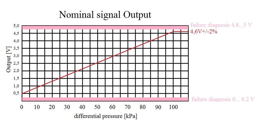
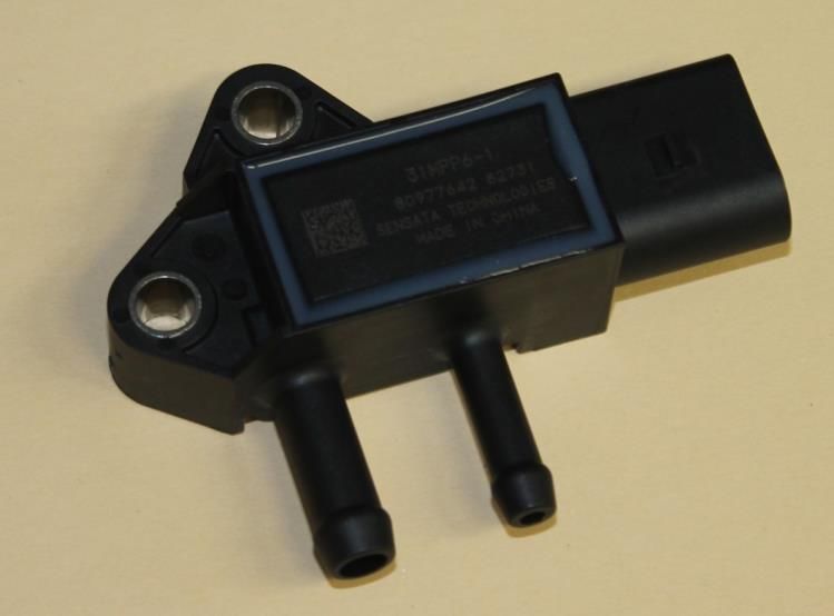
Differential Pressure Sensor Delta-P for Particulate Filter Applications The pressure sensor described underneath is mainly used to monitor the soot loading of a particulate filter on a diesel engine or gas turbine. The signal of the sensor is not sufficient to determine an optimized timing for regeneration of the DPF. It is part of a soot loading model that should be calculated permanently by the ECU. The sensor helps to determine the content of ashes remaining permanently in the filter. The soot loading model should be calculated in the background with the differential pressure as one of several inputs. Further input values are: engine load EGT (exhaust gas temperature) backpressure The triggering of the regeneration only based on the sensor signal is not recommended due to the following reasons: Increase of tolerances at high and low temperatures signal drift over lifetime filter overloading if sensor fails Usually the arithmetic soot loading model triggers the filter regeneration. Additionally time controlled regeneration should be implemented as a back-up system to avoid filter overloading in any case. During regeneration of an overloaded filter extremely high temperatures easily melt ceramic of metal filter systems. Fire Danger! The remaining ashes after regeneration cycles can be determined with the differential pressure sensor. The soot loading model can then be adjusted to the increasing ash content. The installation place of the sensor has to ensure that the gas temperature never exceeds 130°C. Cooling loops or prolonging the tube system helps to adjust the temperature management. The sensor has a very quick response time. An alternative application is monitoring the charger pressure for small chargers. Technical Data: Pressure measuring range (p1..p2): 100 kPa Operating temperature: -40°C...+135°C Energy consumption: 10 mA max. Electrical connection: The pinning is engraved in the connector housing: Pin 1: supply voltage Vcc +5V stabilized provided by ECU Pin 2: Ground Pin 3: Output 0....+5V The molded connector is similar to a standard connector by AMP/Tyco. For the opposite connection the following Tyco parts are required: 1 pcs 1813271-1 Body 3 pcs 964274-3 Terminal 3 pcs 964971-1 Grommet Adapting connectors to wires can optionally done by EngineSens Motorsensor according to your requirements. +49(0)6204 986 08 23 +49(0)6204 986 08 25 info@enginesens.com
Signal output
Linear output 0.5... 4.6 V depending on differential pressure. The range 0V…0.2V is reserved for a
diagnosis signal. In an analogue way the upper range 4.8V…5.0V is also reserved for sensor diagnosis.
The signal output is described by a linear function:
U = (0.82 x ∆p +10) x 0.05 [V/kPa]
Where:
U = signal output voltage [V] DC
∆p = differential pressure [kPa]
Example with ∆p = 70 kPa:
U=(0.82 x 70 kPa +10) x 0.05 V/kPa = (57,4 kPa +10) x 0.05 V/kPa = 67,4 kPa x 0.05 V/kPa = 3.37 V
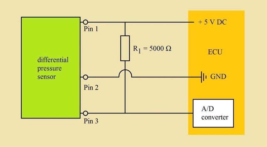
A pre-resistor is required if the sensor diagnosis should be activated. OBD capabilities and open circuit
can only be detected in conjunction with a 5 kΩ resistor. This resistor has to be applied as shown in the
sketch underneath.
Pull-up resistor
+49(0)6204 986 08 23 +49(0)6204 986 08 25 info@enginesens.com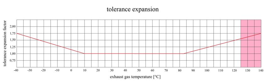
Lifetime
A differential pressure sensor is a part with limited lifetime. The pressure sensing cell consists of oxide
ceramics and is resistant against exhaust gases. Nevertheless a lifetime expectation of 120.000 km in
normal vehicle use can be considered as average.
Installation Instructions
Similar to an oxygen probe it has to be avoided that water and condensate can damage the interior of the
sensor. Therefore the sensor should be mounted with the hose connections showing downwards. The
flanged hose is to be routed within a cone of 20° from the vertical. Attention Off-Road-Vehicles: The
sensor must not be installed below wading depth of the vehicle. Avoid stone crush and water impact
areas!
The force of the hose on the housing must not exceed 40 N. During operation the pulling force of the hose
onto the socket is limited to 20 N per nozzle. The maximum gas temperature is limited to 130°C.
The untreated exhaust gas flows through a hose to the 8 mm port. The cleaned exhaust gas after filter
goes through a 6 mm hose to the low-pressure port. Hose clamps are used to fix the hoses. (Not included)
EngineSens Motorsensor offers precisely fitting formed hoses with aluminium cover as accessory (part-
no. 60102).
Differential pressure sensor with hoses part-no. 60102
Tolerance
Typical tolerances of a new product are in the range of 1.2%...1.6% of the output signal. At the end of
lifetime ca. 0.4% have to be added.
Tolerance expansion factor
In the range +10°C...+85°C the standard tolerance of 1,6% output is valid. In the range +85°C...+140°C
this tolerance increases continously from 1.0 (@ +85°C) to factor 1.75 (@ +140°C) of the standard
tolerance. In the range –40°C...+10°C it is vice versa. See diagram below.
Response Time
Response Time 90: < 10 ms
The response time is defined as time from zero to max. 90% pressure difference.
+49(0)6204 986 08 23 +49(0)6204 986 08 25 info@enginesens.com
Limitations The storage temperature is limited to +145°C. This temperature must never be exceeded even if the sensor is installed on the vehicle. It is important that the heat dissipation of a stopped hot engine does not overshoot the limits of the sensor probe. The maximum tolerable pressure difference is 200 kPa. The described sensor probe is used in many variants on diesel engines of the Volkswagen Group. These variants have all different fixing points. Our part offers the opportunity to use two different points fort he screw. This gives a lot of flexibility. Usually a screw M6x20 is sufficient to install the sensor properly. Always good success! Your Team EngineSens Motorsensor GmbH Mannheimer Str. 44 b D-68519 Viernheim Tel. +49(0)6204/98 60 823 Fax +49(0)6204/98 60 825 www.enginesens.com +49(0)6204 986 08 23 +49(0)6204 986 08 25 info@enginesens.com
You can also read