TinyOS Developers Guide - Volume 1 TINY OS GROUP UNIVERSITY OF CALIFORNIA, BERKELEY
←
→
Page content transcription
If your browser does not render page correctly, please read the page content below
1
                                     Volume

TINY OS GROUP
UNIVERSITY OF CALIFORNIA, BERKELEY
The Mica Platform

         TinyOSDevelopers
                 Guide
MICA SENSORBOARD
TinyOS Mica Developers Guide
? Regents of the University of California
TinyOS Group
Computer Science Division •University of California, Berkeley
webs.cs.berkeley.edu/tos2
Chapter
M I C A S E N S O R B O A R D
The Mica Sensorboard
This is a work in progress. - 09/23/2002
T
he Mica Sensorboard (micasb) is a sensor platform designed for the Berkeley
Mica mote. A fully-populated micasb has five different sensor modules in
order to support a wide variety of potential sensor networks applications.
These sensors inlclude: light, temperature, acceleration, magnetic field, and
acoustic, and each of these sensors can be purchased off-the-shelf.
A photo-resistor and thermistor are used to sense light and temperature. An Analog
Devices ADXL202JE accelerometer is capable of delivering 2-axis acceleration
sensing. For magnetic filed, the board is equipped with a Honeywell HMC1002 2-axis
magnetometer. An omni-directional microphone, Panasonic WM-62A, is used to
capture acoustic signal, which is amplified and bandpass-filtered to the voice band
before being sampled.
In addition to the above sensors, the board is capable of generating acoustic output,
using its 4kHz single tone buzzer. Optional hardware support to detect the generated
tone on a receiving node is provided by an active bandpass filter and a LMC567 tone
decoder from National Semiconductor, which has built in phase lock loop and
adjustable threshold detection.
All modules in the sensor board can be power cycled independently, and are power
isolated from the Mica’s processor through an analog switch. Finally, gain of the
magnetometer and the microphone amplification is adjustable by tuning the two digital
potentiometers over the I2C bus.
Identifying Your Sensorboard
As of May 2002, there are a number of different sensor boards that you might have in
your collection. The following picture will help you identify which board you have
dentifying your sensorboard.
1M I C A S E N S O R B O A R D
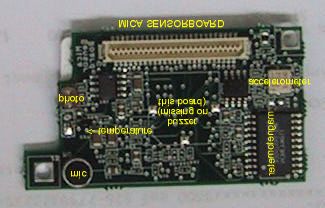
FIGURE 1 The fully-populated Mica Sensorboard (micasb) has five sensors and a single tone buzzer.
Some mica sensorboards do not have all of the possible components. For example, the
board shown above does not have the sounder. If it did, the sounder would be
soldered onto the large square in the middle. Other boards do not have the
magnetomer or accelerometer, but do have the buzzer. The reason for this is cost: and
supply: the magnetometer and accelerometer are relatively expensive, and the buzzer
was in short supply during early 2002.
A predecessor to the micasb was the Basic Sensorboard. The Basic Sensorboard has
only a thermistor and photo cell. While the Basic Sensorboard can run on the Mica
mote, a few precompilation steps must be taken. See DEFAULT SENSORBOARDS for
more information. Alternatively, the micasb is not compatible with mote platforms
other than Mica.
Mica Sensorboard Subcomponents
Below is a table of subcomponents. This information comes from the Bill of Materials
for the micasb which you can find on the TinyOS web site. For the Bill of Materials
spreadsheet and more detailed technical information, please refer to GUIDE TO
ADDITIONAL ONLINE Information.
Description Company Manufacturer
Microphone Panasonic WM-62A
Sounder Sirius PS14T40A
Accelerometer Analog Devices ADXL202JE
2M I C A S E N S O R B O A R D
Thermistor Panasonic ERT-J1VR103J
Light Sensor Clairex CL9P4L
Magnetometer Honeywell HMC1002
All of the sensors are sampled by the Mica's ATmega103 which produces 10-bit
samples. The semantics of the data depend on the specific sensor. For example, 0x80 is
roughly 25 degree celcius for the temperature sensor and varies in a non-linear fashion
similar to the light sensor. The microphone is just an AC signal (or relative signal to
the center line ~= 512) and depends on the GAIN setting (which is set in the
microphone component – see Adjusting the Gain for more information). See
Subcomponent Specifics for more information on how to interpret each sensor’s data.
Programming Practices
Relevant files
Sensorboard.h
Default Sensorboards
Sampling rates
Fffff
Subcomponent Specifics
Magnetometer
Accelermeter
Microphone
Sampling
The microphone offers several output options:
?? sounder tone detected (binary yes or no)
?? voice out (100Hz - 6.5kHz)
?? sounder out (3.5kHz - 4.5kHz)
?? phase output of sounder
If you read from ADC2, a mux determines whether you get the phase output from (1)
the tone detecter (which detects 3.5kHz - 4.5kHz) or (2) either the output from the
3M I C A S E N S O R B O A R D
sounder BP filter or the voice BP filter. The MIC component allows you to choose
between (1) or (2).
Within (2), a resister controls whether the output from the voice BP filter or sounder
BP filter is seen. You change which output you see on ADC2 by resoldering. If you
look on the mica sensorboard schematic (which you can get off the hardware page
easily because the hw page was just reorganized to make finding mica stuff easier) ,
look just above and to the right of the word 'MAGNETOMETER'. You'll see
'mic_bandpass_out' and 'mic_out'. These are labeled as R41 and R42. You'll see that
the resister is currently on R41. You can resolder to put it on R42.
Adjusting the Gain
The microphone gain can be set in one of several ways. The way that the tone_detect
and micasb_test2 apps set it is by wiring a command to the MIC:MIC_POT_ADJUST
command and calling it from the INIT command. Here are the specifics from the
micasb_test2 app:
micasb_test2.c:
char TOS_COMMAND(MICASB_TEST2_INIT)(){
(...unrelated code...)
/* Turn Microphone on and set the pot setting to 64,
use bandpass filter output, no interrupt*/
TOS_CALL_COMMAND(MICASB_TEST2_MIC_INIT)();
TOS_CALL_COMMAND(MICASB_TEST2_MIC_PWR)(1);
TOS_CALL_COMMAND(MICASB_TEST2_MIC_MUX_SEL)(1);
TOS_CALL_COMMAND(MICASB_TEST2_POT_ADJUST)(64);
TOS_CALL_COMMAND(MICASB_TEST2_MIC_TONE_INTR)(0);
(...unrelated code)
}
micasb_test2.desc: MICASB_TEST2:MICASB_TEST2_POT_ADJUST MIC:MIC_POT_ADJUST
Sounder
Thermistor
Blah blah blah.
4M I C A S E N S O R B O A R D
The thermistor and photo cell share the same ADC port due to
Prior to TinyOS
1.0, the
resource limitations. The definitions of the port illustrate the
thermistor and
contention:
the photo sensor
share the same
#define PHOTO_PORT 1 /* TOS_ADC_PORT_1 */
ADC port and #define TEMP_PORT 1 /* TOS_ADC_PORT_2 */
require special
handling. Prior to TinyOS 1.0, you must turn one or the other off and sample
the other. To turn off and on, look at code in tos/system/TEMP.c.
The command TEMP_INIT turns the temp on and TEMP_PWR
turns the pwr off. You can toggle between the two. For the photo sensor, look for the
analagous commands in PHOTO.c.
Photo cell
TinyOS Sensor Components
Sample Code
Guide to Additional Online Information
Datasheets.
Schematic.
BOM.
Sample code.
56
You can also read