MaxxFlow HTC Flow Measurement for Dry Bulk Solids - EN
←
→
Page content transcription
If your browser does not render page correctly, please read the page content below
EN

                      MaxxFlow HTC
                      Flow Measurement
                      for Dry Bulk Solids
Product Information

                                            SWR engineering Messtechnik GmbH
Product Information
Use
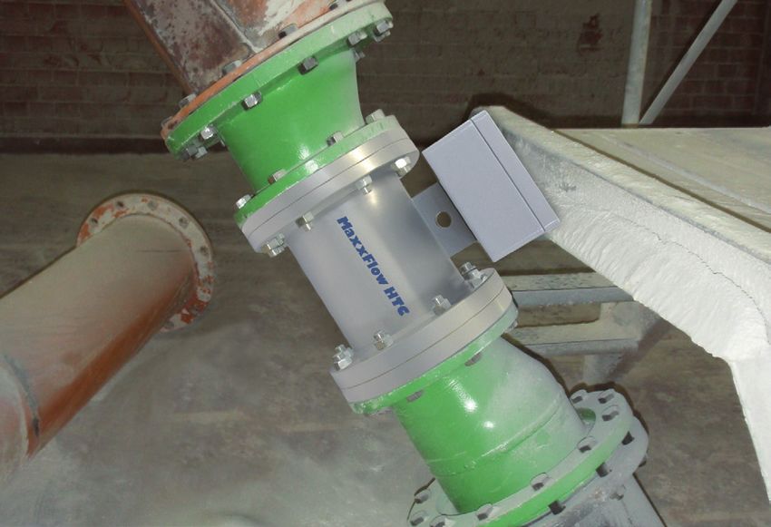
The MaxxFlow HTC is specially developed for the flow
measurement of dry bulk solids during high-volume
throughput. Due to its completely open profile and its low
installation height, the MaxxFlow HTC is especially suitable
in situation in which it was previously only possible to use
complicated or expensive mechanical solutions, e.g. impact
plates or measuring chutes.
The installation of the MaxxFlow HTC takes place
independently of the direction of the line (vertical/inclined),
but always after mechanical conveyor elements, e.g. rotary
conveyors or screw conveyors.
120 t/h 80 t/h
MaxxFlow HTC
MaxxFlow HTC
Screw conveyor
Rotary conveyor
Function
After the conveyor, the material to be measured falls or h = constant v= √2 x g x h
slides through an inlet path and runs through the sensor. v = Speed
MaxxFlow HTC
During the throughput, the MaxxFlow HTC records the g = Gravity acceleration
h = Height of fall
material type and speed. Since the material falls from a
constant height after emerging from the conveyor element,
the speed of the product stream is accelerated, but is
constant at the installation position of the sensor.
Due to this constant speed, the speed measurement
does not need to be activated in every case, but can be
calculated as a constant depending on the height of the
fall. The mass flow is determined as follows:
Ceramic
inner pipe
Q (kg/s) = K (kg/m3) x v (m/s) x A (m2) �
Through the input coupling of a high-frequency, electro-
magnetic alternating field, a homogenous measuring field
is generated in the measuring tube.
The measuring tube (interior tube of the sensor) consists
of wear-resistant Al2O3 ceramics. Dry bulk solids inside the If the material speed varies, for example due to a change in
measuring field reduce the amplitude of the alternating initial speed, then this can also be measured.
field. This takes place through a runtime measurement with
This leads to a measuring signal that is in proportion to the the help of two additional electrodes behind the interior
concentration of the dry bulk solids in the sensor (kg/m3) ceramics tube.
2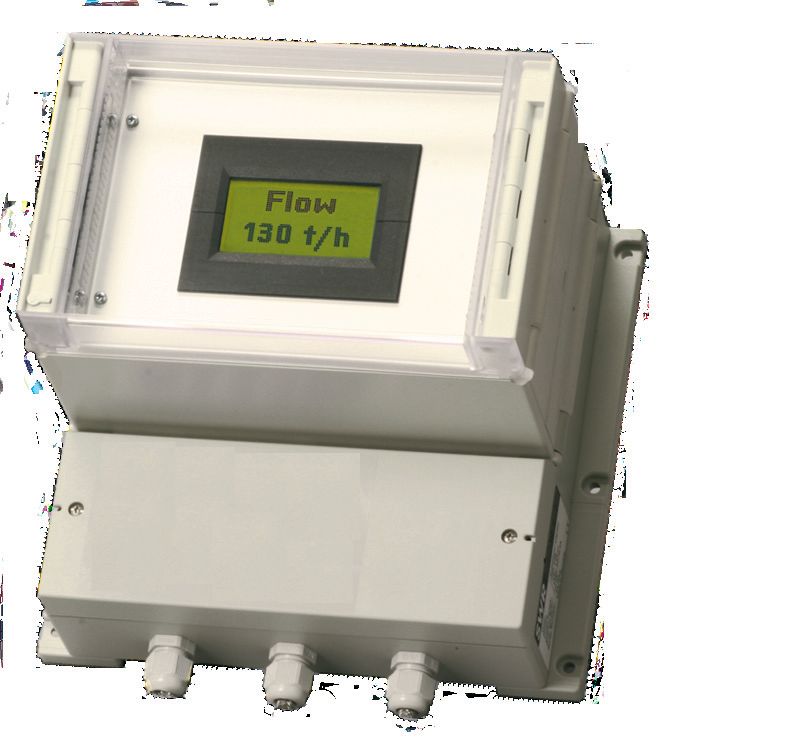
Product Information

Calibration
The recording of the speed is in every case independent
of the type of the dry bulk solids that are to be measured,
since they can either be calculated or based on a runtime
measurement.
Thus the speed measurement requires no calibration.
This makes a new and simple type of calibration possible:
A material sample (approx. 10 Liter = sensor volume) can
be poured into the sensor via a filling nozzle in the inlet
path above the sensor.
There is a knife-gate below the sensor that is closed for
the calibration. If the sensor is completely full, then the
measured density value must correspond to the bulk
density of the material.
This bulk density (set point) can simply be determined
as a gram per liter weight and entered in the evaluation
unit (full calibration). Even with large product flows, the
measurement is completely calibrated with a material
sample of only about 10 liter.
Material drop-tests using calibration points during a
running process are thus a thing of the past.
The handling of several tons of material as a reference
therefore is no longer necessary.

                                                                                Sensor
System
A complete measuring station consists of these
components:                                                        +
                                                              Evaluation unit
• Measuring feeder for installation in the conveyor line
• Evaluation unit MFE 100

The measuring feeder is available in sizes DN 150 mm
and DN 200 mm.
On request the components inlet path (between conveyor
element and sensor) and gate valve (for calibration) can
also be configured and supplied.

The evaluation unit are connected to the sensor using
5-wired, shielded cable.
The maximum distance between measuring feeder and
evaluation unit is 300 m.

                             DN 150 mm   DN 200 mm

3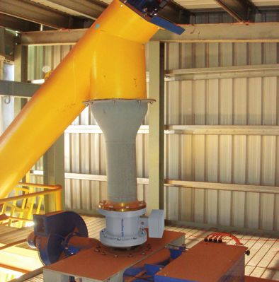
Product Information

Configuration
For the configuration of the sensors, the knowledge of the                           MaxxFlow DN 150 throughput at max. 50 % fill level
                                                                      300.0
maximum volume flow is fundamentally important in order
to configure the measuring point in such a way that the dry           250.0

bulk solids can flow through the sensor unhindered and                200.0

the product flow is not influenced.

                                                               m³/h
                                                                      150.0
The diagrams in figure 1 and 2 show the maximum
conveyable volume depending on material speed for the                 100.0

two sensor sizes DN 150 mm and DN 200 mm.                              50.0

The sensor cross-section in both cases is filled to 50 %.
                                                                        0.0
                                                                              0       0.5   1    1.5   2    2.5   3     3.5   4         4.5       5

                                                                                                            m/s                       Speed of fall

Example:
                                                                  Figure 1
If the max. mass flow amounts to 80 t/h, and if the material
has a bulk density of 0.8 t/m3, then the maximum volume
flow amounts to 100 m3/h.
When using a MaxxFlow HTC DN 150 mm, a speed of
approx. 3 m/s would be necessary.
                                                                                     MaxxFlow DN 200 throughput at max. 50 % fill level
When using a MaxxFlow HTC DN 200 mm, a speed of                       300.0
approx. 1.7 m/s will be required.
                                                                      250.0
Figure 3 shows that for these speeds to be reached, an inlet
path of 0.5 respectively 0.15 m will be necessary between             200.0

the conveyor and the sensor.
                                                               m³/h

                                                                      150.0

                                                                      100.0

                                                                       50.0

Turndown and measuring range                                            0.0
                                                                              0       0.5   1    1.5   2    2.5   3    3.5    4        4.5       5

Which sensor type is being used depends on the available                                                   m/s                        Speed of fall

standing installation height and the turndown or the
desired measuring range.                                         Figure 2
The sensor itself has an installation height of 290 mm
(DN 150 mm) or 310 mm (DN 200 mm).
To equip the measuring point from the above example with
a DN 150 mm sensor, an installation height of
500 mm + 290 mm = 790 mm would be necessary.                            Inlet path
The turndown, i.e. the ratio between the end and the                   1.2
beginning of the measuring range, amounts to 1:5 for all
                                                                       1.0
MaxxFlow HTC sensors.
With regard to the example provided, it is possible to                 0.8

measure with a MaxxFlow HTC DN 150 mm between                   m
                                                                       0.6
                                                                m

20 m3/h and 100 m3/h.
                                                                       0.4

                                                                       0.2

                                                                         0
                                                                              0      0.5    1    1.5   2    2.5   3     3.5       4      4.5          5
                                                                                                            m/s                        Speed of fall

                                                                 Figure 3

4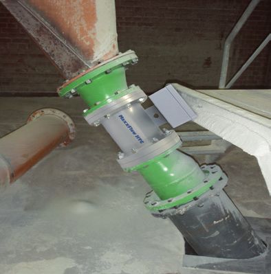
Product Information

A MaxxFlow HTC DN 200 mm can also be used for this
measuring task. Care must be taken that the angle for                                                             �

the contractions of the inlet path at a height of 0.15 m
does not become too flat. The angle α (see figure 4) must
be at least 60° in order to guarantee a flawless product
                                                                                                                  Inlet path
flow. If the inlet path (height of fall) must be enlarged to
maintain the demand after an angle > 60°, then it must
be noted that the lower limit of the measuring range                                α ≥ 60°
                                                                                           α
moves upward.
                                                                                                                  �
If for example an inlet path of 0.3 m would become
necessary, then the speed would be approx. 2.5 m/s
and thus the maximum volume for a MaxxFlow HTC
DN 200 mm 150 m3/h.
With a turndown of 1:5, the lower measuring range limit           Figure 4
would then be 30 m3/h.

Advantages
• installation free of obstacles in the cross-section,           • zero-contact measuring procedure
  therefore no dead spots                                          (no mechanics)
• independent of the arragement of the line                      • maximum material temperature 120 °C
  (vertical or inclined)
                                                                 • pressure-resistant up to 10 bar on request
• simple refitting
                                                                 • abrasion-resistant ceramic inner pipe
• dust proof

Dimensions
                                                         268,7

                                                                                                                                294

    36                                                            23,5

                                  8                                                                8
                                      xØ                                                             xØ
                                                                                                                      10

                                Ø    22                                                          Ø      22                 M8
                                   1
                              Ø 2 50                                                            Ø 340
                                  40                                                             29
                             Ø2                                                                Ø2 5
                                85                                                               00

                             Flange EN 1092-1
                             01 A / DN 150 /                                                   Flange EN 1092-1
               290           PN 10 / 150                                                       01 A / DN 200 /
                                                                              310              PN 10 / 200

5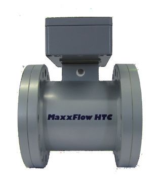
Product Information

Technische Daten

 Sensor                                                                 Evaluation unit

                                    Steel St52, powder-coated           Power supply               110 / 240 V AC, 50 Hz, optional 24 V DC
                                    (optional stainless steel 1.4541)
 Housing                                                                Power consumption          20 W / 24 VA
                                    NW 150/200 mm,
                                    Flange according EN 1092-1          Protection category        IP 65 to EN 60 529/10.91
 Inner pipe                         Ceramic Al2O3                       Operating temperature      -10 … +45 °C [14 … 113 °F]
 Protection category                IP 65; ATEX: Cat. 3 D               Dimensions                 225 x 237 x 174 (W x H x D)
                                    Sensor pipe:      -20 … +120 °C     Weight                     Approx. 2.5 kg
 Operating temperature
                                    Sensor electronic: 0 … + 60 °C
                                                                        Cable glands               3 x M16 (4.5-10 mm Ø)
 Max. working pressure              1 bar, optional 10 bar
                                                                        Terminal clamp wire size   0.2-2.5 mm2 [AWG 24-14]
 Working frequency                  88 kHz
                                                                                                   2 x 4 … 20 mA (0 …20 mA),
 Transmitting power                 Max. 2 mW                           Current output signal
                                                                                                   load < 700 Ω
 Weight                             Depending to model                  Alarm output
                                                                                                   Relay with toggle switch -
                                    NW 150: B = 420 mm, H = 290 mm                                 max. 250 V AC, 1 A
 Dimensions                                                             Error output
                                    NW 200: B = 480 mm, H = 310 mm
                                    ± 2 …5 %                            Data backup                Flash memory
 Accuracy
                                    (in calibrated measuring range)
                                                                        Impulse output             Open collector - max. 30 V, 20 mA

                                                                        RS 485 interface           ModBus

                                                                                                                                              (All rights reserved.)

                       SWR engineering Messtechnik GmbH
                       Gutedelstraße 31 · 79418 Schliengen (Germany)
                       Fon +49 7635 82 72 48-0 · Fax +49 7635 82 72 48-48 · www.swr-engineering.com

6		                                                                                                                             EN 25/11/11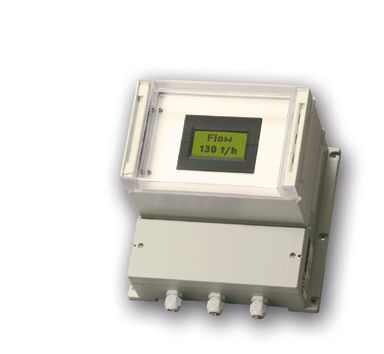
You can also read