Installations Vessels with Fuel Cell Power Guidelines on - IRS-G-SAF-05 Indian Register of Shipping
←
→
Page content transcription
If your browser does not render page correctly, please read the page content below
Guidelines on
Vessels with Fuel Cell Power
Installations
(Provisional)

September 2021

Indian Register of Shipping   IRS-G-SAF-05   Page | 1

Guidelines on Vessels with Fuel Cell Power Installations
2021
Guidelines on
Vessels with Fuel Cell Power Installations
(Provisional)
September 2021
Contents
Sections
Introduction
1 General
1.1 Application
1.2 Goal
1.3 Functional requirements
1.4 Definitions
1.5 Alternative design
1.6 Risk Assessment
1.7 Fuel Cell Certification
1.8 Plans and Documentation
1.9 Operation Manual
2 Design Principles for Fuel Cell Power Installations
2.1 Fuel cell spaces
2.2 Arrangement and access
2.3 Atmospheric control of fuel cell spaces
2.4 Materials
2.5 Piping arrangements
2.6 Exhaust gas and exhaust air
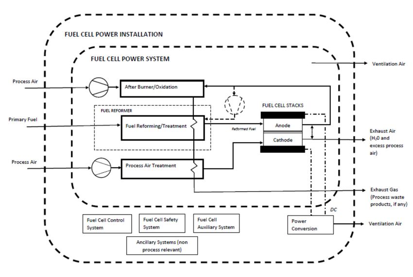
2.7 Fuel Cell Modules
2.8 Fuel Cell Power Systems
2.9 Fuel Preparation Rooms and Pumps
2.10 Fuel Tanks and Fuel Containment Systems
2.11 Fuel Supply System to Consumers
2.12 Air Locks
2.13 Bunkering Arrangements
Indian Register of Shipping IRS-G-SAF-05 Page | 2Guidelines on Vessels with Fuel Cell Power Installations
2021
3 Fire Safety
3.1 General
3.2 Structural Fire Protection
3.3 Fire Detection
3.4 Fire and explosion protection
3.5 Fire Extinguishing
3.6 Fire dampers
3.7 Personnel Protective Equipment for use of Hydrogen as fuel
4 Electrical Installations
4.1 General
4.2 Area classification
4.3 Certified safe Equipment
4.4 Emergency Shutdown
5 Control, Monitoring and Safety Systems
5.1 General
5.2 Gas or Vapour Detection
5.3 Liquid Detection
5.4 Ventilation Performance
5.5 Bilge Wells
5.6 Bunkering and Fuel Tank Monitoring
5.7 Fuel Pump Monitoring
5.8 Fuel Cell Condition Monitoring
5.9 Fuel supply remote emergency stop
5.10 Emergency shutdown push buttons
5.11 Actions of the alarm system and safety system
6 Inspection and Maintenance
6.1 General
6.2 Inspection and Maintenance Manual
6.3 Personnel Qualification
7 Surveys
7.1 General
7.2 Surveys during Construction
7.3 Periodical Surveys
Indian Register of Shipping IRS-G-SAF-05 Page | 3Guidelines on Vessels with Fuel Cell Power Installations
2021
Appendices
Appendix A – Fuel Cell Technologies
Appendix B - Risks associated with Hydrogen as fuel in fuel cells and possible mitigation
measures
References
Indian Register of Shipping IRS-G-SAF-05 Page | 4Guidelines on Vessels with Fuel Cell Power Installations
2021
Introduction
A fuel cell is a device that continuously converts an oxidizing fuel (hydrogen, methanol etc.) into electricity
and water through an electrochemical reaction. The main distinction among fuel cell types is the electrolyte,
and hence they are classified by the electrolyte (See Appendix A for a brief description of fuel cells). Fuel
cells are different from batteries in that a battery stores energy, while a fuel cell generates energy by
converting fuel. As long as there is fuel, the fuel cell continues to convert the energy into power.
Vessel power systems are typically comprised of redundant systems. This enables optimizing fuel
consumption to the load demand and offers resilience in case of failure of a power system. Fuel cells nicely
fit this requirement, as they may be combined into “modules”, and those modules can be operated efficiently
and combined to meet the overall power requirement. Selection of the fuel cell stack and module designs
(power, voltage, etc.) will depend on the target applications (e.g., power for emergency, or auxiliary, or
propulsion, etc.)
These guidelines have been developed to provide requirements for vessels with fuel cell power installations.
These guidelines provide requirements for the design, construction, testing and surveys of vessels
equipped with fuel cells.
The goal of these guidelines is to provide criteria for the arrangement and installation of fuel cell power
installations with at least the same level of safety as new and comparable conventional oil-fuelled main and
auxiliary machinery installations, regardless of the specific fuel cell type and fuel. Depending on the fuel
used, other regulations (Part 5, Chapter 35 of IRS Rules and Regulations for the Construction and
Classification of Steel Ships) and provisions (e.g. IRS Guidelines for Natural Gas fueled vessels for Coastal
and Inland Waters, Guidelines on Methanol fueled vessels) would be applicable in addition to these
guidelines.
These guidelines are to be used in conjunction with the applicable Rules of IRS for construction and
classification of vessels.
Vessels provided with fuel cell installations for propulsive power and auxiliary purposes in accordance with
these guidelines may be assigned additional class notation FC (Main) and FC (Auxiliary) respectively. A
qualifier indicating the particular low flashpoint fuel (methanol, ethanol, propane, butane, hydrogen) used
in the fuel cell will be added to the notation, e.g: FC (Main) – Hydrogen.
There may be cases where vessels are used in fuel cell-battery hybrid configurations. In such cases, the
requirements of IRS Guidelines on Battery Powered Vessels and Classification Note: Approval of Lithium-
ion Battery Systems, are also to be applied, as relevant and applicable.
In general, the recommendations/ requirements in these guidelines are applicable to all types of fuel cell
configurations and fuels. Specific recommendations/ requirements (as indicated in this document) may be
taken cognisance of, for particular fuels/ fuel cell configurations.
Indian Register of Shipping IRS-G-SAF-05 Page | 5Guidelines on Vessels with Fuel Cell Power Installations
2021
Section 1
General
1.1 Application
1.1.1 These guidelines are applicable to vessels fitted with fuel cell power installations which are fuelled by
low flashpoint fuels.
1.2 Goal
1.2.1 These guidelines are intended to provide safe and reliable delivery of electrical and/or thermal energy
through the use of fuel cell technology.
1.3 Functional requirements
These guidelines are related to the goals and functional requirements of the IGF Code and the risk
assessment approach. In particular, the following apply:
1.3.1 The safety, reliability and dependability of the systems is to be equivalent to that achieved with new
and comparable conventional oil-fuelled main and auxiliary machinery installations, regardless of the
specific fuel cell type and fuel.
1.3.2 The probability and consequences of fuel-related hazards is to be limited to a minimum through
arrangement and system design, such as ventilation, detection and safety actions. In the event of gas/ liquid
leakage or failure of the risk reducing measures, necessary safety actions are to be initiated.
1.3.3 The design philosophy is to ensure that risk reducing measures and safety actions for the fuel cell
power installation do not lead to an unacceptable loss of power.
1.3.4 Hazardous areas are to be restricted, as far as practicable, to minimize the potential risks that might
affect the safety of the vessel, persons on board and equipment.
1.3.5 Equipment installed in hazardous areas are to be minimized to that required for operational purposes
and are to be suitably and appropriately certified.
1.3.6 Fuel cell spaces are to be configured to prevent any unintended accumulation of explosive, flammable
or toxic gas concentrations.
1.3.7 System components are to be protected against external damages.
1.3.8 Sources of ignition in hazardous areas are to be minimized to reduce the probability of fire/ explosions.
1.3.9 Piping systems and overpressure relief arrangements that are of suitable design, construction and
installation for their intended application are to be provided.
1.3.10 Machinery, systems and components are to be designed, constructed, installed, operated,
maintained and protected to ensure safe and reliable operation.
1.3.11 Fuel cell spaces are to be arranged and located such that a fire or explosion will not lead to an
unacceptable loss of power or render equipment in other compartments inoperable.
Indian Register of Shipping IRS-G-SAF-05 Page | 6Guidelines on Vessels with Fuel Cell Power Installations
2021
1.3.12 Suitable control, alarm, monitoring and shutdown systems are to be provided to ensure safe and
reliable operation.
1.3.13 Fixed leakage detection suitable for all spaces and areas concerned are to be arranged.
1.3.14 Fire detection, protection and extinction measures appropriate to the hazards concerned are to be
provided.
1.3.15 Commissioning, trials and maintenance of fuel systems and gas utilization machinery are to satisfy
the goal in terms of safety, availability and reliability.
1.3.16 The technical documentation is to permit an assessment of the compliance of the system and its
components with the applicable rules, guidelines, design standards used and the principles related to
safety, availability, maintainability and reliability.
1.3.17 A single failure in a technical system or component is not to lead to an unsafe or unreliable situation.
1.3.18 Safe access is to be provided for operation, inspection and maintenance.
1.4 Definitions
For the purpose of these guidelines, the terms used have the meanings defined in the following paragraphs.
Terms not defined have the same meaning as in SOLAS chapter II-2 and the IGF Code.
1.4.1 Fuel cell is a source of electrical power in which the chemical energy of a fuel cell fuel is converted
directly into electrical and thermal energy by electrochemical oxidation.
1.4.2 Fuel reformer is the arrangement of all related fuel-reforming equipment for processing gaseous or
liquid primary fuels to reformed fuel for use in the fuel cells.
1.4.3 Fuel cell stack is an assembly of cells, separators, cooling plates, manifolds and a supporting structure
that electrochemically converts, typically, hydrogen rich gas and air reactants to DC power, heat and other
reaction products.
1.4.4 Fuel cell module is an assembly incorporating one or more fuel cell stacks and other main and, if
applicable, additional components, which is intended to be integrated into a power system.
1.4.5 Fuel cell power system is the group of components which may contain fuel or hazardous vapours,
fuel cell(s), fuel reformers, if fitted, and associated piping systems.
1.4.6 Fuel cell power installation is the fuel cell power system and other components and systems required
to supply electrical power to the vessel. It may also include ancillary systems for the fuel cell operation.
1.4.7 Fuel preparation space is any space or room containing equipment for fuel preparation purposes,
such as fuel pumps, fuel valve train, heat exchangers and filters.
1.4.8 Fuel cell space is a space or enclosure containing fuel cell power systems or parts of fuel cell power
systems.
1.4.9 Exhaust gas is exhaust from the reformer or anode side of the fuel cell.
1.4.10 Exhaust air is exhaust from the cathode side of the fuel cell.
1.4.11 Primary Fuel is fuel supplied to the fuel cell power system.
Indian Register of Shipping IRS-G-SAF-05 Page | 7Guidelines on Vessels with Fuel Cell Power Installations
2021
1.4.12 Reformed fuel is hydrogen rich gas generated in the fuel reformer.
1.5 Alternative designs
1.5.1 These guidelines contain functional requirements for all appliances and arrangements related to the
usage of fuel cell technology.
1.5.2 Appliances and arrangements of fuel cell power systems may deviate from those set out in these
guidelines, provided such appliances and arrangements meet the intent of the goal and functional
requirements concerned and provide an equivalent level of safety of the relevant sections.
1.5.3 The equivalence of the alternative design is to be demonstrated as specified in SOLAS Regulation II-
1/55 and approved by the Administration. However, operational methods or procedures to be applied; as
an alternative to a particular fitting, material, appliance, apparatus, item of equipment or type thereof which
is prescribed by these guidelines; will not be permissible.
1.5.4 IRS Guidelines on Alternative and Risk Based Design Evaluation may also be referred.
1.6 Risk Assessment
1.6.1 A risk assessment is to be conducted to identify risks arising from the use of fuels (methyl/ethyl
alcohol, hydrogen, etc.) affecting the structural strength or the integrity of the vessel, safety of crew on
board, and preservation of the environment. Consideration is to be given to the hazards associated with
physical layout, operation and maintenance following any reasonably foreseeable failure. The risks are to
be analyzed using acceptable and recognized risk analysis techniques. Loss of function, component
damage, fire, explosion and electric shock are to be considered as a minimum. The analysis should identify
risks that can be eliminated wherever possible. Risks which cannot be eliminated are to be mitigated as
necessary. Identification of risks, and the means by which they are mitigated, are to be documented to the
satisfaction of IRS and to the flag Administration if required. Risk assessment may be carried out in
accordance with recognised standards such as ISO 31010:2009.
1.6.2 A risk analysis of the fuel cell installation systems is to be performed to assess the consequences of
a failure affecting the systems and/or a gas leakage. The required analysis can be a FTA, FMEA, HAZOP
analysis, a combination of techniques or another type of analysis.
Note: The following points need to be considered:
• The risk analysis should be based on the single failure concept, which means that only one failure
needs to be considered at a time.
• Both detectable and non-detectable failures.
• Consequences failures, i.e. failures of any component directly caused by a single failure of another
component.
1.6.3 The scope of the risk analysis should be as follows:
(i) Identify all the possible failures in the concerned systems which could lead to a loss of the
designated/required function;
(ii) Evaluate the consequences;
(iii) Identify the method of failure detection;
(iv) Identify the corrective measures in the system design and operations
a. such as redundancies or safety devices, monitoring or alarm provisions which permit
restricted operation of the system;
b. such as initiation of the redundancy or activation of an alternative mode of operation.
Indian Register of Shipping IRS-G-SAF-05 Page | 8Guidelines on Vessels with Fuel Cell Power Installations
2021
1.6.4 The fuel cell power system risk assessment report is to be submitted for review, and as a minimum
is to address the following issues, as relevant and applicable:
o High energy collision with potential to penetrate a Liquid Hydrogen tank
o Rupture of compressed hydrogen/ liquefied hydrogen tank containment system
o Leakage of hydrogen gases, any fuels gases
o Internal leakage in fuel cell module
o Issues associated with storage of hydrogen as fuel, such as vicinity of other equipment,
corrosion, extreme high temperature, etc.
o Exothermic reaction of reformer material
o Failure of fuel pressure reduction
o Failure of the electrical power output conditioning system
o Thermal runaway of onboard energy buffer
o Loss of inert gas system
o Toxicity potential and risk of oxygen deficiency or other negative impacts on crew health
due to fuels and inert gases
o Safe handling, stowage, marking and carriage of flammable, toxic, and other dangerous
substances
o Sufficient capacity of each drip tray to provide that the maximum amount of spill can be
handled
o Special consideration of closed or semi-enclosed bunkering station with mechanical
ventilation;
o Likely causes and consequences of release of fuel. The consequences of any release of
fuel are to be minimized, while providing safe access for operation and inspection
o Safe handling and containment arrangement for excess fuel (e.g. in the fuel cell stack)
where there is no recirculation to the fuel processing system
o Risk of electrical shock (touching of fuel cell plates)
o Permanently installed gas detectors at ventilation inlets to accommodation and machinery
spaces
o Arrangement of any fixed and/or portable fire extinguishing systems
o Gas detection systems
o Control, monitoring and safety systems
o Black-out
o Arrangement and the number of personnel protective equipment (i.e., eyewash, safety
shower, safety glasses, canister mask, etc.)
o Risks associated with gases “heavier than air” (eg: propane, butane or other gases)
1.6.5 As a guidance, risks associated with using hydrogen as a fuel in fuel cells and possible mitigation
measures are indicated in Appendix B.
1.7 Fuel Cell Certification
1.7.1 Fuel cell power systems are to be certified at the manufacturer’s facility. The Table below provides
certification requirements for certain equipment and components of the fuel cell system.
Indian Register of Shipping IRS-G-SAF-05 Page | 9Guidelines on Vessels with Fuel Cell Power Installations
2021
Table 1.7.1 : Certification Requirements – Fuel Cells
Equipment/ Component Product Certification Requirements/ Standards
Fuel Cell Modules Required IEC 62282-2-100:2020
Fuel cell power system Required IEC 62282-3 series
Pt 4, Ch 5 of IRS Rules (Main
Pressure Vessels Required
Rules)
Pt 5, Ch 4 of IRS Rules (Main
Pipes, Valves and Fittings Required
Rules)
Pt 4, Ch 5 & Pt.5, Ch. 4 of IRS
Hydrogen Storage Tank Required
Rules (Main Rules)
Fuel Cell Control and
Required IEC 62282-3 series
Monitoring System
Electrical Equipment Required Pt 4, Ch 8 of IRS Main Rules
Recognised national/
Gas detection system Required
international standards
Fire detection and alarm
Required FSS Code
system
Fire extinguishing system Required FSS Code
Recognised national/
Bunker Hoses1 Required
international standards
Note:
1. Where used, bunker hose assemblies are to be burst tested to an international standard to
demonstrate they are able to withstand a pressure not less than five (5) times its design pressure without
indication of failure or leakage subject to the satisfaction of the attending Surveyor.
1.8 Plans and Documentation
1.8.1 In general, following is the list of plans and documentation to be submitted to IRS for review. There
could be some differences depending upon the type of fuel, fuel cell chemistry, etc.:
(i) Description of the process and function of the fuel cell system, including fuel cell design and
capacity calculations
(ii) Piping and instrumentation diagrams, with block circuit diagrams of the overall system,
including parts lists or equipment lists
(iii) Technical documents of the components, including the fuel cell stacks themselves
(descriptions, specifications, verification of suitability according to existing standards and rules,
approvals and inspection certificates)
(iv) General arrangement of the machinery spaces containing the gas utilization equipment and of
the gas storage units, with description of the classification of hazardous areas
(v) Risk analysis (FTA, FMEA, HAZOP analysis, or another type of analysis). The document is to
identify and evaluate the hazards associated with each function of the fuel cell power system
throughout its lifecycle. The risk assessment is to also include the necessary parameters for
the safe and effective operation of the control, monitoring and safety systems. The risk
assessment is also to take into account aspects indicated at 1.6.4, 2.8.1, 2.10.1, 2.11.3, 3.5.2,
4.2.4, 4.2.5, 4.4.2, 5.2.1, 5.8.3, 5.11.3 and 5.11.7.
Indian Register of Shipping IRS-G-SAF-05 Page | 10Guidelines on Vessels with Fuel Cell Power Installations
2021
(vi) Control, monitoring and safety systems
(vii) Fire detection and extinguishing systems
(viii) Single line diagram for Fuel cell power system
(ix) Emergency shutdown arrangements (for bunkering system, fuel supply system,
disconnection arrangements, etc.)
(x) Hazardous area classification plan
(xi) List of all electrical equipment installed in the hazardous areas.
(xii) Design data, piping and instrumentation diagram and sizing calculation of the liquid/ gas
storage and piping systems
(xiii) Fuel properties (storage pressure, temperature, LFL, toxicity, corrosivity and any other
important safety related characteristics)
(xiv) Operation and maintenance manual of the fuel cell installation (refer Cl. 1.9)
(xv) Fuel bunkering station arrangements
(xvi) Fuel cell physical environment and operating conditions including the following:
a. Electrical power input, output
b. Fuel input: type, volume, rate, temperature, supply pressure
c. Water input (when required for the operation): quantity, temperature, supply pressure
d. Vibration, shock and bump limits
e. Guideline for handling, transportation, and storage
f. System purging
g. Fuel characteristics (storage pressure, temperature, LFL, toxicity, corrosivity and any
other important safety related characteristics)
(xvii) Maintenance schedule and procedures for fuel cell replacement
(xviii) General arrangement of the fuel containment system
(xix) Fuel containment system structure (including the installation of supports)
(xx) Loading and unloading systems, venting systems, and gas-freeing systems, as well as a
schematic diagram of the remote controlled valve system
(xxi) Technical fire protection file (refer Cl. 3.4.4)
(xxii) Ventilation system
(xxiii) Testing/Trials Plan: The test plan is to identify all equipment, fuel cell power systems and the
recommended method of performing the tests or trials.
Indian Register of Shipping IRS-G-SAF-05 Page | 11Guidelines on Vessels with Fuel Cell Power Installations
2021
1.9 Operation and Maintenance Manual
1.9.1 An operation and maintenance manual detailing procedures for set-up and use of the fuel cell power
system is to be provided. Particular emphasis is to be given to safety measures and any anticipated
improper methods of operation.
1.9.2 In case of programmable fuel cell systems, detailed information on methods of programming,
equipment required, program verification and additional safety procedures (where required) are to be
provided.
1.9.3 The manual is to include, but not be limited to the operational procedures for the loading, storage,
operation, maintenance, and inspection of systems for gas or liquid fuels to minimize the risk to personnel,
together with details of required personal protective equipment and the occupational health hazards
relevant to the use of gas as a fuel.
1.9.4 The manual is to clearly indicate and/or include, but is not to be limited to, the following:
● Start-up and operational procedure
● Fuel cell module specification and general characteristics
● Sequence of operation(s)
● Frequency of inspection
● Normal and emergency shut-down procedures
● Storage procedure and conditioning
● Bunkering procedure
● Maintenance and repair procedures
● Functional testing plan for automation and control system
● Maintenance and function testing plan details of all components and instrumentations
● General notes and prohibited operation; information on the physical environment (for example,
range of ambient temperatures for operation, vibration, noise levels, atmospheric contaminants)
where appropriate
● Procedures for making areas safe for hot work on or near fuel systems
● Installation procedure (including handling, transportation, preparation, fixing method of the
module, connection method of gas and coolant piping, connection method of the electric line and
sensors and circuit diagram(s))
● Bunkering procedure including the maximum transfer rate at all stages and volume to be
transferred
● Pre-bunkering operations/verification all necessary requirements and documented in the bunker
safety checklist
● Communication devices used in bunkering
Indian Register of Shipping IRS-G-SAF-05 Page | 12Guidelines on Vessels with Fuel Cell Power Installations
2021
Section 2
Design Principles for Fuel Cell Power Installations
2.1 Fuel cell spaces
2.1.1 Fuel cell space concept
2.1.1.1 In order to minimize the probability of a gas explosion in a fuel cell space, it is to meet the
requirements of this section, or an equivalent safety concept.
2.1.1.2 The fuel cell space concept is such that the space is designed to mitigate hazards to non-hazardous
levels under normal conditions, but under certain abnormal conditions may have the potential to become
hazardous.
2.1.1.3 Fuel cell spaces (area classification according to Cl. 4.2.2) are considered as hazardous zone 1
and all electrical equipment are to be certified for zone 1.
2.1.1.4 In specific cases where IRS/ the Administration considers the prescriptive area classification to be
inappropriate, area classification according to IEC 60079-10:2020 is to be applied according to Cl. 4.2.1,
taking into account the following guidance: All electrical equipment needs to comply with the resulting area
classification.
2.1.1.5 In specific cases where IRS/ the Administration accepts inerting according to Cl. 2.3.3, as ignition
hazards are mitigated by inerting, there is no need for an immediate (emergency) shutdown of the fuel
supply in case of leakage detection. In case of leakage detection, automatic changeover to other power
supply systems is to take place and a controlled shutdown of the fuel cell and the affected fuel supply
system is to be initiated in order thereby avoiding damage to the fuel cell power system.
2.1.2 The design of fuel cell power systems is to comply with recognised industry standards, such as IEC
62282-2:-100:2020, IEC 62282-3-100:2019.
2.2 Arrangement and access
2.2.1 Fuel cell power installations are to be designed for automatic operation and equipped with all the
monitoring and control facilities required for safe operation of the system.
2.2.2 It is to be possible to shut down the fuel cell power system from an easily accessible location
outside the fuel cell spaces.
2.2.3 Means to safely remove the primary and reformed fuel from the fuel cell power system are to be
provided.
2.2.4 Means are to be provided to set a fuel cell power installation into a safe state for maintenance and
shutdown.
2.2.5 For the auxiliary systems of the fuel cell power system where primary fuel or reformed fuel may leak
directly into a system medium (e.g. cooling water), such auxiliary systems are to be equipped with
appropriate extraction and detection means fitted as close as possible after the media outlet from the
Indian Register of Shipping IRS-G-SAF-05 Page | 13Guidelines on Vessels with Fuel Cell Power Installations
2021
system in order to prevent gas dispersion. Gas extracted from the auxiliary system media are to be vented
to a safe location on the open deck.
2.2.6 The reforming equipment, if fitted, may be an integrated part of the fuel cell or arranged as an
independent unit with reformed fuel piping connected to the fuel cell(s).
2.2.7 Fuel cell spaces boundaries are to be gastight towards other enclosed spaces in the vessel.
2.2.8 Fuel cell spaces are to be arranged outside of accommodation spaces, service spaces, machinery
spaces of category A and control stations.
2.2.9 Fuel cell spaces are to be designed to safely contain fuel leakages and be provided with suitable
leakage detection systems.
2.2.10 Fuel cell spaces are to be arranged to avoid the accumulation of hydrogen-rich gas by having simple
geometrical shape and no obstructing structures in the upper part.
2.2.11 Fuel cell spaces containing fuel reformers are also to comply with the requirements relevant for the
primary fuel.
2.2.12 Where an independent and direct access to the fuel cell spaces from the open deck cannot be
arranged, access to fuel cell spaces is to be through an air lock.
2.2.13 An air lock is not required if appropriate technical provisions are made such that access to the space
is not required and not made possible before the equipment inside is safely shut down, isolated from the
fuel system, drained of leakages and the inside atmosphere is confirmed gas-free.
2.2.14 These provisions include but are not limited to:
.1 all controls required for safe operation and gas freeing of the equipment and space are to be
provided for remote operation from outside the space;
.2 all parameters required for safe operation and gas freeing are to be remotely monitored and
alarms are to be given;
.3 the space openings are to be equipped with an interlock preventing operation with the space
open;
.4 the spaces are to be provided with suitable fuel leakage collection and draining arrangements
for remote operation from outside the space; and
.5 provisions are to be made that the fuel equipment inside can be isolated from the fuel system,
drained of fuel and purged safely for maintenance.
2.3 Atmospheric control of fuel cell spaces
2.3.1 General
2.3.1.1 Protection of fuel cell spaces by an external boundary that encloses components where fuel is fed
can be achieved by ventilation or inerting. These methods are to be equally acceptable to ensure the safety
of the space.
2.3.2 Ventilation of fuel cell spaces
2.3.2.1 Fuel cell spaces are to be equipped with an effective mechanical ventilation system to maintain
under pressure of the complete space, taking into consideration the density of potentially leaking fuel gases.
2.3.2.2 For fuel cell spaces on open decks, overpressure ventilation may be considered.
Indian Register of Shipping IRS-G-SAF-05 Page | 14Guidelines on Vessels with Fuel Cell Power Installations
2021
2.3.2.3 The ventilation rate in fuel cell spaces is to be sufficient to dilute the average gas/ vapour
concentration below 25% of the flammable range in all maximum probable leakage scenarios due to
technical failures.
2.3.2.4 Any ducting used for the ventilation of fuel cell spaces is not to serve any other space.
2.3.2.5 Ventilation ducts from spaces containing reformed fuel piping or release sources are to be designed
and arranged such that any possibility for gas to accumulate is avoided.
2.3.2.6 Two or more fans are to be installed for the ventilation of the fuel cell space providing 100%
redundancy upon loss of one fan. 100% ventilation capacity is also to be supplied from the emergency
source of power.
2.3.2.7 In case of failure of one fan, automatic change-over to another fan is to be provided and indicated
by an alarm.
2.3.2.8 In case of loss of ventilation or loss of negative pressure in the fuel cell space the fuel cell power
system is to carry out an automatic, controlled shutdown of the fuel cell and isolation of the fuel supply.
2.3.2.9 Ventilation air inlets for fuel cell spaces are to be taken from areas which, in the absence of the
considered inlet, would be non-hazardous.
2.3.2.10 Ventilation air inlets for non-hazardous enclosed spaces are to be taken from non-hazardous areas
located at least 1.5 m away from the boundaries of any hazardous area.
2.3.2.11 Ventilation air outlets from fuel cell spaces are to be located in an open area which, in the absence
of the considered outlet, would be of the same or lesser hazard than the ventilated space.
2.3.2.12 In general, the requirements of Part 5, Chapter 4, Section 12 of the IRS Rules and Regulations for
the Construction and Classification of Steel Ships are to be complied with, for design of ventilation fans that
serve spaces where vapours may be present.
2.3.3 Inerting of fuel cell spaces
2.3.3.1 Inerting should be accepted for atmospheric control of the fuel cell spaces provided:
.1 protection by inerting is only acceptable where a fuel cell space is not possible to be entered
during inerting and sealing arrangements are to ensure that leakages of inert gas to adjacent
spaces are prevented;
.2 the inerting system complies with Part 6, Chapter 8, Section 15 and Part 5 Chapter 4, Section 6,
Cl. 6.13 and 6.14 of IRS Rules and Regulations for the Construction and Classification of Steel
Ships;
.3 the pressure of inerting media is always to be kept positive and monitored;
.4 any change in the pressure, indicating a breach of the external outer boundary of fuel cell space,
or a breach of the boundary with a space where fuel is flowing (e.g. fuel cell stack, reformer, etc.)
is to activate a controlled shut-off of the fuel supply;
.5 fuel cell space is to be equipped with a mechanical ventilation to evacuate the inerting agent,
after an inerting release has been initiated;
Indian Register of Shipping IRS-G-SAF-05 Page | 15Guidelines on Vessels with Fuel Cell Power Installations
2021
.6 access to the inerted fuel cell space is to be only possible when the space is completely ventilated
by fresh air and the fuel supply is interrupted and depressurized or purged; and
.7 the inerting system is not to be operable under ongoing maintenance or inspection.
2.4 Materials
2.4.1 The materials within the fuel cell power installation are to be suitable for the intended application and
are to comply with recognized standards.
2.4.2 The use of combustible materials within the fuel cell power system is to be kept to a minimum.
2.4.3 In general, materials used in gas tanks, gas piping, process pressure vessels and other components
in contact with cryogenic liquids or gases are to be in accordance with Part 5 Chapter 4, Section 6 of the
IRS Rules and Regulations for the Construction and Classification of Steel Ships.
2.4.4 Materials used in all components in contact with hydrogen are to be resistant to hydrogen
embrittlement, hydrogen attack, hydriding, porosity, permeation and diffusion. A material is not to be used
unless data is available showing that it is suitable for the planned service conditions. In case of any doubt
the material can be subjected to hydrogen embrittlement susceptibility testing (in accordance with ISO
11114-4) to evaluate material suitability before use.
2.4.5 Guidance on suitability of certain materials for hydrogen service is as follows:
Table 2.4: Suitability of certain materials in hydrogen service
Materials Gaseous H2 service Liquid H2 service Remarks
Metals
Aluminium and alloys Yes Yes
Negligibly susceptible
Copper and its alloys (such
to hydrogen
as brass, bronze and Cu- Yes Yes
embrittlement
Ni)
Iron (cast, grey, ductile) No No
Nickel and alloys (Monel Evaluation needed.
Evaluation needed1 Evaluation needed
and Inconel) Susceptible to
Titanium and its alloys Evaluation needed Evaluation needed hydrogen
embrittlement
May make martensitic
Austenitic steel with >7%
conversion if stressed
nickel (e.g. 304, 304L, Yes Yes
above yield point at low
308, 316, 321, 347)
temperature.
Carbon steel Evaluation needed.
Yes No
(e.g 1020 and 1042) Susceptible to
Low alloy steel (e.g. 4140) hydrogen
embrittlement. Too
Evaluation needed No
brittle for cryogenic
service.
Martensitic stainless steel Evaluation needed.
(e.g. 410 and 440C) Susceptible to
Evaluation needed Evaluation needed
hydrogen
embrittlement.
Indian Register of Shipping IRS-G-SAF-05 Page | 16Guidelines on Vessels with Fuel Cell Power Installations
2021
Nickel steel (e.g. 2.25%, Ductility lost at liquid
Evaluation needed No
3.5%, 5% and 9% Ni) hydrogen temperature.
Non-Metals
Chloroprene rubber Yes No
Polyester fibre (Dacron) Yes No Too brittle for
Nitrile rubber Yes No cryogenic service.
Polyamides (nylon) Yes No
Polytetrafluoroethylene
Yes Yes
(PTFE)
Polychlorotrifluoroethylene
Yes Yes
(Kel-F)
Note:
1. Evaluation needed to determine if the material is suitable for the use conditions.
2.5 Piping arrangements
2.5.1 All pipes containing reformed fuel for fuel cell power systems, where fitted, are:
.1 not be led through enclosed spaces outside of fuel cell spaces;
.2 be fully welded as far as practicable;
.3 be arranged to minimize the number of connections; and
.4 use fixed hydrogen detectors being capable of detecting a hydrogen leak in places where
leakage of hydrogen may occur, such as valves, flanges and seals.
2.5.2 Piping design
2.5.2.1 In general, the requirements in Part 5, Chapter 4, Section 5 of the IRS Rules and Regulations for
the Construction and Classification of Steel Ships are to be complied with for design of the piping systems.
2.5.3 Hydrogen Piping Requirements
2.5.3.1 Hydrogen piping systems are to be designed in accordance with recognized standards. The
fabrication, assembly, erection, inspection, examination and testing of hydrogen piping systems are to be
performed in accordance with a recognized standard acceptable to IRS (such as ASME B31-12, Hydrogen
Piping and Pipelines).
2.6 Exhaust gas and exhaust air
2.6.1 Exhaust gases and exhaust air from the fuel cell power systems are not to be combined with any
ventilation except ventilation serving fuel cell spaces and are to be led to a safe location in the open air.
2.7 Fuel Cell Modules
2.7.1 The fuel cell module is to be designed, type approved and/ or unit certified for compliance with IEC
62282-2 or other equivalent recognized standards.
2.7.2 In addition, the fuel cell module is to comply with the appropriate marine environmental conditions
specified in 2.8.1.1
Indian Register of Shipping IRS-G-SAF-05 Page | 17Guidelines on Vessels with Fuel Cell Power Installations
2021
2.8 Fuel Cell Power Systems
2.8.1 General
.1 The fuel cell power systems are to be suitable for inclinations and environmental conditions indicated in
Table 1.7.1 of Part 4, Chapter 1 of the IRS Rules and Regulations for the Construction and Classification
of Steel Ships and Classification Note : Type Approval of Electrical Equipment used for Control, Monitoring,
Alarm and Protection Systems for Use in Ships.
.2 Accessible parts of the fuel cell power system are to have no sharp edges, sharp angles or rough surfaces
likely to cause injury.
.3 The fuel cell power system, components and fittings are to be designed and constructed so that they are
stable enough, under the operating conditions for use without risk of overturning, falling or unexpected
movement. Otherwise, appropriate means of support are to be incorporated.
.4 The moving parts of the fuel cell power system are to be designed, built and arranged to avoid hazards
or, where hazards persist, fixed with guards or protective devices in such a way to prevent all risk of contact.
.5 The fuel cell power system is to be designed, constructed and/or equipped so that risks due to gases,
liquids, dust or vapours released during the operation or maintenance of a fuel cell power system are
avoided.
.6 All parts are to be securely mounted or attached and rigidly supported. The use of shock-mounts is
permitted when suitable for the application.
.7 All safety shutdown system components, whose failure may result in a hazardous event, as identified by
the risk analysis, are to be certified or separately tested for their intended usage.
2.8.2 Standards for fuel cell power systems
2.8.2.1 The following standards may be referred for the functional safety and performance level of fuel cell
power systems:
(a) IEC 62282-3-100:2019; stationary fuel cell power systems - safety
(b) IEC 62282-3-200:2015; stationary fuel cell power systems – Performance test methods
2.9 Fuel Preparation Rooms and Pumps
2.9.1 Fuel preparation rooms are to be located outside Category A machinery spaces with ventilation of at
least 30 air changes per hour. These rooms are to be gas tight and liquid tight to the surrounding enclosed
spaces and vented to open air.
2.9.2 Hydraulically powered pumps that are submerged in fuel tanks are to be arranged with double barriers
preventing the hydraulic system serving the pumps from being directly exposed to fuels. The double barrier
is to be arranged for detection and drainage of eventual fuel leakage.
2.9.3 All pumps in the fuel system are to be protected against running dry (i.e., protected against operation
in the absence of fuel or service fluid).
2.9.4 All pumps which are capable of developing a pressure exceeding the design pressure of the system
are to be provided with relief valves. Each relief valve is to be in closed circuit (i.e., arranged to discharge
Indian Register of Shipping IRS-G-SAF-05 Page | 18Guidelines on Vessels with Fuel Cell Power Installations
2021
back to the piping upstream of the suction side of the pump and to effectively limit the pump discharge
pressure to the design pressure of the system).
2.9.5 Fuel preparation rooms are to be fitted with an effective mechanical forced ventilation system of
extraction type. During normal operations the ventilation capacity is to provide at least 30 air changes per
hour.
2.9.6 The number and power of the ventilation fans are to be such that the capacity is not reduced by more
than 50% if a fan with a separate circuit from the main switchboard, or emergency switchboard, or a group
of fans with common circuit from the main switchboard or emergency switchboard is inoperable.
2.9.7 Ventilation systems for fuel preparation rooms and other fuel handling spaces are to be in operation
when pumps or other fuel treatment equipment are working.
2.10 Fuel Tanks and Fuel Containment Systems
2.10.1 General
.1 Propulsion and power generation arrangements, together with fuel supply systems are to be arranged
so that a failure in fuel supply does not lead to an unacceptable loss of power.
.2 Fuel tanks are to be located such that the probability of damage following a collision or grounding is
minimized taking into account the safe operation of the vessel and other hazards. Consideration for fuel
tank location may be made using risk assessment, and is to cover aspects such as protective location, fire
protection, life-saving appliances and evacuation arrangements.
.3 Tanks containing fuel are not to be located within accommodation spaces or machinery spaces.
.4 Fuel tanks located on open decks are to be protected against mechanical damage.
.5 Fuel tanks on open decks are to be surrounded by coamings, with spills collected in a dedicated holding
tank (e.g. for liquid fuels).
.6 Integral fuel tanks are to be surrounded by protective cofferdams, except on those surfaces bound by
bottom shell plating, other fuel tanks or the fuel preparation room.
.7 Where practicable, fuel tanks and surrounding cofferdams are to have suitable access from the open
deck for gas-freeing, cleaning, maintenance and inspection.
.8 If compliance with 2.10.1.7 (i.e. access from open deck) is not practicable, the entry space is to comply
with the following:
(a) Entry space is to be fitted with an independent mechanical extraction ventilation system,
providing a minimum of 10 air changes per hour. A low oxygen alarm and a gas detection
alarm are to be fitted.
(b) Entry space is to have sufficient open area around the fuel tank hatch for efficient
evacuation and rescue operation.
(c) Direct entry from accommodation spaces, service spaces, control stations and machinery
spaces are not permitted.
(d) Entry from cargo spaces may be accepted depending upon the type of cargo if the area is
cleared of cargo and no cargo operations are undertaken during tank entry.
Indian Register of Shipping IRS-G-SAF-05 Page | 19Guidelines on Vessels with Fuel Cell Power Installations
2021
.10 For safe access, horizontal hatches or openings to or within fuel tanks or surrounding cofferdams are
to have a minimum clear opening of 600 mm by 600 mm that allows the hoisting of an injured person
through it. For access through vertical openings providing main passage through the length and breadth
within fuel tanks and cofferdams, the minimum clear openings are not to be less than 600 mm by 800 mm
at a height of not more than 600 mm from bottom plating unless gratings or footholds are provided. Smaller
openings may be accepted provided evacuation of an injured person through it can be demonstrated.
.11 Detailed instruction manuals are to be provided onboard covering operations, safety and maintenance
requirements and occupational health hazards relevant to the use of a particular fuel. Fuel tank operation
aspects of the manuals are to include but are not to be limited to: instructions for bunkering, stripping tanks,
inerting, warming up/cooling down procedures, venting and means for avoiding stratification/rollover, as
applicable.
2.10.2 Independent Fuel Tanks
.1 Independent fuel tanks are to be secured to the vessel's structure. The arrangement for supporting and
fixing the tanks is to be designed for the maximum expected static and dynamic loads as well as the
maximum expected acceleration loads, taking into account the vessel characteristics and the position of
the tanks.
.2 Independent tanks may be accepted on open decks or in enclosed spaces.
.3 The area around independent fuel tanks is to be sufficient to carry out evacuation and rescue operations.
.4 Independent tanks are to be fitted with the following:
(a) Mechanical protection of the tanks depending on location and cargo operations
(b) Drip tray arrangements for leak containment and water spray systems for emergency cooling, if
located on an open deck.
(c) If located in an enclosed space, the space is to meet the requirements of Cl. 2.3.2 and Section
3.
.5 Independent tanks are to be constructed and tested in accordance with the requirements of Part 5,
Chapter 4 of IRS Rules and Regulations for the Construction and Classification of Steel Ships.
2.10.3 Portable Fuel Tanks
.1 The design of the tanks is to comply with 2.10.2 above.
.2 Portable tanks are to be fitted with the following:
(a) Mechanical protection of the tanks depending on location and cargo operations
(b) Drip tray arrangements for leak containment and water spray systems for emergency cooling, if
located on an open deck.
(c) If located in an enclosed space, the space is to meet the requirements of Cl. 2.3.2 and Section
3.
.3 Portable fuel tanks are to be secured to the deck while connected to the vessel’s systems. The
arrangement for supporting and fixing the tanks are to be designed for the maximum expected static and
Indian Register of Shipping IRS-G-SAF-05 Page | 20Guidelines on Vessels with Fuel Cell Power Installations
2021
dynamic loads as well as the maximum expected acceleration loads, taking into account the vessel
characteristics and the position of the tanks.
.4 Consideration is to be given to the vessel's strength and the effect of the portable fuel tanks on the
vessel’s stability.
.5 Connections to the vessel’s fuel piping systems are to be made by means of approved flexible hoses
suitable for the fuel or other suitable means designed to provide sufficient flexibility.
.6 Arrangements are to be provided to limit spilled fuel in case of inadvertent disconnection or rupture of
the non-permanent connections.
.7 The pressure relief system of portable tanks is to be connected to a fixed venting system.
.8 Control and monitoring systems for portable fuel tanks are to be integrated in the vessel's control and
monitoring system. Safety system for portable fuel tanks are to be integrated in the vessel's safety system
(e.g., shutdown systems for tank valves, leak/vapour detection systems).
.9 Safe access to tank connections for the purpose of inspection and maintenance are to be provided.
.10 When connected to the vessel's fuel piping system:
(a) Each portable tank is to be capable of being isolated at any time
(b) Isolation of one tank is to not impair the availability of the remaining portable tanks
(c) The tank is not to exceed its filling limits
2.10.4 Fuel tanks are to be monitored against overfilling as indicated in Section 5.
2.11 Fuel Supply System to Consumers
2.11.1 The fuel supply system is to be independent and separate from other piping systems.
2.11.2 The piping system for fuel transfer is to be designed so that a failure of one barrier will not lead to a
leak from the piping system into the surrounding area, causing danger to the persons on board, the
environment or the vessel.
2.11.3 The fuel supply system is to be arranged so that the consequences of any release of fuel will be
minimized, while providing safe access for operation and inspection. The causes and consequences of any
leakage are to be considered within the risk assessment.
2.11.4 In general, fuel piping is to be located in well-ventilated spaces, and as far as practicable to be fully
welded.
2.11.5 Fuel piping is not to pass directly through accommodation spaces, service spaces, electrical
equipment rooms or control stations as defined in SOLAS. In cases where fuel piping needs to be routed
through accommodation spaces, the fuel piping is to be double walled and led through a dedicated duct.
The ducts are to be of substantial construction and be gas tight and watertight.
2.11.6 All piping containing fuel passing through enclosed spaces are to be double walled. Such double
walled piping is not required in cofferdams surrounding fuel tanks, or in spaces or units not normally
accessed or fuel preparation-rooms or other fuel treatment spaces considered as hazardous.
2.11.7 The outer pipe or ducts are to be gas tight and watertight.
Indian Register of Shipping IRS-G-SAF-05 Page | 21Guidelines on Vessels with Fuel Cell Power Installations
2021
2.11.8 When liquid hydrogen pipe is used the vacuum insulated pipe type is to be considered provided that
its design and installation is in accordance with recognized standards.
2.11.9 The outer pipe in the double walled fuel pipes is to be dimensioned for a design pressure not less
than the maximum working pressure of the fuel pipes. As an alternative, the calculated maximum built up
pressure in the duct in the case of an inner pipe rupture may be used for the dimensioning of the duct.
2.11.10 The annular space between inner and outer pipe are to have mechanical ventilation of an under-
pressure type, with a capacity of a minimum 30 air changes per hour, and be ventilated to open air.
Appropriate means for detecting leakage into the annular space are to be provided. The double wall
enclosure is to be connected to a suitable draining tank allowing the collection and the detection of any
possible leakage.
2.11.11 Inerting of the annular space may be accepted as an alternative to ventilation. Appropriate means
of detecting leakage into the annular space are to be provided. Suitable alarms are to be provided to indicate
a loss of inert gas pressure between the pipes.
2.11.12 The ventilation system for double wall piping and ducts is to be independent of all other ventilation
systems.
2.11.13 The ventilation inlet for the double wall piping or duct is to always be located in a non-hazardous
area, in open air, away from ignition sources. The inlet openings are to be fitted with a suitable wire mesh
guard and protected from ingress of water.
2.12 Air Locks
2.12.1 Where provided, air locks are to comply with the requirements of Cl. 2.8 of IRS Classification Note:
Gas Fuelled Vessels for Coastal and Inland Waterways
2.13 Bunkering Arrangements
2.13.1 General
.1 Bunkering arrangements are to be designed such that any leakage from the piping system cannot cause
danger to persons onboard, the environment (such as spills onto water, and air emissions including
pollutants, toxic gases. etc.) or the vessel.
2.13.2 Bunkering Station
.1 The bunkering station is to be located on the open deck so that sufficient natural ventilation is provided.
Mechanical ventilation requirements for closed or semi-enclosed bunkering stations would be specially
considered.
.2 Entrances, air inlets and openings to accommodation, service and machinery spaces and control stations
are not to face the bunkering connection.
.3 Closed or semi-enclosed bunkering stations are to be surrounded by gastight boundaries against
enclosed spaces.
.4 Bunkering lines are not to pass directly through accommodation, control stations or service spaces.
Bunkering lines passing through non-hazardous areas in enclosed spaces are to be double walled or
located in gas-tight ducts.
Indian Register of Shipping IRS-G-SAF-05 Page | 22Guidelines on Vessels with Fuel Cell Power Installations
2021
.5 Arrangements are to be made for safe management of fuel spills. Coamings and/or drip trays are to be
provided below the bunkering connections together with a means of safely collecting and storing spills. This
could be a drain to a dedicated holding tank equipped with a level indicator and alarm. Where coamings or
drip trays are subject to rainwater, provisions are to be made to drain rainwater overboard.
.6 Showers and eye wash stations for emergency usage are to be located in close proximity to areas where
the possibility for accidental contact with fuel exists. Emergency showers and eye wash stations are to be
operable under all ambient conditions.
2.13.3 Bunkering system
.1 Fuel bunker piping arrangements between the bunkering manifold and the fuel storage tank are to be in
accordance with the requirements of Cl. 2.5.
.2 Means are to be provided for draining any fuel from the bunkering pipes upon completion of operation.
.3 Means are to be provided to inert bunker lines and make them gas free.
.4 In the bunkering line, as close to the connection point as possible, there is to be a manually operated
stop valve and a remotely operated shutdown valve arranged in series. Alternatively, a combined manually
operated and remote shutdown valve may be provided. Operation of this remotely operated valve is to be
possible from the bunkering control station.
.5 Where bunkering pipes are arranged with a crossover, suitable isolation arrangements are to be provided
that fuel cannot be transferred inadvertently to the vessel side not in use for bunkering.
.6 The bunkering manifold is to be designed to withstand the external loads encountered during bunkering.
The connections at the bunkering station are to be of dry-disconnect type and equipped with an additional
safety dry break-away coupling or self-sealing quick release. The couplings are to be of a standard type.
2.13.4 Bunkering Hoses
.1 Where fuel hoses are to be carried on board, arrangements are to be made for safe storage of the hoses.
Hoses are to be stored on the open deck or in a storage room with an independent mechanical extraction
ventilation system, providing a minimum of 6 air changes per hour.
.2 Means are to be provided for draining any excess fuel from the bunkering hoses upon completion of
fuelling.
.3 Bunker hoses are to be suitable for the fuel used and certified to a minimum bursting pressure of 5 times
the normal working pressure.
2.13.5 Emergency Shutdown System
.1The vessel is to be fitted with a bunkering Emergency Shutdown (ESD) system operable from both the
vessel and the bunker supply facility. This is to allow a rapid and safe shutdown of the bunker supply system
without the release of liquid or vapour.
2.13.6 Control and Monitoring
.1 The control and monitoring arrangements for the bunkering system are to be provided in accordance
with Section 5
Indian Register of Shipping IRS-G-SAF-05 Page | 23Guidelines on Vessels with Fuel Cell Power Installations
2021
Section 3
Fire Safety
3.1 General
3.1.1 Fuel cell spaces are to be designed to provide a geometrical shape that will minimize the
accumulation of gases or formation of gas pockets.
3.2 Structural Fire Protection
3.2.1 Fuel preparation rooms are to be regarded as machinery space of category A according to SOLAS
Chapter II-2 for fire protection spaces.
3.2.2 A fuel cell space (FCS) is to be bounded by "A-60" class divisions on all sides adjoining control
stations, evacuation stations, escape routes, accommodation spaces, stairways, corridors and machinery
spaces. Where this is deemed to be impracticable, IRS/ the Administration may approve alternative
boundary designs that provide for an equivalent level of safety.
3.2.3 The fuel tank cofferdam boundaries facing high fire risk spaces such as machinery spaces and similar
are to be separated by a cofferdam of at least 900 mm with insulation of A-60 class.
3.2.4 The bunkering station is to be separated by A-60 class divisions between Category A machinery
spaces, accommodations, control stations and high fire risk spaces except for spaces such as tanks, voids,
auxiliary machinery spaces of little or no fire risk, and sanitary and similar spaces where the boundary may
be reduced to class A-0.
3.3 Fire detection
3.3.1 A fixed fire detection and fire alarm system complying with the FSS Code is to be provided for all
compartments containing the specific fuel system.
3.3.2 The type and arrangement of fire detection system is to be selected with due consideration of the
reformed fuels and combustible gases which may be present in fuel cell power installations.
3.3.3 Fuel cell spaces are to be fitted with suitable fire detectors. Smoke detectors alone are not considered
sufficient for rapid detection of a fire when gaseous fuels are used. Recommendations in ISO/TR
15916:2015 may be taken cognizance of, whilst selecting suitable fire detectors.
3.3.5 The detection of hydrogen fire is to be specifically addressed, since hydrogen fire produces no smoke,
little heat radiation and an almost invisible flame in daylight.
3.3.6 Some important considerations for selection of hydrogen fire detectors are as follows:
detection distance and area covered
susceptibility false alarms from sources such as sun, lightning, welding, lighting
sources and background flare stacks
response time
sensitivity to appropriate radiation spectrum
Indian Register of Shipping IRS-G-SAF-05 Page | 24Guidelines on Vessels with Fuel Cell Power Installations
2021
3.4 Fire and explosion protection
3.4.1 Fuel cell spaces separated by a single bulkhead are to have sufficient strength to withstand the effects
of a local gas explosion in either space, without affecting the integrity of the adjacent space and equipment
within that space. Documentation showing that the bulkhead has sufficient strength to withstand a worst-
case explosion is to be submitted for review.
3.4.2 Failures leading to dangerous overpressure, e.g. gas pipe ruptures or blow out of gaskets are to be
mitigated by suitable explosion pressure relief devices and ESD arrangements.
3.4.3 The probability of a gas accumulation and explosion in fuel cell spaces could be minimized by one or
more of the below strategies, as appropriate for the applied technology:
.1 purging the fuel cell power system before initiating the reaction;
.2 balancing the air-to-fuel ratio in operation;
.3 purging the system as necessary after shutdown;
.4 providing fault monitoring sensors to maintain the reaction process within the design limits;
.5 providing failure monitoring in the fuel cell fuel containment systems;
.6 monitoring potential contamination of air into fuel cells fuel lines, or fuel cells fuel into air pipes;
.7 monitoring pressures and temperatures; and
.8 implementing a pre-programmed sequence to contain or manage the propagation of the reaction
to other sections of the fuel cell system or to the surrounding space.
.7 any other strategy proposed by the manufacturer to the satisfaction of IRS/ Administration
3.4.4 For each fuel cell system installed onboard, a Technical Fire Protection File is to be provided by the
manufacturer, to be approved by IRS/ the Administration. The document is to cover all aspects relevant to
purging of the system, before and after operation, balancing of the air-to-fuel ratio in operation, monitoring
and prevention of air contamination, process sequence definition to mitigate internal escalation of leakages
or thermal events".
3.5 Fire extinguishing
3.5.1 A fixed fire-extinguishing system is required for fuel cell spaces
3.5.2 The fire-extinguishing system is to be suitable for use with the specific primary and reformed fuel and
fuel cell technology proposed and included in the risk assessment. IRS may allow any alternative fire safety
measures if the equivalence of the measure is demonstrated by a risk assessment considering the
characteristics of fuels being used, subject to approval of the flag Administration.
3.5.3 Spaces such as fuel cell, fuel containment, fuel preparation room, bunkering station, etc., are to be
fitted with a suitable fixed fire-extinguishing system recommended by the manufacturer and appropriate to
the fuel chemistry used in those spaces.
3.5.4 For methanol/ ethanol fuels, a fixed fire-fighting system of alcohol resistant aqueous film forming foam
(ARAFFF) is recommended.
Indian Register of Shipping IRS-G-SAF-05 Page | 25You can also read