PCL Series | Contractor Line - Electronics by Dynacord
←
→
Page content transcription
If your browser does not render page correctly, please read the page content below
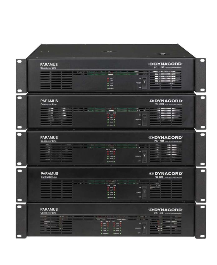
PCL Series | Contractor Line
PCL 1125T | 1225T | 1240T | 1245 | 1415

Owner‘s Manual | Bedienungsanleitung | Mode d‘emploi
CONTENTS

ENGLISH                                      FRANCAISE
IMPORTANT SAFETY INSTRUCTIONS    ...... 3    TABLE DES MATIÉRES                       ...... 22
IMPORTANT SERVICE INSTRUCTIONS   ...... 3    INSTRUCTIONS DE SÉCURITÉ
DESCRIPTION                      ...... 4    IMPORTANTES                              ...... 23
    Unpacking & Warranty         ...... 4    INSTRUCTIONS DE RÉPARATION
    Installation Notes           ...... 4    IMPORTANTES                              ...... 23
FRONT PANEL                      ...... 5    INTRODUCTION                             ...... 24
    Mains Switch                 ...... 5        Déballage et garantie                ...... 24
    Protect                      ...... 5       Remarques concernant l’installation   ...... 24
    Limiter                      ...... 5    FACE AVANT                               ...... 25
    Level Indication             ...... 5        Interrupteur secteur                 ...... 25
    Power                        ...... 5        Protect                              ...... 25
REAR PANEL                       ...... 6        Limiteur                             ...... 25
    Audio Signal Inputs          ...... 6        Indicateur de niveau                 ...... 25
    Level Controls               ...... 6        Power                                ...... 25
    Mode Switch                  ...... 6    PANNEAU ARRIÈRE                          ...... 26
    High Pass Filter             ...... 6        Entrées Signal Audio                 ...... 26
    Loudspeaker Outputs          ...... 7        Contrôles de niveau                  ...... 26
    Mains Fuse                   ...... 8        Sélecteur de Mode                    ...... 26
    Mains Socket                 ...... 8        Filtre Passe-Haut                    ...... 26
    Voltage Selector             ...... 8        Sorties Haut-Parleur                 ...... 27
LF CONNECTION CORDS              ...... 8        Fusible secteur                      ...... 28
MAINS OPERATION & RESULTING                      Prise secteur                        ...... 28
TEMPERATURE                      ...... 9        Sélecteur de tension                 ...... 28
NOTES                            ...... 11   CORDONS DE CONNEXION AUDIO               ...... 28
                                             ALIMENTATION SECTEUR ET
DEUTSCH                                      TEMPÉRATURE RÉSULTANTE                   ...... 29
                                             NOTICES                                  ...... 31
INHALT                           ...... 12
WICHTIGE SICHERHEITSHINWEISE     ...... 13
                                             APPENDIX / ANHANG / APPENDICE
WICHTIGE SERVICEHINWEISE         ...... 13
BESCHREIBUNG                     ...... 14   TECHNICAL SPECIFICATIONS                 ...... 32
   Auspacken & Garantie          ...... 14   BLOCK DIAGRAMM                           ...... 33
   Installationshinweise         ...... 14      PCL 1245 / PCL 1415                   ...... 33
FRONTSEITE                       ...... 15      PCL 1415                              ...... 34
    Netzschalter                 ...... 15      PCL 1240T / PCL 1225T                 ...... 35
    Protect                      ...... 15      PCL 1125T                             ...... 36
    Limiter                      ...... 15   DIMENSIONS                               ...... 37
    Pegelanzeigen                ...... 15
    Power                        ...... 15
RÜCKSEITE                        ...... 16
    Signaleingänge               ...... 16
    Level Regler                 ...... 16
    Mode Schalter                ...... 16
    Hochpassfilter               ...... 16
    Lautsprecherausgänge         ...... 17
    Netzsicherung                ...... 18
    Netzbuchse                   ...... 18
    Spannungswahlschalter        ...... 18
NF-VERBINDUNGSKABEL              ...... 18
NETZBETRIEB & WÄRMEENTWICKLUNG   ...... 19
NOTIZEN                          ...... 21

                                             2
IMPORTANT SAFETY INSTRUCTIONS
The lightning flash with arrowhead symbol, within an equilateral
triangle is intended to alert the user to the presence of uninsulated
”dangerous voltage” within the product’s enclosure that may be of
sufficent magnitude to constitute a risk of electric shock to per-
sons.
The exclamation point within an equilateral triangle is intended to
alert the user to the presence of important operating and
maintance (servicing) instructions in the literature accompanying
the appliance.
1. Read these instructions.
2. Keep these instructions.
3. Heed all warnings.
4. Follow all instructions.
5. Do not use this apparatus near water.
6. Clean only with a dry cloth.
7. Do not cover any ventilation openings. Install in accordance with the manufacturer’s instructions.
8. Do not install near heat sources such as radiators, heat registers, stoves, or other apparatus (including amplifiers) that produce heat.
9. Do not defeat the safety purpose of the polarized or the grounding-type plug. A polarized plug has two blades with one wider than the other. A grounding type
plug has two blades and a third grounding prong. The wide blade or the third prong are provided for your safety. If the provided plug does not fit into your out-
let, consult an electrician for replacement of the obsolete outlet.
10. Protect the power cord from being walked on or pinched particularly at plugs, convenience receptacles, and the point where they exit from the apparatus.
11. Only use attachments/accessories specified by the manufacturer.
12. Use only with the cart, tripod, bracket, or table specified by the manufacturer, or sold with the apparatus. When a cart is used, use caution
when moving the cart/apparatus combination to avoid injury from tip-over.
13. Unplug this apparatus during lightning storms or when unused for a long period of time.
14. Refer all servicing to qualified service personnel. Servicing is required when the apparatus has been damaged in any way, such as power-
supply cord or plug is damaged, liquid has been spilled or orbjects have fallen into the apparatus, the apparatus has been exposed to rain or
moisture, does not operate normally, or has been dropped.
15. Do not expose this equipment to dripping or splashing and ensure that no objects filled with liquids, such as vases, are placed on the equipment.
16. To completely disconnect this equipment from the AC Mains, disconnect the power supply cord plug from the AC receptacle.
17. The mains plug of the power supply cord shall remain readily operable.
18. No naked flame sources, such as lighted candles, should be placed on the apparatus.
19. The product should be connected to a mains socket outlet with a protective earthing connection.
IMPORTANT SERVICE INSTRUCTIONS
CAUTION: These servicing instructions are for use by qualified personnel only. To reduce the risk of
electric shock, do not perform any servicing other than that contained in the Operating Instructions
unless you are qualified to do so. Refer all servicing to qualified service personnel.
1. Security regulations as stated in the IEC 62368-1: 2018, EN 62368-1:2020+A11:2020, UL 62368-1:2019 and CAN/CSA C22.2 No. 62368-1:2019. have to be obeyed when
servicing the appliance.
2. Use of a mains separator transformer is mandatory during maintenance while the appliance is opened, needs to be operated and is connected to the mains.
3. Switch off the power before retrofitting any extensions, changing the mains voltage or the output voltage.
4. The minimum distance between parts carrying mains voltage and any accessible metal piece (metal enclosure), respectively between the mains poles has to
be 3 mm and needs to be minded at all times. The minimum distance between parts carrying mains voltage and any switches or breakers that are not con-
nected to the mains (secondary parts) has to be 6 mm and needs to be minded at all times.
5. Replacing special components that are marked in the circuit diagram using the security symbol (Note) is only permissible when using original parts.
6. Altering the circuitry without prior consent or advice is not legitimate.
7. Any work security regulations that are applicable at the locations where the appliance is being serviced have to be strictly obeyed. This applies also to any
regulations about the work place itself.
8. All instructions concerning the handling of MOS-circuits have to be observed.
NOTE: SAFETY COMPONENT (MUST BE REPLACED BY ORIGINAL PART)
WEEE RECYCLING/DISPOSAL INSTRUCTIONS
The Wheelie Bin symbol found on the product or in the manual indicates that this product must not be disposed of with other waste. It is in our category the
manufacturer’s responsibility to properly dispose of their waste electrical and electronic equipment (WEEE) at the end of its life. Due to the differences in each EU
country’s management of WEEE, please contact your local distributor. We are committed to facilitate our own electronic-waste-management-system, for the free
of charge return of all EVI Audio GmbH products: Telex, DYNACORD, Electro-Voice and RTS. Arrangements are made with the dealer where you purchased the
equipment from, for the returning of all unusable equipment at no cost, to the factory in Straubing, for environmental protective disposal.
Due to line current harmonics, we recommend that you contact your supply authority before connection.DESCRIPTION
Congratulations on your DYNACORD PCL-Series power amplifier purchase! The DYNACORD PCL-
Series power amp line combines outstanding audio performance, exceptional reliability and secure op-
erational safety in a compact 2RU chassis design.
All models in the PCL-Series provide several protection circuits which not only prevent the power
amplifier itself but also the connected loudspeaker systems from being damaged. These protections
include Dynamic Audio Limiters, Inrush Current Limiter, Short Circuit Protection and Thermal Overload
Protection. All PCL-Series power amps feature different hi-pass filters with switch selectable cut-off
frequency to attenuate unwanted low-frequency signals.
Infinitely variable low-noise high performance fans guarantee absolute thermal stability while keeping fan
noise to a minimum. Direct “flow-thru” chassis design allows for a smooth flow of air from front-to-rear,
which allows trouble-free operation even in smaller amp-racks.
Compact high density power supply units with low-leakage toroidal transformers provide extensive
headroom far above the listed power rating. Premium phoenix style screw-lock connectors prevent
accidental disconnection resulting in a more secure connection of audio signal and speaker cables.
All PCL-Series “T” version models are equipped with high performance output transformers also provide
floating outputs for 50V, 70V and 100V installations. These models also provide voltage limiters to
protect the loudspeaker outputs against over-voltage.
Unpacking & Warranty
Carefully open the packaging and take out the power amplifier. Next to the power amplifier itself, the
package also includes this owner’s manual, a mains cord, a warranty certificate, four attachable feet as
well as screwlock connectors for all inputs and outputs. The warranty period is 36 months starting
from the date when receiving the appliance from the dealer. Keep the original invoice, which states
the purchase/delivery date together with the warranty certificate at a safe place.
Installation Notes
First of all, please make sure to check that the voltage selector on the amp’s rear is set to the correct
position matching the installation site’s local mains voltage.
Generally, installing or mounting power amps should be carried out in a way that guarantees continuously
unopposed front-to-rear air circulation. When including an appliance in a closed cabinet or rack shelf
system make sure to provide sufficient ventilation. Leave an air duct of at least 2.5“ x 13“ (up to
the cabinet’s top ventilation louvers) for air circulation between the rear of the power amplifier and
the cabinet’s/rack’s rear wall. Make sure to leave at least 4“ of space above the cabinet or rack
shelf system. Since temperatures inside of a cabinet or rack shelf system can easily rise up to 105 degrees
during operation, carefully considering the environmental temperature maximum values of all other
appliances installed in the same rack shelf system is mandatory (also refer to “Mains Operation &
Resulting Temperature”).
When installing the power amp in a cabinet or rack shelf system, make sure to make use of the
rear mounting facilities to fix the appliance in place and keep the front panel from bending. If
this is not possible, please use mounting-rails instead.
Caution: For problem-free operation do not exceed the environmental temperature maximum
of 105 Deg. F.
The power amplifier has to be protected against: moisture (dripping or splashing water), direct sunlight,
high temperatures or the direct influence of heat sources, high humidity, extensive dust and vibrations.
Condensation on internal parts may occur after transporting the power amplifier from a cold into a warmer
environment. In that case operation is only permissible after the appliance has gained the new temp-
erature (after approximately one hour). If objects or liquids have intruded the power amp’s enclosure,
disconnect the appliance from the mains immediately and contact an authorised service center for
inspection before continuing to operate the unit.
Do not use any sprays or solvents for cleaning the appliance, because they might severely damage
the surface of the enclosure or lead to dangerous fire hazard.
4FRONT PANEL
Mains Switch
Use the mains switch to switch the unit’s power on. A soft-start function prevents inrush
current peaks on the mains, additionally preventing the mains line protection switch from
activating during the amp’s power-on operation. Loudspeaker outputs are activated via
relay switching with a delay of approx. 2 seconds, which effectively eliminates eventual
power-on noise.
During this delay period, the Protect LED lights to confirm correct operation of the
protection circuitry.
Protect (PROT)
A lit Protect LED indicates that one of the integrated protections against thermal overload,
short-circuit … has been activated. The audio channels’ protection circuits operate in-
dependent from each other. At the occurrence of failure or overload conditions the
affected power amp channel is separated from the load connected via output relay,
preventing the connected loudspeaker systems and the power amplifier itself from
being damaged. Whatever caused the fault – e.g. a short-circuited speaker cable – needs
to be remedied. In case of thermal overload you have to wait until the power amplifier
automatically returns to normal operation.
Limiter
The Limit indicator lights as soon as the integrated dynamic limiter is being activated
and the power amp is driven at the clipping limit or generally at its maximum capacity.
Short-term blinking is not a problem, because the internal limiter trims input levels of up
to +21dBu down to a THD+N of approximately 1%. If, on the other hand, this LED lights
constantly, reducing the volume is strongly recommended to prevent the connected
loudspeaker systems from being damaged by probable overload.
Level Indication
The level indicators signify the power amplifier’s current modulation. The -30dB LED
starts lighting at approx. 30dB below full modulation while the -10dB LED lights at
approx. 10dB below full modulation. Shorted speaker cables or the activation of a
protection circuit causes these indicators to go out.
Power
The Power indicator lights when switching the power amplifier on. If the power on LED
does not light please check to make sure the unit is plugged in or that the primary
fuse is not blown. If the fuse is blown please contact an authorized service center.
5REAR PANEL
����� � ������
������� �������
Audio Signal Inputs
The electronically balanced inputs facilitate the connection of external signal sources
(e.g. mixing consoles). When screwed to the power amp, the screwlock connectors
provided with the unit prevent accidental disconnection.
Choosing balanced cables (2 conductors for audio signals + separate shielding mesh)
����� � ������
for LF-signal connection is generally recommended, even when the connected signal
������� �������
source does not provide balanced output signals. This is possible by jointly connecting
“–” conductor and shield on the source side (also refer to “LF-Connection Cords).
CAUTION: The connector marked with a symbol is for connecting the audio cable’s
shielding mesh only.
It is not suited for the connection of the mains cord protective earthing con-
ductor.
Level Controls
The Level Controls allow setting the according power amp channel’s overall
amplification. To prevent distortion in mixing consoles connected to the amp, setting
these controls to a value between -6dB and 0dB is generally recommended. A scale
provides direct indication of the varying additional control attenuation applied to the fixed
internal amplification.
Mode Switch
The Mode Switch allows selecting the power amp’s mode of operation. With the four-
channel model it is possible to independently select channels A and B or C and D.
The single-channel model comes without mode switch.
DUAL: The power amp channels work independently from each other, each re-
producing the audio signals fed to the corresponding input.
PARALLEL: Both channels reproduce the audio signal fed to input A (or C). However,
using the level controls allows individually setting the channel volumes.
BDGD: Audio signals need to be fed to channel A (or C) when in Bridged Mode.
Power amps A and B (or C and D) now work in push-pull operation
delivering doubled output voltage. Please keep in mind to correctly
connect the loudspeaker systems for Bridged Mode operation. (also refer
to “Loudspeaker Outputs”)
High Pass Filter (HPF)
The Hi-Pass filter allows effective attenuation of low bass audio signals. You can choose
from three cut-off frequency settings:
Power Amps with low impedance outputs Power Amps with output transformer
300Hz, 12dB/oct., BW 300Hz, 12dB/oct., BW
50Hz, 12dB/oct., BW 70Hz, 12dB/oct., BW
OFF (no Hi-Pass filter) 50Hz, 18dB/oct., BW
As a basic principle, all models with output transformer have a 50Hz Hi-Pass filter in the
audio signal path to protect the transformer from being driven into saturation by high
level low-frequency signals.
6REAR PANEL
Loudspeaker Outputs
The speaker output jacks are suitable for connecting speaker cables with a maximum diameter of 2.5
mm2. The provided screwlock connectors can be screwed to the power amp to prevent inadvertent
disconnection. Power amps offer low impedance outputs and / or floating outputs (ISOLATED
OUTPUTS) with nominal voltages of 50V, 70V and 100V, depending on the amp model.
Caution: The symbol of a FLASH at the loudspeaker connectors indicates that these outputs
may carry high voltages which, when getting in contact with, can cause serious harm.
Establishing connections at these outputs is only permissible for skilled persons who
have been instructed on how to do so.
Never connect a hot output to a ground or another hot output! Always turn off the
amplifier before making connections!
PCL 1245 & PCL 1415
Loudspeaker systems connected to channels A and B (or C and D) have to be
connected according to the polarity indicated. Please, make sure to mind the
minimal impedance of 4 ohms per channel.
For bridged operation, the load has to be connected according to the BRIDGED-
label and the Mode switch needs to be set to “Bridged”. Please, make sure to
keep in mind that in Bridged Mode the minimal impedance is 8 ohms and that
the input audio signal has to be fed to channel A (or C).
PCL 1125T, PCL 1225T & PCL 1240T
Integrated audio output transformers convert the power amp’s nominal output voltage to 50V, 70V and
100V. The amplifier models PCL 1225T and PCL 1240T present all voltages simultaneously at the
floating outputs so that the power amp channels can be used in any combination of possible output
voltages. Mixed operation of low-impedance speaker systems and floating loudspeaker lines on a single
power amp channel is possible as well.
The use of loudspeaker systems with 100V or 70V matching transformers to reduce the effects of cable
loss is recommended when the distance between power amp and speaker systems exceeds 165 feet.
In addition, this also facilitates distributing the output power among loudspeakers.
As many loudspeaker systems as possible can be connected, as long as the speaker network’s overall
power consumption does not exceed the power amp’s rated output power while at the same time not
falling below the nominal load impedance of the power amp outputs. Please refer to specifications in
the appendix for individual values of the rated output power and nominal load impedance of power amp
outputs.
100V 100V 16 x 25W
25W 25W
100V 100V 66 x 6W
6W 6W
Configuration example: PCL 1240T with 100V speaker systems connected.
Maximum working loads with 25W/100V and 6W/100V loudspeaker systems.
7REAR PANEL
Mains Fuse
Under normal circumstance, the mains fuse blows only in the event of failure. When
replacing the fuse, make sure to use a fuse of the same type with identical prearcing
amperage, voltage and blow characteristics. If the mains fuse blows repeatedly, please
contact an authorized service centre.
Mains Socket
Please, make sure to check whether the voltage selector shows the correct mains
voltage that matches the local mains supply at the installation site. An appropriate mains
cord is included in the package.
Caution: This appliance has no user serviceable parts inside. Leave servicing to
a qualified professional.
Voltage Selector
Covered selector switch which shows the correct mains voltage for the unit.
LF-connection cords
Choosing balanced cables (two conductors for audio signals plus separate shielding mesh) is
recommended for LF-signal connection. Although connecting unbalanced cables to the power amplifier
inputs is possible as well, using balanced cables is always preferable.
A great number of today’s audio appliances provide balanced outputs carried out via XLR-type
connectors. With balanced cabling, the shield interconnects all metal enclosure parts and therefore
efficiently eliminates the introduction of external interference – mostly noise and hum.
Wiring examples
XLR-female amp input
connector
Cable to connect signal source with balanced XLR outputs.
phone jack amp input
connector
Cable to connect signal source with unbalanced outputs.
8MAINS OPERATION & RESULTING TEMPERATURE
Mains Operation
The following tables provide a useful(2)aid in determining power supply and cabling requirements. Column
“1/8 max. output power into 4 ohms ” states the values to be used for normal operation. These results
were measured with the power amplifier being operated at maximum output and a Pink Noise signal
according to EN62368 applied at the input, which approximately represents the strain of an audio signal
driving the power amp at maximum modulation.
Temperatures inside of the power amplifier
The power drawn from the mains network is converted into acoustic output to feed the connected
loudspeaker systems plus heat. The difference between drawn power and dispensed power is referred
to as leakage power or dissipation (PD). The amount of heat resulting from power dissipation might
remain inside of a rack-shelf and needs to be diverted using appropriate measures. The following table
is meant as auxiliary means for calculating temperatures inside of a rack-shelf system/cabinet and the
ventilation efforts necessary.
The column “PD” lists the leakage power in relation to different operational states. The column “BTU/hr”
shows the dispensed heat amount per hour.
PCL 1245 Umains Imains Pmains Pout PD BTU/
[V] [A] [W] [W] [W] hr(3)
idle 230 0,2 28 0 28 96
(1)
Max. output power into 8ohms 230 5,4 923 2x300 323 1102
(1)
Max. output power into 4ohms 230 8,8 1605 2x480 645 2201
(1)
1/3 max. output power into 4ohms 230 5,6 953 2x160 633 2160
(1)
1/8 max. output power into 4ohms 230 3,7 598 2x60 478 1631
(2)
1/8 max. output power into 4ohms 230 3,2 530 2x60 410 1399
(2) (4)
1/8 max. output power into 4ohms 253 3,6 629 2x73 484 1651
(1)
Normal Mode (-10dB) into 4ohms 230 3,2 550 2x48 454 1549
(1)
Rated output power (0dB, rated) into 4ohms 230 8,1 1482 2x450 582 1986
(1)
Alert-Mode (-3dB) into 4ohms 230 6,1 1065 2x225 615 2098
PCL 1415 Umains Imains Pmains Pout PD BTU/
[V] [A] [W] [W] [W] hr(3)
idle 230 0,4 54,7 0 55 187
(1)
Max. output power into 8ohms 230 3,9 653 4x100 253 863
(1)
Max. output power into 4ohms 230 6,3 1126 4x160 486 1658
(1)
1/3 max. output power into 4ohms 230 4,0 665 4x53 452 1541
(1)
1/8 max. output power into 4ohms 230 2,7 428 4x20 348 1187
(2)
1/8 max. output power into 4ohms 230 2,4 385 4x20 305 1041
(2) (4)
1/8 max. output power into 4ohms 253 2,6 450 4x24 353 1205
(1)
Normal Mode (-10dB) into 4ohms 230 2,4 385 4x16 321 1095
(1)
Rated output power (0dB, rated) into 4ohms 230 6,1 1080 4x150 490 1638
(1)
Alert-Mode (-3dB) into 4ohms 230 4,6 790 4x75 490 1672
(1)
Sine wave 1kHz
(2)
Pink noise acc. to EN 62368
(3)
1BTU = 1055.06J = 1055.06Ws
(4)
10% mains over voltage
(5)
PD = Power dissipation
The following factors allow direct proportional calculation of the mains current (Imains) for different mains
supply voltages: 100V = 2,3; 120V = 1,9; 220V = 1,05; 240V = 0,96
9MAINS OPERATION & RESULTING TEMPERATURE
PCL 1240T - 100V output Umains Imains Pmains Pout PD BTU/
[V] [A] [W] [W] [W] hr(3)
idle 230 0,3 44,3 0 44 151
(1)
Max. output power into 25ohms 230 8,9 1643 2x430 783 2672
(1)
1/3 max. output power into 25ohms 230 5,5 952 2x143 665 2270
(1)
1/8 max. output power into 25ohms 230 3,7 602 2x54 495 1687
(2)
1/8 max. output power into 25ohms 230 3,3 545 2x54 438 1493
(2) (4)
1/8 max. output power into 25ohms 253 3,7 646 2x65 516 1760
(1)
Normal-Mode (-10dB) into 25ohms 230 3,3 540 2x43 454 1549
(1)
Rated output power (0dB, rated) into 25ohms 230 8,5 1550 2x400 750 2559
(1)
Alert-Mode (-3dB) into 25ohms 230 6,3 1119 2x200 719 2453
PCL 1225T - 100V output Umains Imains Pmains Pout PD BTU/
[V] [A] [W] [W] [W] hr(3)
idle 230 0,2 31,6 0 32 108
(1)
Max. output power into 40ohms 230 5,5 960 2x270 420 1433
(1)
1/3 max. output power into 40ohms 230 3,5 571 2x90 391 1334
(1)
1/8 max. output power into 40ohms 230 2,3 365 2x34 298 1015
(2)
1/8 max. output power into 40ohms 230 2,1 330 2x34 263 896
(2) (4)
1/8 max. output power into 40ohms 253 2,3 385 2x41 303 1035
(1)
Normal-Mode (-10dB) into 40ohms 230 2,1 328 2x27 274 935
(1)
Rated output power (0dB, rated) into 40ohms 230 5,4 929 2x250 429 1464
(1)
Alert-Mode (-3dB) into 40ohms 230 4,0 668 2x125 418 1426
PCL 1125T - 100V output Umains Imains Pmains Pout PD BTU/
[V] [A] [W] [W] [W] hr(3)
idle 230 0,2 21,7 0 22 74
(1)
Max. output power into 40ohms 230 2,8 487 1x270 217 740
(1)
1/3 max. output power into 40ohms 230 1,8 289 1x90 199 679
(1)
1/8 max. output power into 40ohms 230 1,2 182 1x34 148 506
(2)
1/8 max. output power into 40ohms 230 1,1 170 1x34 136 465
(2) (4)
1/8 max. output power into 40ohms 253 1,2 197 1x41 156 533
(1)
Normal-Mode (-10dB) into 40ohms 230 1,1 164 1x27 137 467
(1)
Rated output power (0dB, rated) into 40ohms 230 2,7 471 1x250 221 754
(1)
Alert-Mode (-3dB) into 40ohms 230 2,0 339 1x125 214 730
(1)
Sine wave 1kHz
(2)
Pink noise acc. to EN 62368
(3)
1BTU = 1055.06J = 1055.06Ws
(4)
10% mains over voltage
(5)
PD = Power dissipation
The following factors allow direct proportional calculation of the mains current (Imains) for different mains
supply voltages: 100V = 2,3; 120V = 1,9; 220V = 1,05; 240V = 0,96
For power amp models with integrated transformers, the listed values for the 100V outputs are equally
applicable for the 70V, 50V and for the low-impedance outputs as long as the connected load is
equivalent as well.
10NOTES 11
INHALT

         WICHTIGE SICHERHEITSHINWEISE     .......................   13
         WICHTIGE SERVICEHINWEISE         .......................   13
         BESCHREIBUNG                     .......................   14
            Auspacken & Garantie          .......................   14
            Installationshinweise         .......................   14
         FRONTSEITE                       .......................   15
             Netzschalter                 .......................   15
             Protect                      .......................   15
             Limiter                      .......................   15
             Pegelanzeigen                .......................   15
             Power                        .......................   15
         RÜCKSEITE                        .......................   16
             Signaleingänge               .......................   16
             Level Regler                 .......................   16
             Mode Schalter                .......................   16
             Hochpassfilter               .......................   16
             Lautsprecherausgänge         .......................   17
             Netzsicherung                .......................   18
             Netzbuchse                   .......................   18
             Spannungswahlschalter        .......................   18
         NF-VERBINDUNGSKABEL              .......................   18
         NETZBETRIEB & WÄRMEENTWICKLUNG   .......................   19
         NOTIZEN                          .......................   21
         TECHNISCHE DATEN                 .......................   32
         BLOCK DIAGRAMM                   .......................   33
             PCL 1245 / PCL 1415          .......................   33
             PCL 1415                     .......................   34
             PCL 1240T / PCL 1225T        .......................   35
             PCL 1125T                    .......................   36
         ABMESSUNGEN                      .......................   37

                                12
WICHTIGE SICHERHEITSHINWEISE
Das Blitzsymbol innerhalb eines gleichseitigen
Dreiecks soll den Anwender auf nicht isolierte Lei-
tungen und Kontakte im Geräteinneren hinweisen,
an denen hohe Spannungen anliegen, die im Fall
einer Berührung zu lebensgefährlichen Strom-
schlägen führen können.
Das Ausrufezeichen innerhalb eines gleichseitigen
Dreiecks soll den Anwender auf wichtige Bedie-
nungs- sowie Servicehinweise in der zum Gerät
gehörenden Literatur aufmerksam machen.
1. Lesen Sie diese Hinweise.
2. Heben Sie diese Hinweise auf.
3. Beachten Sie alle Warnungen.
4. Richten Sie sich nach den Anweisungen.
5. Betreiben Sie das Gerät nicht in unmittelbarer Nähe von Wasser.
6. Verwenden Sie zum Reinigen des Gerätes ausschließlich ein trockenes Tuch.
7. Verdecken Sie keine Lüftungsschlitze. Beachten Sie bei der Installation des Gerätes stets die entsprechenden Hinweise des Herstellers.
8. Vermeiden Sie die Installation des Gerätes in der Nähe von Heizkörpern, Wärmespeichern, Öfen oder anderer Wärmequellen.
9. Achtung: Gerät nur an Netzsteckdose mit Schutzleiteranschluss betreiben. Setzen Sie die Funktion des Schutzleiteranschlusses des
mitgelieferten Netzanschlusskabels nicht außer Kraft. Sollte der Stecker des mitgelieferten Kabels nicht in Ihre Netzsteckdose passen, setzen
Sie sich mit Ihrem Elektriker in Verbindung.
10. Sorgen Sie dafür, dass das Netzkabel nicht betreten wird. Schützen Sie das Netzkabel vor Quetschungen insbesondere am Gerätestecker und
am Netzstecker.
11. Verwenden Sie mit dem Gerät ausschließlich Zubehör/Erweiterungen, die vom Hersteller hierzu vorgesehen sind.
12. Verwenden Sie zusammen mit dieser Komponente nur vom Hersteller dazu vorgesehene oder andere geeignete Lastkarren,
Stative, Befestigungsklammern oder Tische, die Sie zusammen mit dem Gerät erworben haben. Achten Sie beim Transport mittels
Lastkarren darauf, dass das transportierte Equipment und der Karren nicht umfallen und möglicherweise Personen- und/oder
Sachschäden verursachen können.
13. Ziehen Sie bei Blitzschlaggefahr oder bei längerem Nichtgebrauch den Netzstecker.
14. Überlassen Sie sämtliche Servicearbeiten und Reparaturen einem ausgebildeten Kundendiensttechniker. Servicearbeiten sind
notwendig, sobald das Gerät auf irgendeine Weise beschädigt wurde, wie z.B. eine Beschädigung des Netzkabels oder des Netzsteckers, wenn
eine Flüssigkeit in das Gerät geschüttet wurde oder ein Gegenstand in das Gerät gefallen ist, wenn das Gerät Regen oder Feuchtigkeit
ausgesetzt wurde, oder wenn es nicht normal arbeitet oder fallengelassen wurde.
15. Stellen Sie bitte sicher, dass kein Tropf- oder Spritzwasser ins Geräteinnere eindringen kann. Platzieren Sie keine mit Flüssigkeiten gefüllten
Objekte, wie Vasen oder Trinkgefäße, auf dem Gerät.
16. Um das Gerät komplett spannungsfrei zu schalten, muss der Netzstecker gezogen werden.
17. Beim Einbau des Gerätes ist zu beachten, dass der Netzstecker leicht zugänglich bleibt.
18. Stellen Sie keine offenen Brandquellen, wie z.B. brennende Kerzen auf das Gerät.
19. Dieses SCHUTZKLASSE I Gerät muss an eine NETZ-Steckdose mit Schutzleiter-Anschluss angeschlossen werden.
WICHTIGE SERVICEHINWEISE
ACHTUNG: Diese Servicehinweise sind ausschließlich zur Verwendung durch qualifiziertes Servicepersonal. Um die Gefahr
eines elektrischen Schlages zu vermeiden, führen Sie keine Wartungsarbeiten durch, die nicht in der
Bedienungsanleitung beschrieben sind, außer Sie sind hierfür qualifiziert. Überlassen Sie sämtliche
Servicearbeiten und Reparaturen einem ausgebildeten Kundendiensttechniker.
1. Bei Reparaturarbeiten im Gerät sind die Sicherheitsbestimmungen nach IEC 62368-1: 2018, EN 62368-1:2020+A11:2020, UL 62368-1:2019 and
CAN/CSA C22.2 No. 62368-1:2019.einzuhalten.
2. Bei allen Arbeiten, bei denen das geöffnete Gerät mit Netzspannung verbunden ist und betrieben wird, ist ein Netz-Trenntransformator zu
verwenden.
3. Vor einem Umbau mit Nachrüstsätzen, Umschaltung der Netzspannung oder sonstigen Modifikationen ist das Gerät stromlos zu schalten.
4. Die Mindestabstände zwischen netzspannungsführenden Teilen und berührbaren Metallteilen (Metallgehäuse) bzw. zwischen den Netzpolen
betragen 3 mm und sind unbedingt einzuhalten.
5. Die Mindestabstände zwischen netzspannungsführenden Teilen und Schaltungsteilen, die nicht mit dem Netz verbunden sind (sekundär),
betragen 6 mm und sind unbedingt einzuhalten.
6. Spezielle Bauteile, die im Stromlaufplan mit dem Sicherheitssymbol gekennzeichnet sind, (Note) dürfen nur durch Originalteile ersetzt werden.
7. Eigenmächtige Schaltungsänderungen dürfen nicht vorgenommen werden.
8. Die am Reparaturort gültigen Schutzbestimmungen der Berufsgenossenschaften sind einzuhalten. Hierzu gehört auch die Beschaffenheit des
Arbeitsplatzes.
9. Die Vorschriften im Umgang mit MOS-Bauteilen sind zu beachten.
NOTE: SAFETY COMPONENT (MUST BE REPLACED BY ORIGINAL PART)
Hinweise zur Entsorgung/Wiederverwendung gemäß WEEE
Das auf unserem Produkt und im Handbuch abgedruckte Mülltonnensymbol weist daraufhin, dass dieses Produkt nicht gemeinsam mit dem Haushaltsmüll entsorgt werden darf. Für
die korrekte Entsorgung der Elektro- und Elektronik-Altgeräte (WEEE) am Ende ihrer Nutzungsdauer ist in unserer Kategorie der Hersteller verantwortlich. Aufgrund
unterschiedlicher Regelungen zur WEEE-Umsetzung in den einzelnen EU-Staaten bitten wir Sie, sich an Ihren örtlichen Händler zu wenden. Wir haben ein eigenes System zur
Verarbeitung elektronischer Abfälle und gewährleisten die kostenfreie Entgegennahme aller Produkte der EVI Audio GmbH: Telex, DYNACORD, Electro-Voice und RTS. Wir haben mit
dem Händler, bei dem Sie Ihr Produkt gekauft haben, eine Vereinbarung getroffen, dass alle nicht mehr verwenbaren Geräte zur umweltgerechten Entsorgung kostenfrei an das Werk
in Straubing zurückgeschickt werden.
Bitte kontaktieren Sie vor dem Anschluss an die Spannungsversorgung Ihr Energieversorgungsunternehmen bezüglich Oberwellen.BESCHREIBUNG
Herzlichen Glückwunsch! Sie haben sich mit einer Endstufe von DYNACORD für ein Gerät modern-
ster Technologie entschieden. Die Endstufen der PCL-Serie vereinen überragende Audio Performance
mit höchster Zuverlässigkeit und Betriebssicherheit.
Zahlreiche Schutzschaltungen, die für jeden Kanal individuell vorhanden sind, schützen nicht nur die
Endstufen, sondern auch die angeschlossenen Lautsprecher. Zu diesen Protections gehören dynami-
sche Audio-Limiter, Einschalt- und Kurzschlußstrombegrenzung und Temperaturüberwachung der End-
stufenblöcke.
Zur Unterdrückung von tieffrequenten Signalen sind alle Endstufen der PCL-Serie mit verschiedenen
Hochpassfiltern ausgestattet, deren Trennfrequenz über Schalter gewählt werden kann.
Die thermische Stabilität wird durch stufenlose Hochleistungslüfter mit niedrigem Geräuschpegel ge-
währleistet. Die Luftführung ist Front-to-Rear, was den problemlosen Betrieb in grossen und schmalen
Endstufenracks ermöglicht.
Durch grosszügig dimensionierte Netzteile mit streuarmen Ringkerntransformatoren wird ein grosser
Headroom, weit oberhalb der ausgewiesenen Nennleistung, erzielt. Hochwertige Schraubsteckverbin-
der, die vor unbeabsichtigtem Entfernen geschützt werden können, garantieren eine sichere Verbindung
von Signal- und Lautsprecherleitungen.
Modelle, die mit Hochleistungs-Ausgangstransformatoren bestückt sind, stellen zusätzlich zu den nieder-
ohmigen Ausgängen, die Lautsprecherausgänge erdfrei, für 50V, 70V und 100V Installationen zur Ver-
fügung. Zum Schutz vor zu hoher Spannung am Lautsprecherausgang sind diese Geräte zusätzlich mit
Spannungslimitern ausgestattet.
Auspacken und Garantie
Öffnen Sie die Verpackung und entnehmen Sie die Endstufe. Zusätzlich zu dieser Bedienungsanleitung
liegen dem Gerät ein Netzkabel, die Garantiekarte, vier Gerätefüsse und Schraub-Steckverbinder für
alle Ein- und Ausgänge bei. Sie haben auf das Gerät 36 Monate Garantie, die ab dem Zeitpunkt der
Aushändigung durch den Händler gilt. Bewahren Sie zur Garantiekarte auch den Kaufbeleg, der den
Termin der Übergabe festlegt, auf.
Installationshinweise
Prüfen Sie als Erstes, ob der Spannungswahlschalter auf der Geräterückseite in der richtigen Position
für die Netzspannung in Ihrem Land steht.
Generell sind die Endstufen so aufzustellen oder zu montieren, dass die Luftzufuhr an der Frontseite
und die Entlüftung an der Geräterückseite nicht behindert wird. Für den Einbau in Gehäuse und Ge-
stellschränke ist zu beachten, daß eine ausreichende Belüftung der Geräte möglich ist. Zwischen der
Endstufen Rückseite und der Schrank/Rack-Innenseite ist ein freier Luftkanal bis zur oberen Rack- oder
Schrankentlüftung von mindestens 60mm x 330mm vorzusehen. Oberhalb des Schrankes soll ein freier
Raum von mindestens 100mm für die Entlüftung vorgesehen werden. Da beim Betrieb die Temperatur
im Gehäuse- oder Schrank bis zu 40°C ansteigen kann, muß die maximal zulässige Umgebungstempe-
ratur der übrigen im Gestellschrank befindlichen Geräte beachtet werden (siehe „NETZBETRIEB UND
WÄRMEENTWICKLUNG“).
Um ein Verwinden der Frontblende zu verhindern, sollte die Endstufe beim Einbau in Gestellschränke in
jedem Fall auch über die rückseitigen Befestigungsmöglichkeiten mit dem Rack verschraubt werden. Ist
dies nicht möglich sollten Einbauschienen verwendet werden.
Achtung: Die maximale Umgebungstemperatur von +40°C soll für störungsfreien Betrieb nicht
überschritten werden.
Die Endstufe ist zu schützen vor: Tropf- oder Spritzwasser, direkter Sonnenbestrahlung, hoher Umge-
bungstemperatur oder unmittelbarer Einwirkung von Wärmequellen, hoher Luftfeuchtigkeit, starken
Staubablagerungen und starken Vibrationen. Wenn die Endstufe direkt von einem kalten an einen
warmen Ort gebracht wird, kann sich Feuchtigkeit auf elektronischen Bauteilen niederschlagen. Das
Gerät darf erst in Betrieb genommen werden, wenn es sich auf die geänderte Temperatur erwärmt hat
(nach etwa einer Stunde). Sollte ein fester Gegenstand oder Flüssigkeit in das Gehäuse gelangen,
trennen Sie bitte das Gerät vom Netz und lassen es von einer autorisierten Servicestelle überprüfen,
bevor Sie es weiterverwenden.
Zur Reinigung des Gerätes dürfen keine Sprühmittel verwendet werden, da diese dem Gerät schaden
oder sich plötzlich entzünden können.
14FRONTSEITE
Netzschalter
Mit dem Netzschalter wird das Gerät eingeschaltet. Eine Softstart-Schaltung vermei-
det dabei Einschaltstromspitzen auf der Netzleitung. Dadurch wird verhindert, dass der
Leitungsschutzschalter des Stromnetzes beim Einschalten der Endstufe anspricht. Die
Lautsprecher werden über die Ausgangsrelais um ca. 2 Sekunden verzögert zugeschal-
tet, wodurch etwaige Einschaltgeräusche effektiv unterdrückt werden.
Zur Bestätigung der einwandfreien Funktion aller Schutzschaltungen, leuchtet während
dieser Verzögerung die Protect LED.
Protect (PROT)
Leuchtet eine der Protect Anzeigen, dann hat eine der internen Schutzschaltungen wie
Übertemperatur, Kurzschluss, ... angesprochen. Die Schutzschaltungen der einzelnen
Kanäle arbeiten unabhängig voneinander. Der jeweilige Endstufenkanal wird in diesem
Fall über das Ausgangsrelais von der Last getrennt, um Schäden an den Lautsprechern
oder der Endstufe selbst zu verhindern. Die Fehlerursache, beispielsweise eine kurzge-
schlossene Lautsprecherleitung, muss beseitigt werden. Bei Überhitzung muss einige
Zeit gewartet werden, bis die Endstufe sich selbständig wieder in den normalen Be-
triebszustand schaltet.
Limiter
Leuchtet eine der Limit LED‘s, so spricht der dynamische Limiter des jeweiligen Kanals an.
Ist dies der Fall, wird die Endstufe an der Aussteuerungsgrenze oder generell im Grenz-
bereich betrieben. Kurzzeitiges Aufleuchten ist dabei unproblematisch, da der interne
Limiter Eingangspegel bis +21dBu auf einen Klirrfaktor von ca. 1% ausregeln kann.
Leuchtet diese LED jedoch dauerhaft, sollte die Lautstärke reduziert werden um
Überlastungsschäden der angeschlossenen Lautsprecherboxen zu vermeiden.
Pegelanzeigen
An den Pegelanzeigen wird die momentane Aussteuerung der Endstufe dargestellt.
Die -30dB LED beginnt ca. 30dB unter Vollaussteuerung zu leuchten. Die -10dB LED
entsprechend ca. 10dB unter Vollaussteuerung. Bei Kurzschluss von Lautsprecher-
leitungen oder Ansprechen einer Schutzschaltung verlöschen diese Anzeigen.
Power
Die Power Anzeige leuchtet auf, wenn die Endstufe eingeschaltet ist. Falls die LED
nicht leuchtet, ist das Gerät nicht mit dem Stromnetz verbunden, oder die Primärsicher-
ung defekt. In diesem Fall wenden Sie sich bitte an eine DYNACORD Servicestelle.
15RÜCKSEITE
����� � ������
������� �������
Signaleingänge
An den elektronisch symmetrischen Eingängen werden die Signalquellen (z.B. Mischpult)
angeschlossen. Die im Lieferumfang enthaltenen Steckverbinder können mit der End-
stufe verschraubt werden um ein versehentliches Entfernen zu verhindern.
����� � ������
Die verwendeten NF-Kabel sollten generell symmetrisch (2 Signaladern + Schirmgefle-
������� �������
cht) ausgeführt sein, auch wenn die Signalquelle kein symmetrisches Ausgangssignal
zur Verfügung stellt. In diesem Fall werden „-“ - Leitung und Schirmgeflecht auf der Quellen-
seite verbunden (siehe „NF-Verbindungskabel“).
Achtung: Der Anschluß mit dem Symbol ist zur Verbindung mit dem Schirmgeflecht
des Signalkabels gedacht.
Über diesen Anschluß darf keine Schutzleiterverbindung hergestellt werden.
Level Regler
Mit den Level Reglern kann die Gesamtverstärkung des jeweiligen Endstufenkanals ein-
gestellt werden. Zur Vermeidung von Verzerrungen in vorgeschalteten Mischpulten sollten
diese Regler normalerweise zwischen -6dB und 0dB stehen. Die Beschriftung zeigt un-
mittelbar die zusätzliche Reglerdämpfung mit der die intern-festgelegte Verstärkung
verändert wird.
Mode Schalter
Mit dem Mode Schalter kann die Betriebsart der Endstufe eingestellt werden. Beim vier-
kanaligen Modell kann für die Kanäle A und B, sowie C und D separat gewählt werden.
Das einkanalige Modell hat keinen Mode Schalter.
DUAL: Die Endstufenkanäle arbeiten unabhängig voneinander und geben das am
jeweiligen Eingang eingespeiste Signal wieder.
PARALLEL: Beide Kanäle geben das am Eingang A (bzw. C) anliegende Signal wieder.
Die Lautstärke der Kanäle kann jedoch weiterhin unabhängig voneinander
über die Level-Regler eingestellt werden.
BDGD: Im Bridged Modus muss in den Kanal A (bzw. C) eingespeist werden. Die
Endstufen A und B (bzw. C und D) arbeiten dann im Gegentakt mit doppel-
ter Ausgangsspannung. Beachten Sie, dass die Lautsprecher im Bridged
Betrieb entsprechend angeschlossen werden müssen (siehe „Lautsprech-
erausgänge“).
Hochpassfilter (HPF)
Mit dem Hochpassfilter können tieffrequente Signale unterdrückt werden. Die Einsatzfre-
quenz ist in drei Stufen schaltbar:
Endstufen mit niederohmigen Ausgängen Endstufen mit Ausgangsübertrager
300Hz, 12dB/oct., BW 300Hz, 12dB/oct., BW
50Hz, 12dB/oct., BW 70Hz, 12dB/oct., BW
OFF (kein Hochpassfilter) 50Hz, 18dB/oct., BW
Alle Modelle mit Ausgangsübertrager haben generell ein 50Hz Hochpassfilter im Signal-
weg, da tieffrequente Signale mit hohem Pegel den Übertrager in die Sättigung treiben
können.
16RÜCKSEITE
Lautsprecherausgänge
An den Ausgangsbuchsen können Lautsprecherkabel mit einem maximalen Querschnitt von 2.5mm² an-
geschlossen werden. Die im Lieferumfang enthaltenen Steckverbinder können mit der Endstufe ver-
schraubt werden um ein versehentliches Entfernen zu verhindern. Je nach Typ der Endstufe stehen
niederohmige Ausgänge und / oder potentialfreie Ausgänge (ISOLATED OUTPUTS) mit den Nenn-
spannungen 50V, 70V und 100V zur Verfügung.
Vorsicht: Die mit dem Blitzsymbol gekennzeichneten Ausgänge können BERÜHRUNGSGE-
FÄHRLICHE Spannungen annehmen. An diese ANSCHLUSSSTELLEN angeschlossene Leitung-
en, müssen durch eine UNTERWIESENE PERSON verlegt werden.
Verbinden Sie niemals einen Endstufenausgang mit Masse oder einen anderen Endstufenaus-
gang. Schalten Sie das Gerät immer aus, bevor Sie Leitungen anschliessen.
PCL 1245 & PCL 1415
Lautsprecher für Kanal A & B (bzw. C & D) werden entsprechend der angege-
benen Polarität angeschlossen. Beachten Sie, dass die minimale Impe-
danz für jeden Kanal 4 Ohm beträgt.
Für den Brückenbetrieb muß die Last gemäß dem Aufdruck BRIDGED an-
geschlossen und der Mode Schalter auf Bridged gestellt werden. Beachten
sie, dass die minimale Impedanz im Brückenbetrieb 8 Ohm beträgt und das
Eingangssignal an Kanal A (bzw. C) eingespeist werden muss.
PCL 1125T, PCL 1225T & PCL 1240T
Über eingebaute Audio-Ausgangsübertrager wird die Nennausgangsspannung der Endstufe auf die
Spannungen 50V, 70V und 100V für Lautsprechernetze transformiert. Bei den Modellen PCL 1225T und
PCL 1240T stehen alle Spannungen gleichzeitig potentialfrei zur Verfügung. Die Endstufenkanäle können
in beliebigen Kombinationen der möglichen Ausgangsspannungen verwendet werden. Ein gemischter
Betrieb an einem Endstufenkanal von niederohmigen Lautsprechersystemen und erdfreien Lautspre-
cherlinien ist möglich.
Wenn die Entfernung zwischen Endstufe und Lautsprecher mehr als 50m beträgt, wird empfohlen,
Lautsprecher mit 100V oder 70V Anpassungsübertrager zu verwenden um die Leitungsverluste zu
verringern. Dadurch wird auch eine einfache Verteilung der Ausgangsleistung auf die einzelnen
Systeme ermöglicht.
Es können maximal so viele Lautsprecher angeschlossen werden, bis die Gesamtleistungsauf-
nahme des Lautsprechernetzes dem Nennleistungswert der Endstufe entspricht, wobei der Nenn-
lastwiderstand der Endstufenausgänge nicht unterschritten werden soll. Die Nennleistungswerte
sowie die Nennlastwiderstände der einzelnen Ausgänge entnehmen Sie bitte den Technischen
Daten im Anhang.
100V 100V 16 x 25W
25W 25W
100V 100V 66 x 6W
6W 6W
Beispielbeschaltung PCL 1240T mit 100V Lautsprechern. Maximale Auslastung mit
Lautsprechern 25W/100V und 6W/100V.
17RÜCKSEITE
Netzsicherung
Die Netzsicherung löst unter normalen Umständen nur bei einem Fehlerfall aus. Die
Sicherung darf nur gegen eine gleichwertige Sicherung mit gleicher Strom-,
Spannungs- und Auslösecharakteristik getauscht werden. Sollte die Netzsicherung
wiederholt durchbrennen, kontaktieren Sie bitte eine Servicestelle.
Netzbuchse
Prüfen Sie bitte vor dem Anschließen, ob der Spannungswahlschalter die für Ihr
Land geltende Netzspannung zeigt. Ein passendes Netzkabel ist im Lieferumfang
enthalten.
Achtung: Das Gerät enthält keine vom Anwender zu wartenden Teile. Servicear-
beiten dürfen nur von qualifizertem Fachpersonal durchgeführt werden.
Spannungswahlschalter
Abgedeckter Schiebeschalter der Ihnen die passende Netzspannung für das Gerät
zeigt.
NF-Verbindungskabel
Als NF-Verbindung wählen Sie am besten symmetrisch ausgelegte Kabel (2 Signaladern + Schirmge-
flecht). Obwohl alle Endstufeneingänge auch unsymmetrisch beleget werden können, stellt ein
symmetrisch ausgeführtes NF Verbindungskabel die bessere Alternative zu einer unsymmetrischen
Verbindung dar.
Die meisten Audiogeräte verfügen über symmetrisch aufgebaute XLR-Ausgänge. Der Schirm im Kabel
verbindet bei symmetrischer Signalführung alle metallischen Gehäuse und verhindert dadurch
lückenlos ein Einkoppeln von externen Störsignalen, im wesentlichen Brummen, auf den Audio-
signalpfad.
Beispiele für NF-Kabel
XLR-Stecker Endstufen-
eingang
Anschlusskabel für Geräte mit symmetrischen XLR-Ausgängen
Mono- Endstufen-
Klinkenstecker eingang
Anschlusskabel für Geräte mit unsymmetrischen Ausgängen
18NETZBETRIEB & WÄRMEENTWICKLUNG
Netzbetrieb
Mit Hilfe der folgenden Tabellen können die Anforderungen für Stromversorgung und Zuleitungen bestim-
mt werden. Für normalen Betrieb können die Werte der Spalte „1/8 max. Ausgangsleistung an 4Ohm(2)“
verwendet werden. Die Endstufe wurde hier mit Rosa Rauschen gem. EN62368 bei 1⁄8 der maximalen
Ausgangsleistung betrieben. Dies entspricht etwa der Belastung wenn die Endstufe mit Musiksignal an
der Aussteuerungsgrenze betrieben wird.
Wärmeentwicklung in der Endstufe
Die vom Stromnetz aufgenommene Leistung wird in Ausgangsleistung für die Lautsprecher & Wärme
umgewandelt. Die Differenz aus aufgenommener Leistung und abgegebener Leistung nennt
man Verlustleistung (PV). Die durch Verluste entstehende Wärmemenge verbleibt u.U. im Rack und
muss durch geeignete Massnahmen abgeleitet werden. Zur Berechnung der Wärmeverhältnisse
im Rack/Schrank bzw. nötiger Abluftmassnahmen kann die nachfolgende Tabelle benutzt werden.
Die Spalte PV zeigt die Verlustleistung bei verschiedenen Betriebszuständen. Die Spalte BTU/hr
zeigt die abgegebene Wärmemenge je Stunde.
PCL 1245 UNetz INetz PNetz PAus PV BTU/
[V] [A] [W] [W] [W] hr(3)
Leerlauf 230 0,2 28 0 28 96
(1)
Max. Ausgangsleistung an 8Ohm 230 5,4 923 2x300 323 1102
(1)
Max. Ausgangsleistung an 4Ohm 230 8,8 1605 2x480 645 2201
(1)
1/3 max. Ausgangsleistung an 4Ohm 230 5,6 953 2x160 633 2160
(1)
1/8 max. Ausgangsleistung an 4Ohm 230 3,7 598 2x60 478 1631
(2)
1/8 max. Ausgangsleistung an 4Ohm 230 3,2 530 2x60 410 1399
(2) (4)
1/8 max. Ausgangsleistung an 4Ohm 253 3,6 629 2x73 484 1651
(1)
Normal-Modus (-10dB) an 4Ohm 230 3,2 550 2x48 454 1549
(1)
Nennleistung (0dB, rated) an 4Ohm 230 8,1 1482 2x450 582 1986
(1)
Alarm-Modus (-3dB) an 4Ohm 230 6,1 1065 2x225 615 2098
PCL 1415 UNetz INetz PNetz PAus PV BTU/
[V] [A] [W] [W] [W] hr(3)
Leerlauf 230 0,4 54,7 0 55 187
(1)
Max. Ausgangsleistung an 8Ohm 230 3,9 653 4x100 253 863
(1)
Max. Ausgangsleistung an 4Ohm 230 6,3 1126 4x160 486 1658
(1)
1/3 max. Ausgangsleistung an 4Ohm 230 4,0 665 4x53 452 1541
(1)
1/8 max. Ausgangsleistung an 4Ohm 230 2,7 428 4x20 348 1187
(2)
1/8 max. Ausgangsleistung an 4Ohm 230 2,4 385 4x20 305 1041
(2) (4)
1/8 max. Ausgangsleistung an 4Ohm 253 2,6 450 4x24 353 1205
(1)
Normal-Modus (-10dB) an 4Ohm 230 2,4 385 4x16 321 1095
(1)
Nennleistung (0dB, rated) an 4Ohm 230 6,1 1080 4x150 490 1638
(1)
Alarm-Modus (-3dB) an 4Ohm 230 4,6 790 4x75 490 1672
(1)
Sinusaussteuerung 1kHz
(2)
Rosa Rauschen gemäß EN 62368
(3)
1BTU = 1055.06J = 1055.06Ws
(4)
10% Netzüberspannung
(5)
PV = Verlustleistung
Die Stromaufnahmen für andere Netze können mit folgenden Faktoren direkt proportional umge-
rechnet werden: 100V = 2,3; 120V = 1,9; 220V = 1,05; 240V = 0,96
19NETZBETRIEB & WÄRMEENTWICKLUNG
PCL 1240T - 100V Ausgang UNetz INetz PNetz PAus PV BTU/
[V] [A] [W] [W] [W] hr(3)
Leerlauf 230 0,3 44,3 0 44 151
(1)
Max. Ausgangsleistung an 25Ohm 230 8,9 1643 2x430 783 2672
(1)
1/3 max. Ausgangsleistung an 25Ohm 230 5,5 952 2x143 665 2270
(1)
1/8 max. Ausgangsleistung an 25Ohm 230 3,7 602 2x54 495 1687
(2)
1/8 max. Ausgangsleistung an 25Ohm 230 3,3 545 2x54 438 1493
(2) (4)
1/8 max. Ausgangsleistung an 25Ohm 253 3,7 646 2x65 516 1760
(1)
Normal-Modus (-10dB) an 25Ohm 230 3,3 540 2x43 454 1549
(1)
Nennleistung (0dB, rated) an 25Ohm 230 8,5 1550 2x400 750 2559
(1)
Alarm-Modus (-3dB) an 25Ohm 230 6,3 1119 2x200 719 2453
PCL 1225T - 100V Ausgang UNetz INetz PNetz PAus PV BTU/
[V] [A] [W] [W] [W] hr(3)
Leerlauf 230 0,2 31,6 0 32 108
(1)
Max. Ausgangsleistung an 40Ohm 230 5,5 960 2x270 420 1433
(1)
1/3 max. Ausgangsleistung an 40Ohm 230 3,5 571 2x90 391 1334
(1)
1/8 max. Ausgangsleistung an 40Ohm 230 2,3 365 2x34 298 1015
(2)
1/8 max. Ausgangsleistung an 40Ohm 230 2,1 330 2x34 263 896
(2) (4)
1/8 max. Ausgangsleistung an 40Ohm 253 2,3 385 2x41 303 1035
(1)
Normal-Modus (-10dB) an 40Ohm 230 2,1 328 2x27 274 935
(1)
Nennleistung (0dB, rated) an 40Ohm 230 5,4 929 2x250 429 1464
(1)
Alarm-Modus (-3dB) an 40Ohm 230 4,0 668 2x125 418 1426
PCL 1125T - 100V Ausgang UNetz INetz PNetz PAus PV BTU/
[V] [A] [W] [W] [W] hr(3)
Leerlauf 230 0,2 21,7 0 22 74
(1)
Max. Ausgangsleistung an 40Ohm 230 2,8 487 1x270 217 740
(1)
1/3 max. Ausgangsleistung an 40Ohm 230 1,8 289 1x90 199 679
(1)
1/8 max. Ausgangsleistung an 40Ohm 230 1,2 182 1x34 148 506
(2)
1/8 max. Ausgangsleistung an 40Ohm 230 1,1 170 1x34 136 465
(2) (4)
1/8 max. Ausgangsleistung an 40Ohm 253 1,2 197 1x41 156 533
(1)
Normal-Modus (-10dB) an 40Ohm 230 1,1 164 1x27 137 467
(1)
Nennleistung (0dB, rated) an 40Ohm 230 2,7 471 1x250 221 754
(1)
Alarm-Modus (-3dB) an 40Ohm 230 2,0 339 1x125 214 730
(1)
Sinusaussteuerung 1kHz
(2)
Rosa Rauschen gemäß EN 62368
(3)
1BTU = 1055.06J = 1055.06Ws
(4)
10% Netzüberspannung
(5)
Pd = Verlustleistung
Die Stromaufnahmen für andere Netze können mit folgenden Faktoren direkt proportional umge-
rechnet werden: 100V = 2,3; 120V = 1,9; 220V = 1,05; 240V = 0,96
Bei den Übertragermodellen können die angegebenen Werte der 100V Ausgänge, bei äquivalenter
Belastung, auch für die 70V & 50V Ausgänge, sowie für die niederohmigen Ausgänge verwendet
werden.
20NOTIZEN 21
TABLE DES MATI
          MATIÉ
              ÉRES
              É RES

           INSTRUCTIONS DE SÉCURITÉ
           IMPORTANTES                              .......................   23
           INSTRUCTIONS DE RÉPARATION
           IMPORTANTES                              .......................   23
           INTRODUCTION                             .......................   24
               Déballage et garantie                .......................   24
              Remarques concernant l’installation   .......................   24
           FACE AVANT                               .......................   25
               Interrupteur secteur                 .......................   25
               Protect                              .......................   25
               Limiteur                             .......................   25
               Indicateur de niveau                 .......................   25
               Power                                .......................   25
           PANNEAU ARRIÈRE                          .......................   26
               Entrées Signal Audio                 .......................   26
               Contrôles de niveau                  .......................   26
               Sélecteur de Mode                    .......................   26
               Filtre Passe-Haut                    .......................   26
               Sorties Haut-Parleur                 .......................   27
               Fusible secteur                      .......................   28
               Prise secteur                        .......................   28
               Sélecteur de tension                 .......................   28
           CORDONS DE CONNEXION AUDIO               .......................   28
           ALIMENTATION SECTEUR ET
           TEMPÉRATURE RÉSULTANTE                   .......................   29
           NOTICES                                  .......................   31
           DONNÉES TECHNIQUE                        .......................   32
           DIAGRAMME BLOC                           .......................   33
               PCL 1245 / PCL 1415                  .......................   33
               PCL 1415                             .......................   34
               PCL 1240T / PCL 1225T                .......................   35
               PCL 1125T                            .......................   36
           DIMENSION                                .......................   37

                                            22
IMPORTANT INFORMATIONS DE SÉCURITÉ
Le symbole „éclair“ à l’intérieur d’un triangle
signale à l’utilisateur la présence dans
l’appareil de câbles et de contacts qui ne
sont pas isolés, dans lesquels circule un
courant électrique à haute tension, et qu’on
ne doit en aucun cas toucher afin d’éviter de
recevoir une décharge électrique qui pour-
rait être mortelle.
Le symbole „point d’exclamation“ à l’inté-
rieur d’un triangle signale à l’utilisateur les
consignes importantes concernant la main-
tenance et l’emploi de l’appareil, il vous
invite à lire le mode d’emploi accompagnant
cet appareil.
1. Lisez ces instructions.
2. Conservez ces instructions.
3. Tenez compte des avertissements.
4. Respectez toutes les instructions.
5. Ne pas utiliser cet appareil près d’un point d’eau.
6. Nettoyer uniquement à l’aide d’un chiffon sec.
7. Ne bloquez aucun des orifices de ventilation. Installez-le en respectant les instructions du fabricant.
8. Ne l’installez pas près de sources de chaleur telles que radiateurs, poêles, ou autres appareils produisant de la chaleur.
9. Utilisez uniquement les accessoires spécifiés par le fabricant.
10. Adressez-vous toujours à un personnel qualifié pour toutes les réparations. Une révision est nécessaire lorsque l’appareil a été
endommagé d’une manière quelconque: sa prise ou son cordon d’alimentation sont abimés, du liquide a été renversé ou des
objets sont tombés à l’intérieur, l’appareil a été exposé à la pluie ou à l’humidité, son fonctionnement est anormal ou il a subi
une chute.
11. Ne pas exposer cet appareil à la pluie ni aux éclaboussures et veiller à ce qu’aucun récipient, tel que vase, verre, etc., ne soit
posé sur cet appareil.
12. Pour déconnecter complètement cet appareil du secteur, il faut débrancher le cordon d’alimentation.
INSTRUCTIONS DE RÉPARATION IMPORTANTES
ATTENTION: Ces instructions de maintenance s’adressent uniquement à des techniciens qualifiés. Pour réduire le risque
d’électrocution, n’effectuez aucune opération de maintenance autre que celles contenues dans les instructions
d’utilisation, à moins d’être qualifié pour le faire. Confiez toutes ces interventions à un personnel qualifié.
1. La règlementation concernant la sécurité stipulée dans les articles IEC 62368-1: 2018, EN 62368-1:2020+A11:2020,
UL 62368-1:2019 and CAN/CSA C22.2 No. 62368-1:2019. doit être respectée lors des réparations.
2. L’usage d’un transformateur d’isolation est obligatoire pendant la maintenance lorsque l’appareil est ouvert, qu’il doit fonctionner
et est branché sur le secteur.
3. Mettez hors tension avant de brancher toute extension, changer la tension secteur ou celle de sortie en fonction.
4. La distance minimum entre les éléments sous tension secteur et toute pièce de métal accessible (boîtier métallique), doit être
de 3 mm entre phase. Ceci doit être respecté en permanence. La distance minimum entre les éléments sous tension secteur et
tout commutateur ou interrupteur non connecté au secteur (éléments secondaires) doit être de 6 mm. Ceci doit être respecté en
permanence.
5. Le remplacement de composants spéciaux qui sont marqués d’un symbole de sécurité (Remarque) sur le schéma de principe
n’est autorisé qu’en utilisant des pièces d’origine.
6. La modification des circuits sans autorisation ou avis préalable n’est pas permise.
7. Toutes les règlementations concernant la sécurité du travail en vigueur dans le pays où l’appareil est réparé doivent être
strictement observées. Ceci s’applique également aux règlementations concernant le lieu de travail lui-même.
8. Toutes les instructions concernant la manipulation de circuits MOS doivent être respectées.
REMARQUE: COMPOSANT DE SÉCURITÉ (NE DOIT ÊTRE REMPLACÉ QUE PART UNE PIÈCE
D’ORIGINE)
Gestion du REEE (recyclage des équipements électriques et électroniques) (applicable dans les états membres de l'Union
Européenne et autres pays Européens, avec des réglementations nationales spécifiques sur la gestion du REEE). Le sym-
bole apposé sur le produit ou sur son emballage indique que ce produit ne peut pas être traité comme un déchet domestique
normal, mais doit être conditionné et retourné à son revendeur d'origine.
En raison des harmoniques du courant, nous vous recommandons de contacter votre compagnie d’électricité avant con-
nexion.You can also read