BSDF generation procedures for daylighting systems - White paper - IEA SHC
←
→
Page content transcription
If your browser does not render page correctly, please read the page content below
BSDF generation
procedures for
daylighting systems
White paper

IEA SHC Task 61 / EBC Annex 77: Integrated Solutions for Daylighting and
Electric Lighting
IEA Solar Heating and Cooling Technology Collaboration Programme (IEA SHC)

The Solar Heating and Cooling Technology Collaboration Programme was founded in 1977 as one of
the first multilateral technology initiatives ("Implementing Agreements") of the International Energy
Agency. Its mission is “To enhance collective knowledge and application of solar heating and cooling
through international collaboration to reach the goal set in the vision of solar thermal energy meeting
50% of low temperature heating and cooling demand by 2050.”

The members of the IEA SHC collaborate on projects (referred to as Tasks) in the field of research,
development, demonstration (RD&D), and test methods for solar thermal energy and solar buildings.

Research topics and the associated Tasks in parenthesis include:

• Solar Space Heating and Water Heating (Tasks 14, 19, 26, 44, 54)
• Solar Cooling (Tasks 25, 38, 48, 53, 65)
• Solar Heat for Industrial or Agricultural Processes (Tasks 29, 33, 49, 62, 64)
• Solar District Heating (Tasks 7, 45, 55)
• Solar Buildings/Architecture/Urban Planning (Tasks 8, 11, 12, 13, 20, 22, 23, 28, 37, 40, 41, 47,
 51, 52, 56, 59, 63, 66)
• Solar Thermal & PV (Tasks 16, 35, 60)
• Daylighting/Lighting (Tasks 21, 31, 50, 61)
• Materials/Components for Solar Heating and Cooling (Tasks 2, 3, 6, 10, 18, 27, 39)
• Standards, Certification, and Test Methods (Tasks 14, 24, 34, 43, 57)
• Resource Assessment (Tasks 1, 4, 5, 9, 17, 36, 46)
• Storage of Solar Heat (Tasks 7, 32, 42, 58)

In addition to our Task work, other activities of the IEA SHC include our:

 ➢ International Conference on Solar Heating and Cooling for Buildings and Industry
 ➢ SHC Solar Academy
 ➢ Solar Heat Worldwide annual statics report
 ➢ Collaboration with solar thermal trade associations

Country Members

Australia France South Africa
Austria Germany Spain
Belgium Italy Sweden
Canada Netherlands Switzerland
China Norway Turkey
Denmark Portugal United Kingdom
European Commission Slovakia

Sponsor Members

European Copper Institute ECREEE
International Solar Energy Society RCREEE
CCREEE SACREEE
EACREEE

For more information on the IEA SHC work, including many free publications,
please visit www.iea-shc.org.

 Page 2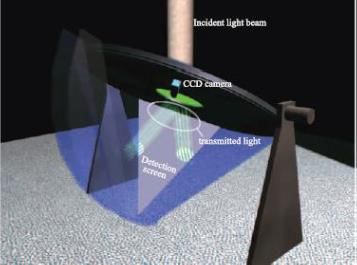
BSDF generation
 procedures for
 daylighting systems

 White paper

 Authors:
 David Geisler-Moroder, Eleanor S. Lee, Gregory Ward,
 Bruno Bueno, Lars O. Grobe, Taoning Wang,
 Bertrand Deroisy, Helen Rose Wilson

 2021-01-20
 T61.C.2.1 – A Technical Report of Subtask C
 DOI: 10.18777/ieashc-task61-2021-0001

 The contents of this report do not necessarily reflect the viewpoints or policies of the International Energy
 Agency (IEA) or its member countries, the IEA Solar Heating and Cooling Technology Collaboration
 Programme (SHC TCP) members or the participating researchers.

 Cover image left: © Bartenbach GmbH, cover image right: © Peter Bartenbach

Page 3

Integrated Solutions for Daylighting and Electric Lighting – Subtask C Report T61.C.2.1 – BSDF generation for daylighting systems
AUTHORS (in alphabetical order)

Bruno BUENO Eleanor S. LEE
Fraunhofer Institute for Solar Energy Systems Lawrence Berkeley National Laboratory
Heidenhofstr. 2, 1 Cyclotron Road
79110 Freiburg i. Br. Berkeley, California 94720
Germany United States of America
bruno.bueno@ise.fraunhofer.de eslee@lbl.gov

Bertrand DEROISY Taoning WANG
Belgian Building Research Institute Lawrence Berkeley National Laboratory
Avenue P. Holoffe 21 1 Cyclotron Road
1342 Limelette Berkeley, California 94720
Belgium United States of America
bertrand.deroisy@bbri.be taoningwang@lbl.gov

David GEISLER-MORODER Greg WARD
Bartenbach GmbH Anyhere Software
Rinner Strasse 14 950 Creston Rd.
6071 Aldrans Berkeley, California 94708
Austria United States of America
david.geisler-moroder@bartenbach.com gregoryjward@gmail.com

Lars Oliver GROBE Helen Rose WILSON
Lucerne University of Applied Sciences and Fraunhofer Institute for Solar Energy Systems
Arts Heidenhofstr. 2,
Technikumstrasse 21 79110 Freiburg i. Br.
6048 Horw Germany
Switzerland helen.rose.wilson@ise.fraunhofer.de
larsoliver.grobe@hslu.ch

 Page 4
KEYWORDS
Bidirectional scattering distribution function (BSDF), daylight system characterization, daylighting,
complex fenestration systems, daylight performance metrics.

ACKNOWLEDGEMENTS
The authors thank their respective funding agencies for supporting their work:

 − The work of Fraunhofer ISE was supported by a Fraunhofer ICON Grant.
 − BBRI received funding from Vlaio (Flanders) through the project VIS IV lntelligente
 lichtregelsystemen (H8C.2017.0932).
 − The work at Bartenbach GmbH was supported by the Federal Ministry for Climate Action,
 Environment, Energy, Mobility, Innovation and Technology (BMK) through the IEA Research
 Cooperation program managed by the Austrian Research Promotion Agency FFG (project
 864136).
 − Research at Lucerne University of Applied Sciences and Arts was supported by the Swiss
 Innovation Agency Innosuisse, grant number 1155000149, as part of the Swiss Competence
 Center for Energy Research SCCER FEEB&D.
 − The work at LBNL and Anyhere Software was supported by the Assistant Secretary for Energy
 Efficiency and Renewable Energy, Building Technologies Office of the U.S. Department of
 Energy under Contract No. DE-AC02-05CH11231, and by the California Energy Commission
 under the Electric Program Investment Charge (EPIC) Program, Solicitation Number: PON-13-
 301, entitled “Developing A Portfolio of Advanced Efficiency Solutions: Technologies and
 Approaches for More Affordable and Comfortable Buildings”.

Page 5

Integrated Solutions for Daylighting and Electric Lighting – Subtask C Report T61.C.2.1 – BSDF generation for daylighting systems
PREFACE
Lighting accounts for approximately 15% of the global electric energy consumption and 5% of
greenhouse gas emissions. Growing economies, higher user demands for quality lighting and rebound
effects as a result of low priced and more versatile electric lighting continuously still lead to an
absolute increase of lighting energy consumption. More light is used, often less consciously.

Especially the electric lighting market but as well the façade, daylighting und building automation
sectors have seen significant technological developments in the past decade. However, these sectors
still act mainly independent of each other, leaving out big potentials lying in a better technology and
market integration. This integration is on the one hand beneficial to providing better user-centred
lighting of indoor spaces. On the other hand, it can contribute significantly to the reduction of
worldwide electricity consumptions and CO2-emissions, which is in line with several different
governmental energy efficiency and sustainability targets.
IEA SHC Task 61 / EBC Annex 77 “Integrated Solutions for Daylighting and Electric Lighting – From
component to system efficiency” therefore pursues the goal to support and foster the better integration
of electric lighting and daylighting systems including lighting controls with a main focus on the non-
residential sector. This includes the following activities:

 − Review relation between user perspective (needs/acceptance) and energy in the emerging
 age of “smart and connected lighting” for a relevant repertory of buildings.
 − Consolidate findings in use cases and “personas” reflecting the behaviour of typical users.
 − Based on a review of specifications concerning lighting quality, non-visual effects as well as
 ease of design, installation and use, provision of recommendations for energy regulations and
 building performance certificates.
 − Assess and increase robustness of integrated daylight and electric lighting approaches
 technically, ecologically and economically.
 − Demonstrate and verify or reject concepts in lab studies and real use cases based on
 performance validation protocols.
 − Develop integral photometric, user comfort and energy rating models (spectral, hourly) as pre-
 normative work linked to relevant bodies: CIE, CEN, ISO. Initialize standardization.
 − Provide decision and design guidelines incorporating virtual reality sessions. Integrate
 approaches into widespread lighting design software.
 − Combine competencies: Bring companies from electric lighting and façade together in
 workshops and specific projects. Hereby support allocation of added value of integrated
 solutions in the market.

To achieve this goal, the work plan of IEA SHC Task 61 / EBC Annex 77 is organized according to the
following four main subtasks, which are interconnected by a joint working group:

 − Subtask A: User perspective and requirements
 − Subtask B: Integration and optimization of daylight and electric lighting
 − Subtask C: Design support for practitioners (Tools, Standards, Guidelines)
 − Subtask D: Lab and field study performance tracking
 − Joint Working Group: Evaluation tool & VR Decision Guide

 Page 6
EXECUTIVE SUMMARY
This white paper summarizes the current state of the art in the field of measurement and simulation
characterization of daylighting systems by bidirectional scattering distribution functions (BSDFs) and
provides recommendations broken down by classes of systems and use cases. It is the result of
collaborative work conducted by members of the IEA SHC Task 61 / EBC Annex 77, Subtask C2. The
document describes proposed procedures for:

 − measuring angle-dependent transmittance and reflectance properties of daylighting and
 shading systems, and
 − generating tabular BSDF data sets from these measurement data for use as input to
 simulation tools.

The type of systems considered in this context include transparent systems, homogeneous or small
pattern diffusing systems, diffuse or specular blinds and grids, macroscopic prismatic systems, and
micro- or nano-structured systems. A complex fenestration system generally consists of a base
material (“curtain”) to modify thermal and visual transmittance of the building envelope, and auxiliary
elements such as mechanical fixing, lateral guides, and control systems. The procedures to determine
the scattering properties described in this document apply to a representative central area of the
façade system without edge effects.
After an introduction, a description of the scope of the white paper, relevant definitions and a
description of commonly used BSDF data resolutions, we describe empirically-based procedures for
generating BSDF data sets for façade systems for later use in lighting simulation software. The overall
procedure differs for microscopic and macroscopic systems and is therefore divided into these two
areas. As different systems require different BSDF data resolutions for different applications, we
provide tabulated recommendations for adequate characterization methods and BSDF resolutions for
different classes of systems. The classes are clustered according to the optical properties of the
systems and according to the resulting requirements for data resolutions. The document closes with a
discussion section on still open issues in BSDF characterization of daylighting systems and their
application in lighting simulation tools.

Page 7

Integrated Solutions for Daylighting and Electric Lighting – Subtask C Report T61.C.2.1 – BSDF generation for daylighting systems
Contents
Contents ................................................................................................................................................................. 8
Nomenclature....................................................................................................................................................... 10
1 Introduction .................................................................................................................................................. 12
2 BSDF definitions .......................................................................................................................................... 13
3 Scope............................................................................................................................................................. 14
4 BSDF resolution ........................................................................................................................................... 15
 4.1 BSDF angular bases ................................................................................................................................ 15
 4.1.1 Klems basis ..................................................................................................................................... 15
 4.1.2 IEA21 basis...................................................................................................................................... 16
 4.1.3 McNeil basis .................................................................................................................................... 16
 4.1.4 Shirley-Chiu, Tensor tree basis........................................................................................................ 17
 4.1.5 Overview .......................................................................................................................................... 17
 4.2 BSDF file format ....................................................................................................................................... 18
 4.2.1 WINDOW XML file format ................................................................................................................ 19
 4.2.2 Extensions available in Radiance .................................................................................................... 19
5 Proposed BSDF generation procedures .................................................................................................... 20
 5.1 BSDF generation procedure for macroscopic systems............................................................................. 21
 5.1.1 Step 1: Characterization of the base material .................................................................................. 21
 5.1.2 Step 2: Set-up of a 3D geometry model of the window attachment ................................................. 21
 5.1.3 Step 3: Simulation of a tabulated BSDF in the desired resolution using a virtual goniophotometer
 (optical software). ........................................................................................................................................... 21
 5.1.4 Step 4: Validation of direct-hemispherical transmission values ....................................................... 21
 5.1.5 Step 5 (optional): Preparation of proxy geometry for inclusion in BSDF XML file ............................ 22
 5.2 BSDF generation procedure for microscopic systems .............................................................................. 22
 5.2.1 Step 1: Goniophotometer measurements ........................................................................................ 22
 5.2.2 Step 2: Fitting a four-dimensional interpolant .................................................................................. 24
 5.2.3 Step 3: Sampling the interpolant model to derive a tabulated BSDF in the desired resolution ........ 25
 5.2.4 Step 4: Validation of direct-hemispherical transmission values ....................................................... 25
 5.3 BSDF generation procedure for microscopic systems: Simplified method for isotropic, non-reflective
 materials ............................................................................................................................................................ 25
 5.3.1 Step 1: Integrating sphere measurements ....................................................................................... 25
 5.3.2 Step 2: Calculate normal-normal transmittance ............................................................................... 26
 5.3.3 Step 3: Create a Radiance BRTDfunc model .................................................................................. 26
 5.3.4 Step 4: Simulation of a tabulated BSDF in the desired resolution using a virtual goniophotometer
 (optical software) ............................................................................................................................................ 26
 5.3.5 Step 5: Validation of direct-hemispherical transmission values ....................................................... 26
 5.3.6 Step 6 (optional): Use the BRTDfunc model as proxy geometry in the simulations ......................... 27
6 Proposed characterization types for various kinds of daylight systems ................................................ 27
 6.1 Transparent systems ................................................................................................................................ 28
 6.2 Homogeneous or small pattern diffusing systems .................................................................................... 29

 Page 8
6.3 Diffuse blinds or grids ............................................................................................................................... 30
 6.4 Specular blinds or grids ............................................................................................................................ 31
 6.5 Macroscopic prismatic systems ................................................................................................................ 32
 6.6 Micro-/Nano-structured systems ............................................................................................................... 33
7 Discussion .................................................................................................................................................... 34
 7.1 Intended uses of BSDF data .................................................................................................................... 34
 7.2 Analytical models ..................................................................................................................................... 34
 7.3 Measurement quality ................................................................................................................................ 34
 7.4 Measurement limitations........................................................................................................................... 35
 7.5 Qualifying or certifying BSDF data ........................................................................................................... 35
 7.6 Meta information in BSDF files ................................................................................................................. 36
 7.7 Limitations of geometrical models ............................................................................................................ 37
 7.8 Special considerations for glare evaluations ............................................................................................ 37
8 References .................................................................................................................................................... 38

Page 9

Integrated Solutions for Daylighting and Electric Lighting – Subtask C Report T61.C.2.1 – BSDF generation for daylighting systems
Nomenclature
 3PM The three-phase method (3PM) [Ward 2011] extends the DC method by
 splitting the flux transfer from the sky dome via the facade to the interior in a
 three-phase matrix calculation. It thereby facilitates modelling of complex
 and dynamic facade systems.

 5PM The five-phase method (5PM) [McNeil 2013] further extends the 3PM
 through a separate calculation of the direct solar contribution and thus
 improves the accuracy of the direct contribution [Lee 2018].

 Analytical BSDF BSDF model described by an analytical function (e.g., Phong, Blinn, Cook-
 model Torrance, Ashikmin-Shirley, Ward-Geisler-Moroder-Dür, Harvey-Shack, …)

 BRDF Bidirectional Reflectance Distribution Function

 BSDF Bidirectional Scattering Distribution Function

 BTDF Bidirectional Transmittance Distribution Function

 DC method The Daylight Coefficient (DC) method [Bourgeois 2009] is a calculation
 method that is based on relative contributions from discretized sky patches
 to lighting quantities at (interior) positions. It allows efficient annual daylight
 calculations.

 DGP The Daylight Glare Probability metric [Wienold and Christoffersen 2006] is
 calculated by processing a luminance map of the field of view. It considers
 that discomfort glare can be caused by two different effects: (1) a saturation
 effect caused by big glare sources (e.g., a window), and (2) a contrast effect
 produced by peaky glare sources [Wienold et al. 2019].

 eDGPs The Enhanced Simplified DGP (eDGPs) [Wienold, 2009] is a
 computationally efficient alternative to the DGP in which the saturation term
 is calculated as proportional to the vertical eye illuminance and the contrast
 term is calculated through a simplified image of the field of view. This
 simplified image neglects the ambient bounces of light rays, but it has been
 shown to preserve the relevant information required by the contrast effect.
 Different methods can be used to calculate the vertical illuminance and the
 simplified image (e.g., [Abravesh 2019]).

 High-resolution Tabulated BSDF with basis discretization using hemisphere subdivisions
 BSDF with average patch sizes covering solid angles corresponding approximately
 to cones with opening angles smaller than 10°.

 Low-resolution Tabulated BSDF with basis discretization using hemisphere subdivisions
 BSDF with average patch sizes covering solid angles corresponding approximately
 to cones with full opening angles of about 10° to 24°.

Macroscopic system A daylighting or shading system that cannot be directly measured with
 currently available goniophotometers (i.e., cannot measure a representative
 area of the system (e.g., venetian blinds, honeycomb blinds, fabrics with

 Page 10
arbitrary patterns or surfaces with irregular perforations)). The illuminated
 area and transmittance sample aperture should have linear dimensions that
 are several times larger (at least a factor of five or better yet ten) than the
 linear dimensions of inhomogeneity of the sample. For example, with an
 illuminating beam of 30 mm cross-section, the linear dimension of the
 repeating period should not be larger than 6 mm, better 3 mm.

 Microscopic system A daylight system that can be directly measured with a gonio-photometer,
 i.e., that has a structure where the scattering properties can be
 characterized correctly from a representative area of the system (e.g., roller
 shade fabric, microstructured prismatic film).

 Peak extraction Algorithm to identify peaks in the undistorted direct-through direction of a
 tabulated BSDF. Based on this, the “vision” component and the unscattered
 directly transmitted solar component can be separated in the simulation. For
 example, in Radiance the algorithm is implemented in the “aBSDF” material
 type [Ward 2018].

 Tabulated BSDF BSDF model described by a discrete set of values for a defined number and
 set of directions (i.e., tabulated values of the function)

 Variable-resolution BSDF with high spatial resolution in the peaky areas of the distribution and
 BSDF reduced resolution in smooth areas with approximately diffuse behavior
 [Ward 2014].

 Page 11
IEA SHC Task 61 / EBC Annex 77: Integrated Solutions for Daylighting and Electric Lighting
1 Introduction
This white paper is the result of collaborative work conducted by members of the International Energy
Agency (IEA) Solar Heating and Cooling (SHC) Programme Task 61 [IEA 2020], Subtask C2. The
white paper describes proposed procedures for:
 1) measuring angle-dependent transmittance and reflectance properties of daylighting and
 shading systems, and then
 2) generating bidirectional scattering distribution functions (BSDF) from the measured data for
 use as input to simulation tools.

The type of systems considered in this document include for example roller blinds, venetian blinds,
louvres, prismatic films, and patterned or fritted glazing. A shading system generally consists of a base
material (“curtain”, [CEN 2018]) provided to modify characteristics such as thermal, visual
transmittance of the building envelope, and auxiliary elements such as mechanical fixing, lateral
guides, and control systems. The procedures to determine the scattering properties described in this
document apply to a representative central area of the façade system without edge effects.

Procedures differ depending on the type of system and intended use of the BSDF data. Output from
simulation tools include illuminance and luminance data for the assessment of daylight availability,
lighting energy use, visual comfort, indoor environmental quality, and other visual and non-visual
performance parameters related to daylight from windows and skylights. Output also includes
transmitted solar irradiance which can enable more detailed analysis of thermal comfort and solar
loads on indoor surfaces.

The white paper is intended to stimulate discussion and critical review of these procedures internally
within the IEA task and then also externally by research and industry. More detailed technical
procedures will then be developed by the IEA SHC Task 61 C2 sub-committee from this and other
reference sources with the end objective of releasing harmonized procedures to be considered by
international standards organizations.

For some classes of products, the described procedures in this document are not intended to be used
for each unique variant of the product on the market (e.g., every color of a type of weave of shade
fabric). Instead, the procedures are intended to generate a gold standard, empirically based BSDF
dataset from which alternate analytical BSDF models could be derived. As an example, an analytical
model was developed from spectrophotometer data for solar heat gain simulations of fabrics [Kotey
2009]. Methods for deriving such analytical BSDF models are not included in this document. The
procedures also do not include descriptions of how material sample(s) should be obtained in order to
adequately represent variations in manufacturing (e.g., required number and selection of samples).
Other outstanding technical and procedural issues are raised in the Discussion section for further
internal and external review and discussion.

 Page 12
2 BSDF definitions
This section provides a summary of fundamental concepts and term definitions related to BSDFs. For
more detailed background information, see [Nicodemus 1977, Lewis 1994].

A bidirectional scattering distribution function (BSDF) f(θ1, ϕ1; θ2, ϕ2) describes the scattering
properties of a material by specifying the amount of radiance incident from direction (θ 1, ϕ1) that is
reflected and/or transmitted in the exiting direction (θ2, ϕ2) (see Figure 1), i.e., the overall radiance
exiting in direction (θ2, ϕ2) is given as:
 2
 2 ( 2 , 2 ) = ∫0 ∫0 1 ( 1 , 1 ) ( 1 , 1 ; 2 , 2 ) | 1 | 1 1 1 (1)

 Figure 1. Polar and azimuthal angles of incident and exiting directions. Source: LBNL.

A physically plausible BSDF exhibits three properties:
 1. Positivity:
 ( 1 , 1 ; 2 , 2 ) ≥ 0 (2)
 2. Helmholtz reciprocity:
 ( 1 , 1 ; 2 , 2 ) = ( 2 , 2 ; 1 , 1 ) (3)
 3. Energy conservation:
 2
 ( 1 , 1 ) = ∫0 ∫0 ( 1 , 1 ; 2 , 2 ) | 2 | 2 2 2 ≤ 1 ( 1 , 1 ) (4)

 i.e., the overall reflected and transmitted energy is bounded by 1.
This BSDF definition in four dimensions (two for the incident direction and two for the exiting direction)
implicitly assumes spectral uniformity and insensitivity to polarization at least for two broadband
spectral ranges (visible with wavelengths from about 380 nm to 780 nm and solar from 280 nm to
4000 nm). For typical window attachments in combination with uncoated glazing units, the angular
differences in spectral reflection or transmission behavior for finer spectral ranges is negligible, thus
this assumption is legitimate in this context. The assumptions need to be re-examined for the
combination with coated glazing units. Spectral characterization for analysis of the non-visual effects
of lighting and daylighting for atypical materials may be addressed in future work.

 Page 13
IEA SHC Task 61 / EBC Annex 77: Integrated Solutions for Daylighting and Electric Lighting
BSDFs contain information about transmission and reflection properties, BTDF and BRDF,
respectively. The direct-hemispherical transmission for an incident direction (θ 1, ϕ1) is given by:
 2 /2
 ( 1 , 1 ) = ∫0 ∫0 ( 1 , 1 ; 2 , 2 ) 2 2 2 2 (5)

Analytical BSDF models are widely used in computer graphics. As examples, a clear glazing or an
ideal mirror are described by Dirac delta functions defining the transmittance or reflectance for the
direct transmitted or mirrored direction, respectively, and zero elsewhere. Common models for
scattering include the Phong model [Phong 1975], Blinn model [Blinn 1977], Cook-Torrance model
[Cook 1981], Ashikmin-Shirley model [Ashikhmin 2000], Ward-Geisler-Moroder-Dür model [Geisler-
Moroder 2010], and generalized Harvey-Shack model [Krywonos 2011]. These analytical models are
widely used for generic material descriptions in simulations, but their assumptions must be reviewed if
applied to façade systems different from those initially considered by the models.

In the present context, we are talking about tabulated BSDFs. Here the function
f(θ1, ϕ1; θ2, ϕ2) is specified via a discrete set of values for a defined number and set of directions (θ1,
ϕ1; θ2, ϕ2), described as incident and exiting patches (patchi, patche). Typical resolutions are described
later in Section 0.

The direct-hemispherical transmission for radiation incident from a patch i is thus given as:
 ( ℎ ) = ∑ =1 ( ℎ , ℎ ) (6)

where n is the number of patches describing the exiting hemisphere and is the projected solid angle
of ℎ .

3 Scope
The proposed procedures are intended to be used to characterize the light-scattering properties of a
single layer, planar window attachment, i.e., an attachment that can be represented as a thin flat
surface with analogous light-scattering properties (layer model). This includes systems like clear or
translucent glazing, fabrics, films, or blinds. The resulting BSDF is independent of the intended
method of installation – interior, exterior (coplanar, or parallel to the window, or non-coplanar, as an
overhang or fin), or in the gap of a double- or triple-glazed window. A BSDF for a multi-layer system
can be computed from multiple BSDFs in special cases where there is no interdependence between
the scattering properties of the single layers. This for example excludes systems where the repeating
patterns or “periods” for each attachment layer are the same, e.g., two layers of venetian blinds offset
by a half period. To combine attachment BSDFs with additional glazing layers, [WINDOW 2020]
enables this calculation with Klems resolution. For variable and high resolution BSDF data, a method
for the computational combination has been proposed in [Grobe 2017].

We group window attachment products into two categories – “microscopic” and “macroscopic”. This
classification has no definition in absolute geometrical dimensions, rather it indicates if a sample of the
product can be measured with a goniophotometer directly or if its periodical structure is too large to be
correctly captured with such a measurement device. As an example, a scanning goniophotometer with
an incident light beam diameter at the sample plane of 30 mm can be used to directly measure
systems like fabrics with typical periodical structures of a few millimeters or less. In contrast, a
venetian blind system with 60-mm-wide slats spaced 40 mm apart cannot be measured with such an
instrument.

 Page 14
4 BSDF resolution
Tabulated BSDFs are specified via a discrete set of values for a defined number and set of directions
(θ1, ϕ1; θ2, ϕ2). As an example, they can be generated from discrete measured BSDF data and using
an interpolation model [Ward et al. 2014]. The resolution of measured- and tabulated BSDF data
needs to match the optical properties of the represented system and the respective application. For
example, a prismatic, daylight-redirecting film with pronounced peaks in the scattering distribution
requires significantly higher resolution BSDF data than a nearly-Lambertian, translucent panel.
Likewise, the calculation of daylight autonomy, which is based on hourly illuminance readings over the
year, is less critically dependent on high-resolution BSDF data than the calculation of luminance-
based metrics, such as discomfort glare.

For the remainder of this document, we use the nomenclature low-resolution BSDF and high-
resolution BSDF to refer to tabulated BSDFs as follows:

 ● BSDF resolutions based on hemisphere subdivisions with average patch sizes covering solid
 angles corresponding approximately to cones with full opening angles of about 10° to 24° are
 referred to as low-resolution BSDFs.
 Examples: Klems, Tregenza, McNeil, Tensor tree with basis resolution 256 patches (=2 8).
 ● BSDF resolutions with average patch sizes covering solid angles corresponding approximately
 to cones with full opening angles of smaller than 10° are described as high-resolution BSDFs.
 Examples: Tensor tree with basis resolution 1024 patches (=210) or more.

4.1 BSDF angular bases
Various angular bases for tabulated BSDFs have been defined for various building energy simulation
purposes.

4.1.1 Klems basis
The Klems 145x145 subdivision of the incident and exiting hemispheres was initially proposed for
solar heat gain calculations [Klems 1994]. See Figure 2.

 Figure 2. Klems BSDF angular basis [Klems 1994] for incident / exiting hemispheres.

 Page 15
IEA SHC Task 61 / EBC Annex 77: Integrated Solutions for Daylighting and Electric Lighting
4.1.2 IEA21 basis
Based on the recommended practice for measuring daylight by the Commission Internationale de
l'Éclairage [CIE 1994], the International Energy Agency (IEA) SHC Task 21 [IEA 1999] proposed a
BSDF angular basis based on incident directions similar to Tregenza’s subdivision of the hemisphere
and an equidistant angular subdivision in the exiting direction. A common implementation of this
format uses 5° steps in both θ and ϕ angles in the exiting direction (Figure 3).

 Figure 3. IEA21 BSDF angular basis [IEA 1999] for incident (left) and exiting (right) hemispheres.

4.1.3 McNeil basis
A modified version of the Klems basis was proposed in [McNeil et al., 2017] to provide a clear division
between upward and downward flux for daylight-redirecting systems (Figure 4). This enables
independent evaluation of the efficiency of redirection above the horizon (exiting flux in the upward
direction at low grazing angles being most efficient for core daylighting) versus potential visual
discomfort from downward transmitted flux below the horizon.

 Figure 4. McNeil BSDF angular basis [McNeil et al. 2017] for incident / exiting hemispheres.

 Page 16
4.1.4 Shirley-Chiu, Tensor tree basis
To enable a high-resolution representation of peaky areas in the exiting direction while keeping the
overall data set reasonably small, [Ward et al., 2014] developed a variable-resolution BSDF
representation (Figure 5). The general subdivision of the hemisphere is based on “a low distortion map
between disk and square” [Shirley 1997], where neighboring areas with similar BSDF values (i.e.,
nearly diffuse behavior) are averaged to a single entry.

Figure 5. Example Shirley Chiu / Tensor tree angular basis [Ward et al., 2014] with basis resolution of 4096 patches, i.e.,
 212 (left) and example exiting variable resolution hemisphere for specular glass (right).

4.1.5 Overview
The BSDFViewer software [McNeil 2013] can be used to display BSDF data in a falsecolor plot given
either in Klems resolution or in Shirley-Chiu / Tensor tree resolution. Other possibilities to view BSDF
data are provided e.g., by [Ladybug Tools 2020] and [LightTools 2020]. Table 1 summarizes current
BSDF data formats and corresponding total number of subdivisions for the incident and exiting
hemispheres.
Table 2 gives an overview of software tools currently available that can use BSDF data and which
formats they support.

Table 1. Angular bases for tabulated BSDFs and number of subdivisions per incident and exiting hemispheres.

 BSDF angular basis Incident hemisphere Exiting hemisphere

 Klems 145 (Klems) 145 (Klems)

 IEA21 145 (Tregenza) 1297 (5° full, i.e., 5° x 5°)

 McNeil 146 (Klems modified) 146 (Klems modified)

 Shirley-Chiu, Tensor Tree variable basis resolution = 22n variable basis resolution = 22n
 (typical n = 4, 5, or 6, i.e., 256, (typical n = 4, 5, or 6, i.e., 256,
 1024, or 4096 subdivisions) 1024, or 4096 subdivisions)

 Page 17
IEA SHC Task 61 / EBC Annex 77: Integrated Solutions for Daylighting and Electric Lighting
Table 2. Angular bases for tabulated BSDFs used by simulation software.

 BSDF angular basis Software handling this basis (list not claiming to be exhaustive)

 Klems WINDOW, Radiance, Relux, Honeybee, DIVA4Rhino, Fener, DALEC,
 LightStanza, COMFEN, IDA ICE, SPOT Pro, OpenStudio

 IEA21 DIALux, Relux

 McNeil - * (Radiance with a modified genBSDF script [McNeil 2017])

 Shirley-Chiu, Tensor Radiance, Honeybee, DIVA4Rhino, LightStanza
 Tree

4.2 BSDF file format
Currently, [WINDOW 2020] enables generation of BSDF data with the Klems format. Within the
Radiance BSDF library, the Klems and Shirley-Chiu / Tensor tree BSDF formats are supported and
can be generated with the genBSDF tool. For alternate bases such as IEA21 or McNeil, Radiance’s
genBSDF program can be adapted to produce a tabulated BSDF file in these formats.

Note that conventions for phi and theta and the definition of front and back surfaces of the shading or
daylighting system differ between goniophotometers, Radiance [Ward 2011, Radsite 2020b], and
WINDOW [Curcija et al. 2018]). For anisotropic systems with different scattering properties between
front and back surfaces (e.g., a daylight redirecting system with a clear zenith orientation and outdoor
facing surface), ensuring that these conventions are clearly documented and aligned at each step
when generating a BSDF is far more critical than for isotropic samples with the same properties on
both sides of the system (e.g., translucent panel). The Radiance pabopto2bsdf script (see Section 5.2
Step 2) uses the convention suggested for a specific scanning goniophotometer [pab 2020]. When
using genBSDF, the Radiance convention must be followed [Radsite 2020b]. Both bsdf2klems and
bsdf2ttree convert from the Radiance convention to the WINDOW convention for the XML file, which is
then converted back to the Radiance convention during rendering.

 Page 18
4.2.1 WINDOW XML file format
We propose to follow the XML file format described in Section 6.4. of the WINDOW 6.1 / THERM 6.1
Research Version User Manual [Mitchell 2006]. This template specifies the “Layer” as a container
holding three elements: “Material”, “DataDefinition” and “WavelengthData”.

As part of the “DataDefinition”, the WINDOW specification for the Klems BSDF resolution is defined as
“IncidentDataStructure” Columns and the “AngleBasis” with the “AngleBasisName” LBNL/Klems Full.
Scattering data are provided in four 145x145 matrices for the four components: “Transmission Front”,
“Transmission Back”, “Reflection Front” and “Reflection Back”. With the WINDOW XML file format, the
convention has been established that “front” is assumed to face outdoors, “back” indoors. The
following designations are used:

 Incident hemisphere Exiting hemisphere
 Transmission front Outdoors Indoors
 Reflection front Outdoors Outdoors
 Transmission back Indoors Outdoors
 Reflection back Indoors Indoors

4.2.2 Extensions available in Radiance
To enable definition of high-resolution BSDF data in the XML scheme, [Ward 2011] extended the XML
structure by adding the “IncidentDataStructure” types TensorTree3

for isotropic BSDF data and TensorTree4 for anisotropic BSDF data. The corresponding “AngleBasis”
is defined as LBNL/Shirley-Chiu. The scattering data is provided in nested lists with curly braces to
specify the nodes of the tensor tree.

To include proxy geometry in the BSDF file, a further element “Geometry” has been defined. The
current implementation in Radiance interprets geometry in the MGF format [Ward 1996] which is
specified in the XML files as:

 Geometry description in MGF format

With this extension, proxy geometry can be included with the BSDF data set to enable improved
calculations of the direct solar contribution (see Step 5 in Section 5.1).

Additional tags to the data will be needed to document the measurement conditions and analytical
models from which the tabulated BSDF data were derived. This desired metadata is discussed in
Section 7.

 Page 19
IEA SHC Task 61 / EBC Annex 77: Integrated Solutions for Daylighting and Electric Lighting
5 Proposed BSDF generation procedures
We describe empirically-based procedures for generating BSDF data sets for façade systems for
subsequent use in lighting simulation software. The overall procedure differs for microscopic and
macroscopic systems. A simplified procedure for generating BSDFs for microscopic systems with
rotational symmetry is also given.

For macroscopic systems, the procedure consists of four main steps and one optional step for
including system geometry:
 1. Characterize the base material using fundamental data (e.g., index of refraction, diffuse
 reflectance) or BSDF data generated for microscopic systems using the procedure above).
 2. Set-up a three-dimensional geometric model of the window attachment; then,
 3. Use simulations to produce a tabulated BSDF in the desired resolution using a virtual
 goniophotometer (optical ray-tracing software).
 4. Validate the direct-hemispherical transmission values.
 1. (optional): Prepare proxy geometry for inclusion in the BSDF XML file.

For microscopic systems, the procedure consists of four steps:
 2. Take goniophotometer measurements of exiting transmittance and reflectance for selected
 incident directions.
 3. Compute a four-dimensional interpolant from the measured data.
 4. Sample the interpolant to derive a tabulated BSDF in the desired resolution.
 5. Validate the direct-hemispherical transmission values.

For microscopic systems with rotational symmetry without highlights (e.g., isotropic fabrics, with
or without a direct, through component (openness), but without light redirection) and for which the
optical transmittance can be approximated by a specular/diffuse split, an alternate procedure is as
follows:
 1. Take integrating sphere measurements of normal-hemispherical and normal-diffuse
 transmittance and reflectance, and cut-off angle. Ensure that the angular range excluded from
 “normal-diffuse” is well-defined (see e.g., NFRC 300 or EN 14500:2020 [CEN 2020]).
 2. Calculate normal-normal transmittance by subtracting the normal-diffuse transmittance from
 the normal-hemispherical transmittance.
 3. Forge a Radiance BRTDfunc model as described in [Wienold et al. 2017]. This model takes as
 input parameters the normal-normal and normal-diffuse transmittance, the normal-
 hemispherical reflectance, and the cut-off angle of the fabric.
 4. Use simulations to produce a tabulated BSDF in the desired resolution using a virtual
 goniophotometer (optical ray-tracing software).
 5. Validate the direct-hemispherical transmission values.
 6. (optional): Use the BRTDfunc model as proxy geometry in the simulations.

 Page 20
5.1 BSDF generation procedure for macroscopic systems

5.1.1 Step 1: Characterization of the base material
The material characterization is either provided by the manufacturer either as BRDF/BTDF data or as
parameters for parametric models such as ABg or Gaussian, which e.g. are used in optical design
software. For refractive systems, the index of refraction, absorption coefficients, and parameters for
volume scattering (if relevant) are provided.
If the necessary data or analytical model parameters are not provided by the manufacturer, the
material properties are measured using a goniophotometer following the BSDF generation procedure
for microscopic systems (see Section 5.2). The resulting data are either fitted to parametric models
(Section 5.2, Steps 1 and 2) or converted into a tabulated BSDF (Section 5.2, Steps 1 to 3) for further
use in simulation tools.

5.1.2 Step 2: Set-up of a 3D geometry model of the window attachment
A three-dimensional (3D) geometrical model of the window attachment needs to be prepared in a
computer-aided design (CAD) system for import into lighting simulation software. The geometric model
must encompass a large area of the system so that a representative area of the system in the center
of the CAD model can be extracted. One should define an area where the rays are spawned, and this
area should encompass an integer number of periodic features of the system. Taking venetian blinds
as an example, a periodic feature would be a blind and a gap. This area should also be small enough
compared to the entire system geometry. In this way, edge effects can be avoided and a generic
BSDF for the system can be generated. General limitations and restrictions of geometrical models are
discussed later in Section 0.

5.1.3 Step 3: Simulation of a tabulated BSDF in the desired resolution using a
virtual goniophotometer (optical software).
The material model (analytical or tabulated BSDF) from Step 1 is applied in the simulation software to
the 3D geometry prepared in Step 2. Using optical simulation software, the BSDF of the system is
then generated by mimicking a goniophotometer setup (infinite plane of material). For the desired
resolution of the final BSDF, all incident-to-exiting patch relations are evaluated. A uniform light
distribution over each single patch of incident directions is used to illuminate the sample and the
resulting exiting distribution is evaluated through integration over the single exiting patch directions.

The Radiance software includes a virtual goniophotometer tool called genBSDF. This utility can be
used to generate BSDF data of virtual 3D models in low resolution (Klems basis) and in high
resolution (tensor tree with variable resolution). Validation of genBSDF was completed by [McNeil et
al. 2013].

5.1.4 Step 4: Validation of direct-hemispherical transmission values
As for microscopic systems (compare Step 4 in Section 5.2) also for macroscopic systems the direct-
hemispherical transmission values are validated through integrating sphere measurements. Therefore,
the illuminated area and transmittance sample aperture must have linear dimensions that are several
times larger (at least a factor of five, or better ten) than the linear dimensions of inhomogeneity. This
ensures that the geometric modelling and simulation adequately represent the properties of the
system in terms of overall transmitted light flux. Again, to have a valid BSDF, the relative difference of
τd-h, i, BSDF from τd-h, i, ref should be less than 10%, the relative difference of τh-h, BSDF from τh-h, ref should be
no more than 5%.

 Page 21
IEA SHC Task 61 / EBC Annex 77: Integrated Solutions for Daylighting and Electric Lighting
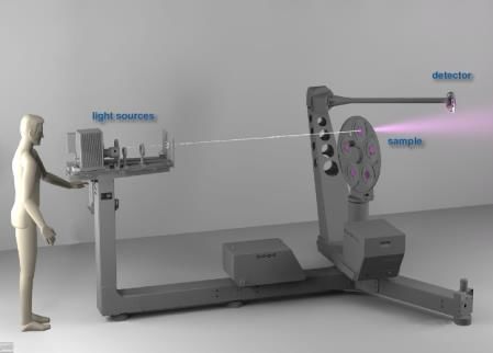
5.1.5 Step 5 (optional): Preparation of proxy geometry for inclusion in BSDF
XML file
As described in Section 4.2, geometry information of the daylight system can be included in the BSDF
XML file. The geometry can be used in simulations as a proxy for the BSDF description of the daylight
system in the shadow testing algorithm. As an example, for venetian blinds, this enables the rendering
of shadow patterns instead of an averaged, extenuated light patch inside the room. With this, the
direct solar contribution to interior light levels can be calculated with greater accuracy. Additionally,
proxy geometry provides a correct appearance of the system in the facade.

The provision of exact system geometry could be prohibited because of intellectual property (IP)
protections. Thus, it might be useful to adapt or simplify the geometry in a way that the resulting proxy
does not disclose protected knowledge, while still producing approximately correct shadow patterns
and appearance.

5.2 BSDF generation procedure for microscopic systems

5.2.1 Step 1: Goniophotometer measurements
In the first step, measurements are taken of a flat sample with a goniophotometer for selected
incident directions. Depending on the symmetry of the sample, 9, 45, 81 or 145 incident directions
(assuming the Klems basis) may need to be measured for systems with rotational, quadrilateral,
bilateral, or no symmetry, respectively. Table 3 lists the θ and φ angles associated with these incident
directions. Measurement of a subset of these incident directions may be sufficient, resulting in a
minimal loss of accuracy. However, further sensitivity analysis is needed to understand the effects on
error for each system. An example sensitivity analysis is given in [Lee et al. 2018]. Further discussion
on measurement directions and limitations can be found in Section 7.4.

In the exiting directions, measurement requirements for angular resolution depends on the type of
shading or daylighting material. For materials that do not exhibit specular or semi-specular
transmission or reflection, for example, high-resolution angular measurements in the exiting
hemisphere may not be necessary. For materials that do exhibit specular or peaky distributions with
transmission or reflection, high resolution measurements are needed. For the latter, the
goniophotometer must be able to take high angular resolution measurements to capture the shape of
the peaks and be accurate within a broad dynamic range (e.g., angular resolution of better than 0.04°,
step size of 0.01°, and contrast of greater than 1:20,000 [Schwanengel 2010]).

BSDF system characterizations and goniophotometer measurements are undertaken at various
institutions worldwide. Within the IEA SHC Task 61 / EBC Annex 77 “Integrated Solutions for
Daylighting and Electric Lighting”, international experts reviewed and documented currently used
measurement methods [IEA 2020] (Figure 6). In [IEA, 1999] prior measurement methods are
described. These procedures have been co-developed and vetted amongst a handful of institutions
under prior IEA Tasks 21 and 50 and related research projects (e.g., BIM-SOL [Grobe 2018a]). A
discussion on broadening industry’s measurement capabilities is given in Section 7.

 Page 22
Table 3. Proposed incident directions for goniophotometric measurements.

 Number of incident Number of incident
 Symmetry Symmetry
 directions directions
 Rotational (isotropic) 9 Quadrilateral 45
 Incident directions Incident directions
 θ [°] φ [°] θ [°] φ [°] θ [°] φ [°] θ [°] φ [°]

 0 0 0 0
 50 0 50 0-90 every 15
 10 0 10 0-90 every 45
 60 0 60 0-90 every 15
 20 0 20 0-90 every 22.5
 70 0 70 0-90 every 22.5
 30 0 30 0-90 every 18
 82.5 0 82.5 0-90 every 30
 40 0 40 0-90 every 15

 Number of incident Number of incident
 Symmetry Symmetry
 directions directions
 Bilateral 81 None (anisotropic) 145
 Incident directions Incident directions
 θ [°] φ [°] θ [°] φ [°] θ [°] φ [°] θ [°] φ [°]

 0 0 0 0
 50 0-180 every 15 50 0-345 every 15
 10 0-180 every 45 10 0-315 every 45
 60 0-180 every 15 60 0-345 every 15
 20 0-180 every 22.5 20 0-337.5 ev. 22.5
 70 0-180 every 22.5 70 0-337.5 ev. 22.5
 30 0-180 every 18 30 0-342 every 18
 82.5 0-180 every 30 82.5 0-330 every 30
 40 0-180 every 15 40 0-345 every 15

 Page 23
IEA SHC Task 61 / EBC Annex 77: Integrated Solutions for Daylighting and Electric Lighting
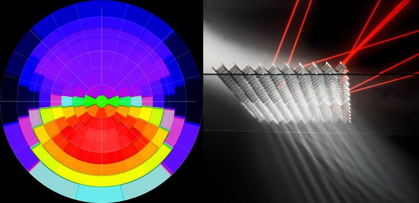
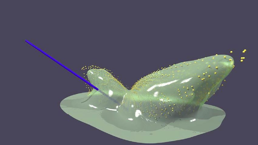
Figure 6. Examples of goniophotometer measurement setups: left: pab Ltd Gonio-Photometer II; center: Lighttec Reflet
 180S; right: LESO-PB / EPFL video-goniophotometer. Sources: [pab 2020], [Light Tec 2020], [Andersen 2005].

5.2.2 Step 2: Fitting a four-dimensional interpolant
For the selected incident directions in Step 1, we have a point cloud of data in the exiting direction with
corresponding BSDF values. For further use in simulations, a full four-dimensional description of the
BSDF is required. This can be achieved by fitting parameters of an analytical scattering model to the
data (e.g., the Ashikhmin-Shirley model or the Ward-Geisler-Moroder-Dür model, see Section 2). This
however limits the possible shapes to the scope of the models and often yields faulty results.
For this step, the proposed method is to generate an interpolant model for the measured incident
directions based on a fit to the measured exiting distribution using Gaussian radial basis functions
(RBF) [Ward 2014]. In the Radiance BSDF library, this fitting is done by the tool pabopto2bsdf
[Radsite 2020a]. This model is still sparse on the incident hemisphere, but includes information
needed to interpolate properly in all four dimensions.

Figure 7. Fitting of an interpolant RBF model (green) to a set of measured values (yellow points), log scale. Source: G.
 Ward [Lee 2018].

 Page 24
5.2.3 Step 3: Sampling the interpolant model to derive a tabulated BSDF in the
desired resolution
The Gaussian RBF model from Step 2 is then transformed into the desired resolution of a tabulated
BSDF. To obtain a full hemispherical distribution, the incident directions must be interpolated. To avoid
erroneous peak positions through linear interpolation, a mass transport algorithm must also be
applied.

Integrating the RBF model over the related solid angle areas using Monte Carlo methods, the
particular incident-to-exiting patch relations are obtained. This method is also applied in the relevant
tools in the Radiance BSDF library. bsdf2klems generates low-resolution BSDF data sets based on
the Klems angular basis, while bsdf2ttree is used to convert the BSDF into a variable-resolution data
set based on tensor trees [Ward et al. 2014].

If the BSDF data of the microscopic system is later used for a simulation-based generation of BSDF
data for a macroscopic system (Step 1 in Section 5.1), care must be taken to choose a resolution that
covers the material’s relevant properties. If e.g., a Klems resolution is used to represent a high
specular aluminum material, no reasonable high-resolution tensor tree BSDF of a blind system made
of this material can be generated. The low-resolution base material would already misrepresent any
reflection off the slat.

5.2.4 Step 4: Validation of direct-hemispherical transmission values
Direct-hemispherical transmission and reflectance values are measured using a nearly parallel light
beam (e.g., sunlight outdoors or indoors via redirecting mirrors or an artificial light beam (“artificial
sun”)) and an integrating sphere. To capture relevant structures in the resulting distributions, a
resolution of at least 5° for both polar and azimuthal angles is proposed for the incident directions,
preferably a resolution of 1° is used. Bilinear interpolation is used to generate a full hemispherical
distribution. Multiple measurements of different areas of the sample can be made to characterize
errors associated with variability in manufacturing.
The resulting distribution from the integrating sphere is integrated over the incident patch areas of the
generated BSDF to obtain an average direct-hemispherical transmission τd-h, i, ref for each incident
patch i. From the BSDF data set the same average direct-hemispherical transmission τd-h, i, BSDF for
each incident patch i is calculated by integration over the exiting distribution in the BSDF.

To have a valid BSDF, the relative difference of τd-h, i, BSDF from τd-h, i, ref should be less than 10%
(referring to error limits of DIN class B luxmeters [DIN 2017, Gossen 2019] and findings from [IEA
1999]).

The hemispherical-hemispherical transmission values τh-h, ref and τh-h, BSDF, are derived through
integration over all incident patches from τd-h, i, ref and τd-h, i, BSDF, respectively. The relative difference of
τh-h, BSDF from τh-h, ref should be no more than 5%.

5.3 BSDF generation procedure for microscopic systems:
 Simplified method for isotropic, non-reflective materials

5.3.1 Step 1: Integrating sphere measurements
The following brief set of best practices for integrating sphere measurements are based on research
work in preparation for the revised version of EN 14500, which should come into effect in 2020 [CEN
2020]. In multi-purpose integrating spheres intended for use together with high-end laboratory
benchtop spectrophotometers, it is important that the internal surface of the integrating sphere be as
homogeneous as possible, i.e. the ratio of sample and detector aperture areas should be small (< 0.1)
compared to the total sphere area and the white material used as reflection references and to close
apertures should be similar in scattering distribution and spectrum to the white material coating the
sphere interior.

 Page 25
IEA SHC Task 61 / EBC Annex 77: Integrated Solutions for Daylighting and Electric Lighting
You can also read