VWR INSTRUCTION MANUAL - Stereomicroscope - VWR International
←
→
Page content transcription
If your browser does not render page correctly, please read the page content below
VWR
Stereomicroscope			         series 300

                  INSTRUCTION MANUAL

                  Model                  European Catalogue Number
                 SZB350                           630-1578
                 SZT350                           630-1580
                SZB350 OH                         630-1583
                SZT350 OH                         630-1584

Version:   3
Issued:    19, 05, 2014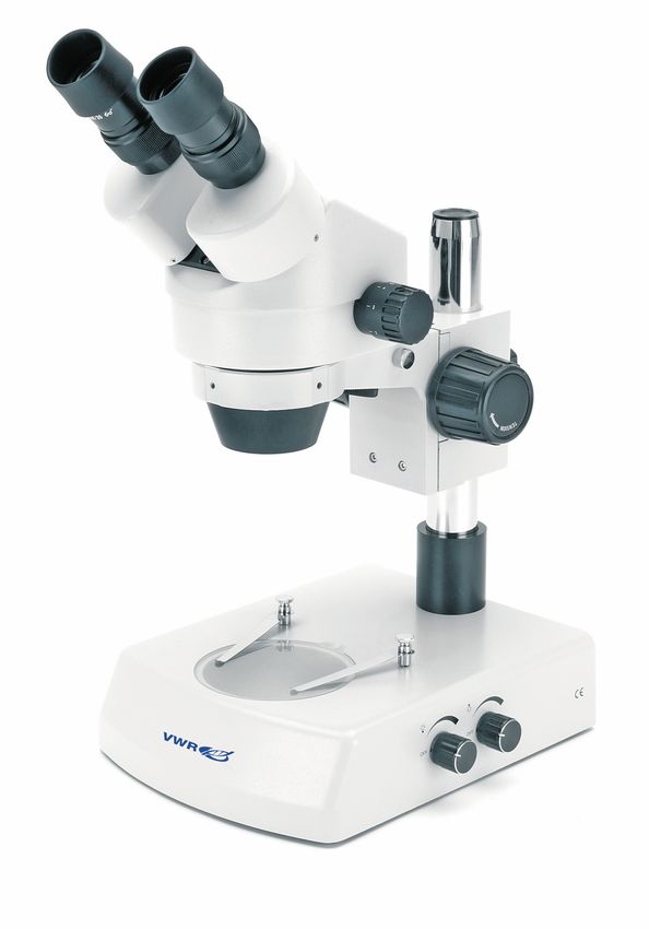
Legal Address of Manufacturer

Europe
VWR International bvba
Researchpark Haasrode 2020
Geldenaaksebaan 464
B-3001 Leuven
+ 32 16 385011
http://be.vwr.com

Country of origin: ITALY

                                 Table of Contents

Warning
Safety information
Package Contents
Unpacking
Intended Use
Symbols and conventions
Specifications
Instructions for use
      Overview
      Description of Buttons and Switches
      Operation
Troubleshooting
Repair and maintenance
Accessories and spares
Technical Service
Warranty
Compliance with local laws and regulations
Disposal

                                       2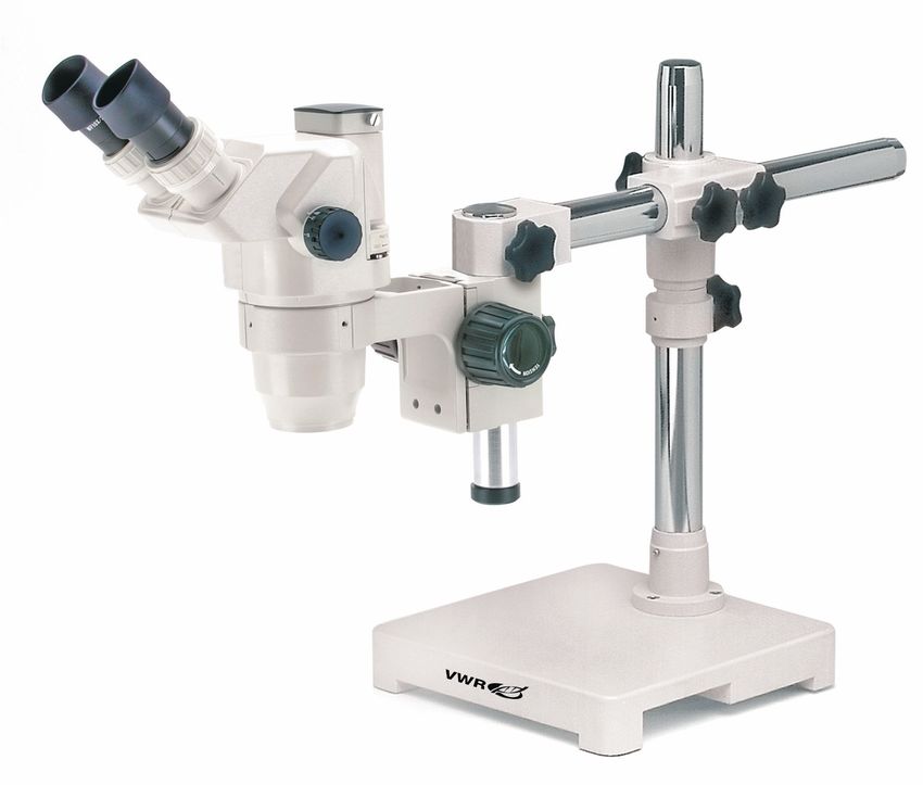
Warning
This microscope is a scientific precision instrument designed to last for many years with a minimum of main-
tenance. It is built to high optical and mechanical standards and to withstand daily use.
We remind you that this manual contains important information on safety and maintenance, and that it must
therefore be made accessible to the instrument users.
We decline any responsibility deriving from incorrect instrument use that does not comply with this manual.

Safety Information

       Avoiding Electrical Shock

Before plugging in the power supply, make sure that the supplying voltage of your region matches with the
operation voltage of the equipment and that the lamp switch is in off-position.

Users should observe all safety regulations of the region. The equipment has acquired the CE safety label.
However, users do have full responsibility to use this equipment safely.
Please follow the guidelines below, and read this manual in its entirety to ensure safe operation of the unit.

Package Contents

DESCRIPTION                                                               QUANTITY

Microscope stand with focus and illuminators (NO illumination             1
on -OH versions)
Optical stereo head                                                       1
Eyepiece WF10x/20mm                                                       2
Disc for transmitted illumination (NOT included in -OH versions) 1
Dust cover                                                                1

Unpacking
The microscope is housed in a moulded Styrofoam container. Remove the tape from the edge of the contai-
ner and lift the top half of the container. Take some care to avoid that the optical items (head and eyepieces)
fall out and get damaged. Using both hands (one around the arm and one around the base), lift the microsco-
pe from the container and put it on a stable desk.

Place the observation head onto the top of the arm and tighten the lock-screw. Insert the eyepieces into the
eye tubes.

Connect the provided power supply cable to the input socket on the rear of the microscope.

                                                           3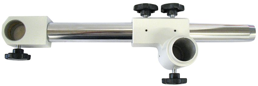
Overhanging stand assembling
- Screw the main long pole into the thread on the base.

- Slide the stop-ring along the pole, and fix it with a provided screw.

- Prepare the horizontal rod, with 4 screws.

                                                   4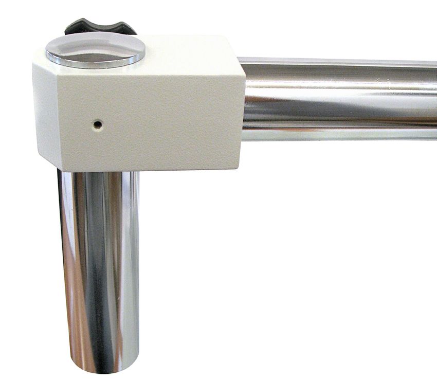
- Then slide the rod along the main pole. Make it rest on the stop-ring, it will provide additional safety, avoiding
  that the microscope could hit the sample.

- At the end of the horizontal arm, slide the short rod in.

- Take the focus, and mount it on the short rod. At the bottom of the rod, screw the fixing cap.

                                                              5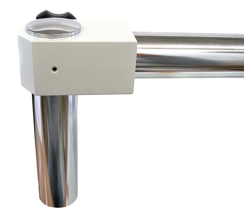
- Finally, mount the stereomicroscope head into the focus, and lock the head with the provided screw.

          Intended use
          For research use only. Not intended for any animal or human therapeutic or diagnostic use.

          Symbols and conventions
          The following chart is an illustrated glossary of the symbols that are used in this manual.

                                            CAUTION
                                            This symbol Indicates a potential risk and alerts you to proceed with
                                            caution

          PRODUCT SPECIFICATIONS

  Model           Head         Eyepieces       Objectives        Working         Stand                        Illumination
                                                                 Distance

 SZB350         Binocular    EWF 10x/20mm   0,7 .... 4,5x Zoom   100 mm        Pillar stand     Incident and transmitted 12V/15W halogen

 SZT350         Trinocular   EWF 10x/20mm   0,7 .... 4,5x Zoom   100 mm        Pillar stand     Incident and transmitted 12V/15W halogen

SZB350 OH       Binocular    EWF 10x/20mm   0,7 .... 4,5x Zoom   100 mm     Overhanging stand                     ---

SZT350 OH       Trinocular   EWF 10x/20mm   0,7 .... 4,5x Zoom   100 mm     Overhanging stand                     ---

                                                                  6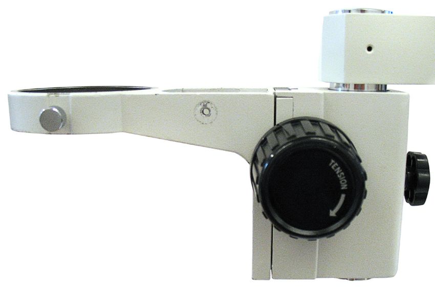
OVERVIEW
                       EYEPIECE

                                      STEREO HEAD

                                              ZOOM KNOB

                                                    FOCUSING KNOB

DIOPTRIC ADJUSTMENT
RING

           OBJECTIVE

       STAGE PLATE
                                          BRIGHTNESS ADJUSTMENT
                                          KNOB

                                  7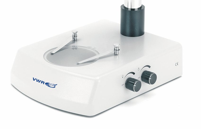
Overhanging stand version (-OH)
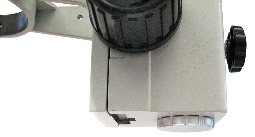
DESCRIPTION OF BUTTONS AND SWITCHES
Front View
INCIDENT
ILLUMINATION
CONTROL
TRANSMITTED
ILLUMINATION
CONTROL
8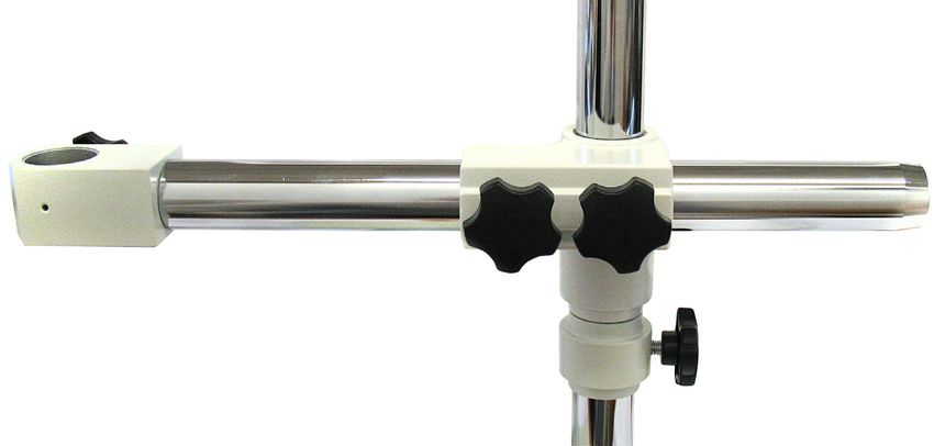
Operation
Illumination system
These microscopes come with an integrated illumination system with incident and transmitted light. For the
microscopes without integrated illumination systems it is possible to use an external cold light source. By
using the correct light is possible obtain the better image of your sample.
Before starting, read the section about electrical safety precautions. Then, insert the power cord and use the
brightness controls to turn on the lamps and control the light intensity.
The base is equipped with two clips that can be used to block the specimen.

Adjust interpupillary distance
Hold the right and left parts of the observation head by both hands and adjust the interpupillary distan¬ce by
moving the two parts until one circle of light can be seen. If two circles appear, the interpupillary distance is
too big, and if two overlapped circles appear, the interpupillary distance is too small.

Focus and regulation of the focusing tension
Put the sample to be observed on the plate and turn the zoom to the highest magnification using the bilateral
zoom knob. Try to focus the sample using the focusing knobs.

Dioptric compensation
This compensation makes it possible for people with glasses to adjust the microscope to their eyes and use
the microscope without glasses. Turn the zoom down to the lowest magnification. Adjust the diopter com-
pensation ring of the right eyepiece tube until the image of the right eyepiece is clear and sharp. Repeat the
procedure for the left eyepiece. Then, check the focus of the image for the whole zoom range. It should now
be perfectly parfocal (focus is always maintained during the change of magnification).

Magnification and working distance
The total magnification varies from 1.75x to 180x depending on the eyepieces and auxiliary objectives used.
With the bilateral zoom knob, the user can change the magnification in a factor of 6.4 with perfect parfocality
and the image is always centred.
Select the desired magnification by adjusting the bilateral zoom knob. Change the eyepieces and/or add an
appropriate magnifying objective lens if necessary. The total magnification used can be calculated by the
following equation:
Total magnification = Eyepiece magnification x Zoom magnification x Objective lens magnification
Normal working distance for the standard configuration (1x objective lens) is 95 mm.

Video capturing (optional)
Two kinds of observation heads, binocular or trinocular, are available for the series. They can all be con-
nected to cameras via an adaptor, for digital and analogical photo and video capturing.
Before taking a picture or filming video, pull out the light path selector lever so the light will be deflected into
the photo tube. At the same time, no light will enter into the right eyepiece tube for observation. Please refer
to the adaptor and camera manuals for further details.

                                                              9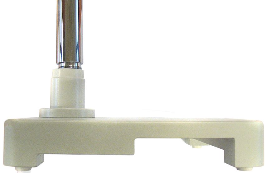
Troubleshooting
Review the information in the table below to troubleshoot operating problems.

 PROBLEM                                 CAUSE                             SOLUTION

 LIGHT DOESN’T TURN ON                   Power supply not plugged.         Check that the power supply cable is
                                                                           well inserted on the rear of the micro-
                                                                           scope.
                                         Potentiometer                     Rotate the brightness adjustment
                                                                           potentiometers and check if there is an
                                                                           increase in the light output.
 IMAGE CANNOT BE SEEN OR                 Optical head out of focus         Change the height of the head until you
 IS DARK.                                                                  reach the correct focus.
                                         Brightness level is low           Rotate the brightness adjustment po-
                                                                           tentiometers.
                                         Photo tube inserted               If not using a camera, check that
                                                                           the path selection lever is fully
                                                                           inserted into the head (photo output
                                                                           disabled).
 IMAGE IS UNCLEAR, BLURRED Objectives or filters are dirty. Wipe them clean.
 OR HAS INSUFFICIENT       Optical head out of focus        Change the height of the head until you
 CONTRAST.                                                  reach the correct focus.
                           Eyepieces set incorrectly Check the eypieces are set to “zero”
                                                            position of dioptric compensation (rota-
                                                            ting the ring below each eyepiece).

Repair and maintenance
Microscopy environment
This microscope is recommended to be used in a clean, dry and shock free environment with a temperature
of 0-40°C and a maximum relative humidity of 85 % (non condensing). Use a dehumidifier if needed.

        To think about when and after using the microscope

The microscope should always be kept vertically when moving it and be careful so that no moving parts, such
as the eyepieces, fall out. Never mishandle or impose unnecessary force on the microscope.
Never attempt to service the microscope yourself.
After use, turn off the light immediately, cover the microscope with the included dust-cover, and keep it in a
dry and clean place.

        Electrical safety precautions

Before plugging in the power supply, make sure that the supplying voltage of your region matches with the
operation voltage of the equipment and that the lamp switch is in off-position.
Users should observe all safety regulations of the region. The equipment has acquired the CE safety label.
However, users do have full responsibility to use this equipment safely.

Cleaning the optics
If the optical parts need to be cleaned try first to: use compressed air. If that is not sufficient: use a soft lint-free
piece of cloth with water and a mild detergent. And as a final option: use the piece of cloth moistened with a
3:7 mixture of ethanol and ether. Note: ethanol and ether are highly flammable liquids. Do not use them near
a heat source, near sparks or near electric equipment. Use these chemicals in a well ventilated room.

                                                      10
Remember to never wipe the surface of any optical items with your hands. Fingerprints can damage the op-
tics. Do not disassemble objectives or eyepieces in attempt to clean them.
For the best results, use the VWR cleaning kit (see catalog number below).
If you need to send the microscope to manufacturer for maintenance, please use the original packa-
ging.
User replaceable accessories and spare parts
DESCRIPTION QUANTITY CAT. NO.
Eyepieces WF10x/20 mm 2 630-1779
Eyepieces WF15x/15 mm 2 630-1780
Eyepieces WF20x/10 mm 2 630-1781
Eyepiece micrometric WF10x/20 mm 1 630-1782
Additional lens 0,5x (w.d. 165 mm) 1 630-1783
Additional lens 0,75x (w.d. 117 mm) 1 630-1784
Additional lens 1,5x (w.d. 47 mm) 1 630-1786
Additional lens 2x (w.d. 26 mm) 1 630-1786
Polarising set (filters and rotating stage) 1 630-1787
Darkfield condenser 1 630-1788
Sample clip 1 630-1789
Moving stage 1 630-1790
Reflex camera adapter for full frame sensor 1 630-1791
CCD camera adapter (for 1/3” sensors) 1 630-1792
CCD camera adapter (for 1/2” sensors) 1 630-1793
Eye cups type 2 2 630-1794
White/black object-plate, type 2 dia. 95 mm 1 630-1795
Glass stage, type 2, dia. 95 mm 1 630-1796
Halogen bulb, 12V/15W 1 630-1797
Halogen bulb, 12V/15W, with dichroic mirror 1 630-1798
Dust cover type 13 1 630-1799
Heating stage, with digital temperature controller 1 630-1800
APS-C Reflex camera adapter 1 630-1801
Cleaning kit 1 630-1803
11Technical service
Web Resources
Visit the VWR’s website at www.vwr.com for:
• Complete technical service contact information
• Access to VWR’s Online Catalogue, and information about accessories and related products
• Additional product information and special offers
Contact us For information or technical assistance contact your local VWR representative or visit. www.
vwr.com.
Warranty
VWR International warrants that this product will be free from defects in material and workmanship for a
period of five (5) years from date of delivery. If a defect is present, VWR will, at its option and cost, repair,
replace, or refund the purchase price of this product to the customer, provided it is returned during the war-
ranty period. This warranty does not apply if the product has been damaged by accident, abuse, misuse, or
misapplication, or from ordinary wear and tear. If the required maintenance and inspection services are not
performed according to the manuals and any local regulations, such warranty turns invalid, except to the ex-
tent, the defect of the product is not due to such non-performance.
Items being returned must be insured by the customer against possible damage or loss. This warranty shall
be limited to the aforementioned remedies. IT IS EXPRESSLY AGREED THAT THIS WARRANTY WILL BE
IN LIEU OF ALL WARRANTIES OF FITNESS AND IN LIEU OF THE WARRANTY OF MERCHANTABILITY.
Compliance with local laws and regulations
The customer is responsible for applying for and obtaining the necessary regulatory approvals or other au-
thorizations necessary to run or use the Product in its local environment. VWR will not be held liable for any
related omission or for not obtaining the required approval or authorization, unless any refusal is due to a
defect of the product.
12Disposal
This equipment is marked with the crossed out wheeled bin symbol to indicate that this equipment must not
be disposed of with unsorted waste.
Instead it is your responsibility to correctly dispose of your equipment the end of its life cycle by handling it
over to an authorized facility for separate collection and recycling. It is also your responsibility to decontami-
nate the equipment in case of biological, chemical and/or radiological contamination, so as to protect from
health hazards the persons involved in the disposal and recycling of the equipment.
For more information about where you can drop off your waste equipment, please contact your local dealer
from whom you originally purchased this equipment.
By doing so, you will help to conserve natural and environmental resources and you will ensure that your
equipment is recycled in a manner that protects human health.
Thank you
13Australia Hungary Singapore
VWR International, Pty Ltd. VWR International Kft. VWR Singapore Pte Ltd
Unit 1/31 Archimedes Place Simon László u. 4. 18 Gul Drive
Murarrie, Queensland 4172 4034 Debrecen Singapore 629468
Tel.: 1300 727 696 Tel.: (52) 521-130 Tel.: +65 6505 0760
Fax: 1300 135 123 Fax: (52) 470-069 Fax: +65 6264 3780
E-mail: info@hu.vwr.com E-mail: sales@sg.vwr.com
Austria
VWR International GmbH India
Graumanngasse 7 VWR Lab Products Private Limited Spain
1150 Vienna 135/12, Brigade Towers, 2nd Floor VWR International Eurolab S.L.
Tel.: +43 1 97 002 0 Front wing, Brigade Road, C/ Tecnología 5-17
Fax: +43 1 97 002 600 Bengaluru, India – 560 025 A-7 Llinars Park
E-mail: info@at.vwr.com Tel.: +91-80-41117125/26 (Bengaluru) 08450 - Llinars del Vallès
Tel.: +91-2522-647911/922 (Mumbai) Barcelona
Belgium Fax: +91-80-41117120 Tel.: 902 222 897
VWR International bvba E-mail: vwr_india@vwr.com Fax: 902 430 657
Researchpark Haasrode 2020 E-mail: info@es.vwr.com
Geldenaaksebaan 464 Ireland / Northern Ireland
3001 Leuven VWR International Ltd / Sweden
Tel.: 016 385 011 VWR International (Northern Ireland) Ltd VWR International AB
Fax: 016 385 385 Orion Business Campus Fagerstagatan 18a
E-mail: customerservice@be.vwr.com Northwest Business Park 163 94 Stockholm
Ballycoolin Tel.: 08 621 34 00
China Dublin 15 Fax: 08 621 34 66
VWR International China Co., Ltd Tel.: 01 88 22 222 E-mail: kundservice@se.vwr.com
Rm.219, 2100 Dongming Road Fax: 01 88 22 333
Pudong New District E-mail: sales@ie.vwr.com Switzerland
Shanghai 200123 VWR International GmbH
Tel.: +86-21-5898 6888 Italy Lerzenstrasse 16/18
Fax: +86-21-5855 8801 VWR International PBI S.r.l. 8953 Dietikon
E-mail: info_china@vwr.com Via San Giusto 85 Tel.: 044 745 13 13
20153 Milano (MI) Fax: 044 745 13 10
Czech Republic Tel.: 02-3320311/02-487791 E-mail: info@ch.vwr.com
VWR International s. r. o. Fax: 800 152999/02-40090010
Veetee Business Park E-mail: info@it.vwr.com Turkey
Pražská 442 Pro Lab Laboratuar Teknolojileri Ltd.Şti.
CZ - 281 67 Stříbrná Skalice The Netherlands a VWR International Company
Tel.: +420 321 570 321 VWR International B.V. Orta Mah. Cemal Gürsel Caddesi
Fax: +420 321 570 320 Postbus 8198 Ördekcioglu Işmerkezi No.32/1
E-mail: info@cz.vwr.com 1005 AD Amsterdam 34896 Pendik - Istanbul
Tel.: 020 4808 400 Tel.: +90216 598 2900
Denmark Fax: 020 4808 480 Fax: +90216 598 2907
VWR - Bie & Berntsen E-mail: info@nl.vwr.com Email: info@pro-lab.com.tr
Transformervej 8
2730 Herlev New Zealand UK
Tel.: 43 86 87 88 Global Science - A VWR Company VWR International Ltd
Fax: 43 86 87 90 241 Bush Road Customer Service Centre
E-mail: info@dk.vwr.com Albany 0632, Auckland Hunter Boulevard - Magna Park
Tel.: 0800 734 100 Lutterworth
Finland Fax: 0800 999 002 Leicestershire
VWR International Oy E-mail: sales@globalscience.co.nz LE17 4XN
Valimotie 9 Tel.: 0800 22 33 44
00380 Helsinki Norway Fax: 01455 55 85 86
Tel.: 09 80 45 51 VWR International AS E-mail: uksales@uk.vwr.com
Fax: 09 80 45 52 00 Haavard Martinsens vei 30
E-mail: info@fi.vwr.com 0978 Oslo
Tel.: 02290
France Fax: 815 00 940
VWR International S.A.S. E-mail: info@no.vwr.com
Le Périgares – Bâtiment B GO TO VWR.COM FOR THE
201, rue Carnot Poland LATEST NEWS, SPECIAL OFFERS
94126 Fontenay-sous-Bois cedex VWR International Sp. z o.o.
Tel.: 0 825 02 30 30 (0,15 € TTC/min) Limbowa 5 AND DETAILS OF YOUR LOCAL
Fax: 0 825 02 30 35 (0,15 € TTC/min) 80-175 Gdansk VWR DISTRIBUTOR
E-mail: info@fr.vwr.com Tel.: 058 32 38 200 do 204
Fax. 058 32 38 205
Germany E-mail: info@pl.vwr.com
VWR International GmbH
Hilpertstraße 20a Portugal
D - 64295 Darmstadt VWR International -
Freecall: 0800 702 00 07 Material de Laboratório, Lda
Fax: 0180 570 22 22* Edifício Neopark
Email: info@de.vwr.com Av. Tomás Ribeiro, 43- 3 D
*0,14 €/Min. aus d. dt. Festnetz 2790-221 Carnaxide
Tel.: 21 3600 770
Fax: 21 3600 798/9
E-mail: info@pt.vwr.com
14VWR
Stereomicroscope series 300
MANUEL D’UTILISATION
Modèle European Catalogue Number
SZB350 630-1578
SZT350 630-1580
SZB350 OH 630-1583
SZT350 OH 630-1584
Version: 3
du: 19, 05, 2014Adresse du Fabricant
Europe
VWR International bvba
Researchpark Haasrode 2020
Geldenaaksebaan 464
B-3001 Leuven
+ 32 16 385011
http://be.vwr.com
Pays d’origine: ITALIE
Contenu
Avertissement
Précautions
Contenu de l’emballage
Deballage
Usage
Symboles et conventions
Caractéristiques techniques
Instructions pour l’utilisation
Description
Intérrupteurs et jacks
Utilisation
Résolution de problèmes
Réparation et entretien
Accessoires et pièces de rechange
Assistance technique
Garantie
Conformité à la législation et aux réglementations locales
Ramassage
16Avertissement
Le présent microscope est un appareil scientifique de précision créé pour offrir une durrée de vie de plusieurs
années avec un niveau d’entretient mininum. Les meilleurs composants optiques et mécaniques ont été uti-
lisés pour sa conception ce qui fond de lui un appareil idéal pour une utilisation journalière.
Ce guide contient des informations importantes sur la sécurité et l’entretien du produit et par conséquent il
doit être accessible à tous ceux qui utilisent cet insrument.
Toute responsabilité dérivant d’une utilisation inappropriée du présent instrument non contemplée dans ce
guide d’utilisation est décliné.
Précautions
Précautions de sécurité sur le système électrique
Avant de connecter le câble d’alimentation au réseau électrique assurez vous que la tension d’entrée soit
compatible avec celle de l’appareil et que l’interrupteur de l’éclairage soit en position arrêt.
L’utilisateur devra consulter les normes de sécurités de son pays. L’appareil inclu une étiquette de sécurité
C.E. Dans tous les cas, l’utilisateur assume toute responsabilité relative à l’utilisation sûre de l’appareil.
Suivre les directives ci-dessous et lire ce manuel dans son intégralité pour un fonctionnement sûr de l’instru-
ment.
Contenu de l’emballage
DESCRIPTION QUANTITÉ
Statif avec mise au point et éclairage (non inclus avec les 1
versions-OH)
Tête stéréo 1
Oculaire (WF)10x/20mm 2
Disque pour éclairage transmis (non inclus avec les versions- 1
OH)
Housse anti-poussière 1
DEBALLAGE
Le microscope est livré dans un emballage en polystyrène. Après avoir enlevé le papier adhésif de l’emballa-
ge, enlevez la partie supérieure de l’emballage. Faites attention à ce que les composants optiques (objectifs
et oculaires) ne tombent pas ou ne s’endommagent pas. Sortez le microscope de son emballage et posez le
sur une superficie stable et plate.
Fixez la tête d’observation sur la partie supérieure du corps du microscope en utilisant les vis de fixation cor-
respondantes. Introduisez l’oculaire dans le porte oculaire.
Branchez le câble d’alimentation (fourni) à l’arrière du microscope.
17Assemblage du support surplombant
- Visser le pôle principal long dans le fil sur la base.
- Glisser la bague de retenue le long du pôle et la fixer avec la vis fournie.
- Préparer la tige horizontale, avec 4 vis.
18- Ensuite, glisser la tige le long du pôle principal. Faites-la reposer sur la bague de retenue, cela la rendra
encore plus sûre et évitera que le microscope heurte l’échantillon.
- Au bout du bras horizontal, faites glisser la tige courte à l’intérieur.
- Prendre le dispositif de mise au point et le monter sur la tige courte. Au bout de la tige, visser le capuchon
de fixation.
19- Enfin, monter la tête du stéréo-microscope sur le dispositif de mise au point, et bloquer la tête avec les vis
fournies.
Usage
Uniquement pour la recherche. Non destiné à usage thérapeutique ou diagnostique sur animaux ou êtres
humains.
Symboles et conventions
Le tableau suivant est un glossaire illustré des symboles qui sont utilisés dans ce manuel.
ATTENTION
Ce symbole indique un risque potentiel et vous avertit de procéder
avec prudence
CARACTÉRISTIQUES TECHNIQUES
Modèle Tête Oculaire(s) Objectifs Distance de Platine Eclairage
travail
Eclairage halogène 12V/15W transmis et
SZB350 Binoculaire EWF 10x/20mm 0,7 .... 4,5x Zoom 100 mm Base à colonne
incident
Eclairage halogène 12V/15W transmis et
SZT350 Trinoculaire EWF 10x/20mm 0,7 .... 4,5x Zoom 100 mm Base à colonne
incident
Statif lourd à bras
SZB350 OH Binoculaire EWF 10x/20mm 0,7 .... 4,5x Zoom 100 mm
déporté
---
Statif lourd à bras
SZT350 OH Trinoculaire EWF 10x/20mm 0,7 .... 4,5x Zoom 100 mm
déporté
---
20DESCRIPTION
OCULAIRE
TÊTE STÉRÉO
RÉGLAGE
GROSSISSEMENT
ZOOM
BOUTON DE
COMMANDE MISE AU
POINT
COMPENSATION
DIOPTRIQUE
OBJECTIFS
PLATE-FORME
D’OBSERVATION
RÉGLAGE DE L’INTENSITÉ
LUMINEUSE
21VERSION AVEC STATIF LOURD À BRAS DÉPORTÉ(-OH)
DESCRIPTION DES COMMANDES ET DES INTÉRRUPTEURS
Arrière
ECLAIRAGE INCIDENT
ECLAIRAGE TRANSMIS
22Utilisation
Eclairage
Ces microscopes sont équipés d’un système d’éclairage incident et transmis. Pour les modèles sans éclai-
rage, il est possible d’utiliser un générateur à lumière froide externe. En utilisant l’éclairage correcte il est
possible d’obtenir une meilleure image de l’échantillon.
Avant de commencer, lire le paragraphe consacré aux normes de sécurité électrique.
Ensuite, brancher le câble d’alimentation et utiler les commandes de réglage de la luminosité pour allumer
les éclairages et vérifier l’intensité de la lumière.
La base est equipée de deux valets de fixation pour bloquer l’échantillon.
Réglage de la distance interpupillaire
Agir sur les deux tubes porte-oculaires jusqu’à la vision d’un champ lumineux unique et circulaire. Le fait de
voir deux cercles signifie que la distance interpupillaire est trop grande; par contre l’apparition de deux cer-
cles superposés signifie que la distance interpupillaire est trop petite.
Mise au point et réglage de la tension de la mise au point
Placer un objet à observer sur le plan d’observation et placer le bouton de réglage zoom sur le facteur d’a-
grandissement maximum. Effectuer la mise au point en tournat les commandes appropriées.
Compensation dioptrique
Cette compensation permet aux porteurs de lunettes d’ajuster le microscope de manière à pouvoir l’utiliser
sans lunettes. Déplacer le grossissement du zoom au minimum . Régler la commande de compensation
dioptrique de l’oculaire droit jusqu’à l’obtention d’une image claire et nette dans l’oculaire droit. Répéter
l’opération pour l’oculaire gauche. A ce point contrôler la mise au point de l’image pour chaque intervalle de
grossissement, il devrait résulter parfaitement parafocale (la mise au point est maintenue durant le change-
ment de grossissements).
Grossissement et distance de travail
Le grossissement total varie de 1.75x à 180x et dépend des oculaires et des objectifs auxiliaires utilisés. Avec
le bouton de zoom bilatéral, l’usager peut changer le grossissement de manière parfaitement parafocale tout
en maintenant toujours le centrage de l’image
Sélectionner le grossissement désiré à travers la rotation des commandes de réglage de l’objectif zoom.
Changer les oculaires et/ajouter si nécéssaire une lentille (objectif) de grossissement Le grossissement total
peut être calculé ainsi :
Grossissement total = grossissement des oculaires x grossissement zoom x grossissement lentille objectif.
La distance de travail dans la configuration standard (lentille-objectif 1x) est de 95 mm.
Acquisition photo/vidéo (facultative)
La série est disponible en têtes d’observation binoculaire et trinoculaire. Il est possible de les connecter à une
caméra ou à un appareil photo en utilisant un adaptateur pour la câpture d’image vidéo et pour l’acquisition
de photographies numériques et analogiques.
Pour l’acquisition d’image photo ou de vidéo, tirer avant tout le levier de sélection du parcours lumineux, ainsi
la lumière sera détournée dans le tube photographique. A partir de ce moment précis aucune autre lumière
ne devrait pénétrer dans le tube oculaire d’observation. Pour avoir plus de détails sur les adaptateurs, appa-
reils photo et caméra, consulter les manuels d’instructions
T
23Résolution de problèmes
Consulter les informations ci-dessous pour la résolution de problèmes durant l’utilisation.
PROBLÈME CAUSA SOLUTION
LA LUMIÈRE NE S’ALLUME L’alimentation n’est pas Vérifier que l’alimentation soit branchée
PAS branchée correctement à l’arrière du microscope
Potentiomètre Tourner le potentiomètre de réglage de
la luminosité et vérifier si la luminosité
augmente
L’IMAGE NE SE VOIT PAS OU La tête optique n’est pas au Changer la hauteur de la tête afin
EST TROP SOMBRE point d’obtenir une mise au point correcte
La luminosité est trop faible Tourner le potentiomètre de réglage de
la luminosité
Le levier photo/vidéo n’a pas Si l’utilisation d’un caméra n’est pas
été tiré en cours, vérifier que le levier photo/
vidéo soit complètement à l’intérieur de
la tête
L’IMAGE EST FLOUE, Les objectifs ou les filtres Les nettoyer
TROUBLE OU PRÉSENTE UN sont sales
CONTRASTE INSUFFISANT La tête optique n’est pas au Changer la hauteur de la tête afin
point d’obtenir une mise au point correcte
Oculaires mal réglés Vérifier que les oculaires soit sur la
position “zéro” de la compensation
dioptrique ( régler l’anneau sur chaque
oculaire)
Réparation et entretien
Environnement de travail
Il est conseillé d’utiliser le microscope dans un environnement propre et sec, protégé des impactes, à une
température comprise entre 0°C y 40°C et avec une humidité relative maximale de 85% (en absence de con-
densation). Il est conseillé d’utiliser un déshumidificateur si nécessaire.
Conseils avant et après l’utilisation du microscope.
- Maintenir le microscope toujours en position verticale lorsque vous le déplacez. Assurez vous que les
pièces mobiles (oculaires) ne tombent pas.
- Manipulez avec attention le microscope en évitant de le forcer.
- Ne réparez pas le microscope vous même
- Éteindre immédiatement la lumière après avoir utilisé le microscope, couvrez le avec la housse prévue à cet
effet et conservez le dans un endroit propre et sec.
Précaution de sécurité sur le système électrique
Avant de connecter le câble d’alimentation sur le réseau électrique assurez vous que la tension d’entrée soit
compatible avec celle de l’appareil et que l’interrupteur de l’éclairage soit en position arrêt.
L’utilisateur devra consulter les normes de sécurités de son pays. L’appareil inclu une étiquette de sécurité
C.E. Dans tous les cas, l’utilisateur assume toute responsabilité relative à l’utilisation sûre de l’appareil.
24Nettoyage des optiques
Si vous souhaitez nettoyer les optiques, utilisez dans un premier temps de l’air comprimé. Si cela n’est pas
suffisant, utilisez alors un chiffon non effiloché, humidifié avec un peut d’eau et avec un détergent délicat.
Comme dernière option, il est possible d’utiliser un chiffon humide avec une solution de 3:7 de alcool éthyli-
que et de l’éther.
Attention: l’alcool éthylique et l’éthanol sont des substances hautement inflammables.
Ne les utilisez pas près d’une source de chaleur, d’étincelles ou d’appareils électriques.
Les substances chimiques doivent être utilisées dans un environnement aéré. Ne pas frotter la superficie
d’aucun des composants optiques avec les mains. Les empreintes digitales peuvent endommager les parties
optiques.
Ne démontez pas les objectifs ou les oculaires pour essayer de les nettoyer.
Pour les meilleurs résultats, utiliser le kit de nettoyage (code ci-dessous).
Conserver l’emballage d’origine dans le cas où il serait nécessaire de retourner le microscope au
fournisseur pour un entretien ou une réparation.
Accessoires et pièces de rechanges
DESCRIPTION QUANTITÉ CODE
Oculaires WF10x/20mm 2 630-1779
Oculaires WF15x/15mm 2 630-1780
Oculaires (WF20x/10mm 2 630-1781
Oculaire micrométrique WF10x/20mm 1 630-1782
Lentille additionnelle 0,5x (distance de travail 165 mm) 1 630-1783
Lentille additionnelle 0,75x ( distance de travail 117 mm) 1 630-1784
Lentille additionnelle 1,5x (distance de travail 47 mm) 1 630-1786
Lentille additionnelle 2x ( distance de travail 26 mm) 1 630-1786
Jeu pour lumière polarisée (filtres et platine rotative) 1 630-1787
Condenseur pour fond noir 1 630-1788
Valets 1 630-1789
Platine 1 630-1790
Adaptateur pour appareil photo réflex avec capteur full 1 630-1791
frame
Adaptateur pour caméra CCD (pour capteur 1/3”) 1 630-1792
Adaptateur pour caméra CCD (pour capteur 1/2” ) 1 630-1793
Oeilletons, type n. 2 2 630-1794
Disque noir/blanc de rechange, diamètre 95 mm type 2 1 630-1795
Disque translucide de rechange, diamètre 95 mm type 2 1 630-1796
Ampoule (halogène) 12V/15W 1 630-1797
Ampoule (halogène) 12V/15W avec miroir dichroïque 1 630-1798
Couverture anti-poussière type 13 1 630-1799
Platine chauffante pour stéréomicroscopes avec contrôle 1 630-1800
numérique de la température
Adaptateur pour appareil photo réflex avec capteur APS-C 1 630-1801
Kit de nettoyage 1 630-1803
25Service technique
Ressources Web
Visitez le site Web de VWR à l’adresse www.vwr.com pour:
• Coordonnées complètes du service technique.
• Accès au catalogue en ligne de VWR et à des informations sur les accessoires et produits connexes.
• Informations supplémentaires sur les produits et les offres spéciales.
Contactez-nous Pour plus d’informations ou une assistance technique, contactez votre représentant VWR
local ou visitez le site www.vwr.com.
Garantie
VWR International garantit ce produit pièces et main-d’œuvre pour une durée de cinq (5) ans à compter
de la date de livraison. En cas de vice, VWR pourra, à sa discrétion et à ses frais, réparer, remplacer ou
rembourser au client le prix d’achat du produit, à condition qu’il lui soit retourné au cours de la période de
garantie. Cette garantie n’est pas applicable si le dommage provient d’un accident, d’une utilisation abusive
ou incorrecte, d’une mauvaise application ou de l’usure normale du produit. Cette garantie deviendrait non
valide dans le cas où les services de maintenance et de vérification requis ne seraient pas exécutés confor-
mément aux manuels et réglementations locales, sauf exception si le défaut du produit n’est pas imputable
à cette non exécution.
Il est recommandé au client d’assurer les éléments retournés contre les risques éventuels d’endommagement
ou de perte. Cette garantie se limite aux réparations susmentionnées. IL EST EXPRESSÉMENT CONVENU
QUE LA PRÉSENTE GARANTIE SE SUBSTITUE À TOUTES LES GARANTIES DE CONFORMITÉ ET DE
VALEUR MARCHANDE.
Conformité à la législation et aux réglementations locales
Le client est chargé de la demande et de l’obtention des approbations réglementaires et autres autorisations
nécessaires à l’utilisation ou à l’exploitation du Produit dans l’environnement local. VWR ne saura être tenu
responsable de toute omission ou non obtention des approbations ou autorisations requises, sauf exception
si le refus est dû à un défaut du produit.
26Ramassage
Le symbole du conteneur qui figure sur l’appareil électrique ou sur son emballage indique que le produit de-
vra être, à la fin de sa vie utile, séparé du reste des résidus. Pour la gestion du ramassage sélectif du présent
instrument, l’utilisateur qui souhaite éliminer l’appareil devra se mettre en contact avec le fabricant et suivre
la procédure que celui-ci a adopté pour permettre le ramassage sélectif de l’appareil. Le ramassage sélectif
correct de l’appareil pour son recyclage, traitement et élimination compatible avec l’environnement contribue
à éviter d’éventuels effets négatifs sur l’environnement et la santé et favorise la réutilisation et/ou recyclage
des composants de l’appareil. L’élimination du produit de manière abusive de la part de l’utilisateur entraînera
l’application de sanctions administratives sur la norme en vigueur.
Merci.
27Allemagne Hongrie République Tchèque
VWR International GmbH VWR International Kft. VWR International s. r. o.
Hilpertstraße 20a Simon László u. 4. Veetee Business Park
D - 64295 Darmstadt 4034 Debrecen Pražská 442
Freecall: 0800 702 00 07 Tel.: (52) 521-130 CZ - 281 67 Stříbrná Skalice
Fax: 0180 570 22 22* Fax: (52) 470-069 Tel.: +420 321 570 321
Email: info@de.vwr.com E-mail: info@hu.vwr.com Fax: +420 321 570 320
*0,14 €/Min. aus d. dt. Festnetz E-mail: info@cz.vwr.com
Inde
Australie VWR Lab Products Private Limited Royaume-Uni
VWR International, Pty Ltd. 135/12, Brigade Towers, 2nd Floor VWR International Ltd
1/31 Archimedes Place Front wing, Brigade Road, Customer Service Centre
Murarrie, Queensland, 4172 Bengaluru, India – 560 025 Hunter Boulevard - Magna Park
Tel.: 1300 727 696 Tel.: +91-80-41117125/26 (Bengaluru) Lutterworth
Fax: 1300 135 123 Tel.: +91-2522-647911/922 (Mumbai) Leicestershire
Fax: +91-80-41117120 LE17 4XN
Autriche Tel.: 0800 22 33 44
VWR International GmbH Irlande / Irlande du Nord Fax: 01455 55 85 86
Graumanngasse 7 VWR International Ltd / E-mail: uksales@uk.vwr.com
1150 Wien VWR International (Northern Ireland) Ltd
Tel.: 01 97 002 0 Orion Business Campus Singapour
Fax: 01 97 002 600 Northwest Business Park VWR Singapore Pte Ltd
E-mail: info@at.vwr.com
Ballycoolin 18 Gul Drive
Belgique Dublin 15 Singapore 629468
VWR International bvba Tel.: 01 88 22 222 Tel.: +65 6505 0760
Researchpark Haasrode 2020 Fax: 01 88 22 333 Fax: +65 6264 3780
Geldenaaksebaan 464 E-mail: sales@ie.vwr.com E-mail: sales@sg.vwr.com
3001 Leuven
Tel.: 016 385 011 Italie Suède
Fax: 016 385 385 VWR International PBI S.r.l. VWR International AB
E-mail: customerservice@be.vwr.com Via San Giusto 85 Fagerstagatan 18a
20153 Milano (MI) 163 94 Stockholm
Chine Tel.: 02-3320311/02-487791 Tel.: 08 621 34 00
VWR International China Co., Ltd Fax: 800 152999/02-40090010 Fax: 08 621 34 66
Rm.219, 2100 Dongming Road E-mail: info@it.vwr.com E-mail: kundservice@se.vwr.com
Pudong New District
Shanghai 200123 Norvège Suisse
Tel.: +86-21-5898 6888 VWR International AS VWR International GmbH
Fax: +86-21-5855 8801 Haavard Martinsens vei 30 Lerzenstrasse 16/18
E-mail: info_china@vwr.com 0978 Oslo 8953 Dietikon
Tel.: 0 2290 Tel.: 044 745 13 13
Danemark Fax: 815 00 940 Fax: 044 745 13 10
VWR - Bie & Berntsen E-mail: info@no.vwr.com E-mail: info@ch.vwr.com
Transformervej 8
2730 Herlev Nouvelle-Zélande Turquie
Tel.: 43 86 87 88 Global Science - A VWR Company Pro Lab Laboratuar Teknolojileri Ltd.Şti.
Fax: 43 86 87 90 241 Bush Road a VWR International Company
E-mail: info@dk.vwr.com Albany 0632, Auckland Orta Mah. Cemal Gürsel Caddesi
Tel.: 0800 734 100 Ördekcioglu Işmerkezi No.32/1
Espagne Fax: 0800 999 002 34896 Pendik - Istanbul
VWR International Eurolab S.L. E-mail: sales@globalscience.co.nz Tel.: +90216 598 2900
C/ Tecnología 5-17 Fax: +90216 598 2907
A-7 Llinars Park Pays-Bas Email: info@pro-lab.com.tr
08450 - Llinars del Vallès VWR International B.V.
Barcelona Postbus 8198
Tel.: 902 222 897 1005 AD Amsterdam
Fax: 902 430 657 Tel.: 020 4808 400
E-mail: info@es.vwr.com Fax: 020 4808 480
E-mail: info@nl.vwr.com
Finlande
VWR International Oy Pologne
Valimotie 9 VWR International Sp. z o.o.
00380 Helsinki Limbowa 5 RENDEZ-VOUS SUR WWW.
Tel.: 09 80 45 51
Fax: 09 80 45 52 00
80-175 Gdansk VWR.COM ET RETROUVEZ
Tel.: 058 32 38 200 do 204
E-mail: info@fi.vwr.com Fax. 058 32 38 205 NOS NOUVEAUTÉS ET OFFRES
E-mail: info@pl.vwr.com SPÉCIALES
France
VWR International S.A.S.
Le Périgares – Bâtiment B
Portugal
VWR International - Material de Labo-
201, rue Carnot
94126 Fontenay-sous-Bois cedex ratório, Lda
Tel.: 0 825 02 30 30 (0,15 € TTC/min) Edifício Neopark
Fax: 0 825 02 30 35 (0,15 € TTC/min) Av. Tomás Ribeiro, 43- 3 D
E-mail: info@fr.vwr.com 2790-221 Carnaxide
Tel.: 21 3600 770
Fax: 21 3600 798/9
E-mail: info@pt.vwr.com
28VWR
Stereomikroskop 300 Serie
BEDIENUNGSANLEITUNG
Model European Catalogue Number
SZB350 630-1578
SZT350 630-1580
SZB350 OH 630-1583
SZT350 OH 630-1584
Version: 3
Datum: 19, 05, 2014Herstellersadresse
Europe
VWR International bvba
Researchpark Haasrode 2020
Geldenaaksebaan 464
B-3001 Leuven
+ 32 16 385011
http://be.vwr.com
Ursprungsland: ITALIEN
INHALT
Warnung
Sicherheitshinweise
Lieferumfang
Auspacken
Verwendungsempfehlungen
Zeichen
Technische Hinweise
Verwendung des Mikroskops
Überblick
Beschreibung von Knöpfen und Schalter
Betrieb
Troubleshooting
Wartung
Zubehörteilen
Technischer Dienst
Garantie
Befolgung lokaler Gesetze und anderer Rechtsvorschriften
Wiederverwertung
30Warnung
Dieses Mikroskop ist ein wissenschaftliches Präzisionsgerät, es wurde entwickelt für eine jahrelange Verwen-
dung bei einer minimalen Wartung. Dieses Gerät wurde nach den höchsten optischen und mechanischen
Standards und zum täglichen Gebrauch hergestellt.
Diese Bedienungsanleitung enthält wichtige Informationen zur korrekten und sicheren Benutzung
des Geräts. Diese Anleitung soll allen Benutzern zur Verfügung stehen.
Wir lehnen jede Verantwortung für eine fehlerhafte, in dieser Bedienungsanleitung nicht gezeigten Verwen-
dung Ihrer Produkte ab.
Sicherheitshinweise
Elektrische Vorsichtsmaßnahmen
Bevor Sie das Netzkabel anstecken, vergewissern Sie sich, dass die Spannung für das Mikroskop
geeignet ist und dass der Beleuchtungsschalter sich in Position OFF befindet.
Beachten Sie alle Sicherheitsvorschriften des Arbeitsplatzes, an dem Sie mit dem Mikroskop arbeiten. Das
Gerät entspricht den CE-Normen. Die Benutzer tragen während der Nutzung des Geräts die volle Verantwor-
tung dafür.
Lieferumfang
BESCHREIBUNG MENGE
Microskopstativ mit Fokus und Beluchtung (Keine Beleuchtung 1
bei den -OH Versionen)
Optischer Stereokopf 1
Okular WF10x/20mm 2
Scheibe für Durchlicht (nicht dabei mit -OH Versionen) 1
Staubschutzhaube 1
AUSPACKEN
Das Mikroskop befindet sich in einer Polystyrolverpackung. Nehmen Sie das Klebeband von der Verpackung
ab und heben Sie dann den oberen Teil der Verpackung. Bitte beachten Sie dabei, dass die optischen Kom-
ponenten (Objektive, Okulare) nicht beschädigt werden oder fallen. Halten Sie das Mikroskop mit beiden
Händen (eine rund um das Stativ und eine um den Fuß), ziehen Sie es aus der Verpackung raus und stellen
sie es auf eine flache, stabile Oberfläche.
Befestigen Sie den Kopf auf dem Stativ mit Hilfe der Spannschraube. Setzen Sie die Okulare in den Tuben
ein.
Verbinden Sie das Netzteil zur Steckdose auf der Rückseite des Mikroskops.
31Montierung des überhängenden Stativ
- Schrauben die Hauptstange in das Fußgewinde ein.
- Schieben den Stop-Ring die Stange entlang und befestigen sie mit der vorgesehenen Schraube.
- Schrauben die 4 Schrauben an dem horizontalen Arm.
32- Setzen den horizontalen Arm in der Hauptstange ein, bis er sich an den Stop-Ring stützt. Das versichert
eine zusätzliche Sicherheit, da es vermeidet, dass das Mikroskop die Probe schlägt als der Arm bewegt
wird.
- Setzen am Ende des horizontalen Arm den kurzen Zylinder ein.
- Montieren die Fokusvorrichtung an den kurzen Zylinder. Schrauben das Befestigungselement am unteren
Ende des Zylinders.
33- Setzen das Stereomikroskop in die Fokusvorrichtung ein und befestigen es seitlich durch die
mitgelieferten Schraube.
Verwendungsempfehlungen
Nur für Forschung. Nicht für therapeutische Verwendung.
Zeichen
Die folgende Tabelle zeigt die Symbole, die in dieser Anleitung verwendet werden.
ACHTUNG
Dieses Symbol zeigt eine potentielle Gefahr und warnt, mit Vorsicht
zu verfahren.
TECHNISCHE DATEN
Mikroskop Kopf Okulare Objektive Arbeitsab- Stativ Beleuchtung
stand
SZB350 Binokular EWF 10x/20mm 0,7 .... 4,5x Zoom 100 mm Säule-Stativ 12V/15W Halogenlampe, Auf- und Durchlicht
SZT350 Trinokular EWF 10x/20mm 0,7 .... 4,5x Zoom 100 mm Säule-Stativ 12V/15W Halogenlampe, Auf- und Durchlicht
überhängendes
SZB350 OH Binokular EWF 10x/20mm 0,7 .... 4,5x Zoom 100 mm
Stativ
---
überhängendes
SZT350 OH Trinokular EWF 10x/20mm 0,7 .... 4,5x Zoom 100 mm
Stativ
---
34ÜBERBLICK
OKULAR
STEREOKOPF
ZOOMKNOPF
FOKUSKNOPF
DIOPTRIENVERSTELLUNGSRING
OBJEKTIVE
OBJEKTTISCH
BELEUCHTUNGSEINSTELLUNG
35VERSION MIT ÜBERHÄNGENDEM STATIV (-OH)
BESCHREIBUNG VON KNÖPFEN UND SCHALTER
Blick von vorne
AUFLICHT
DURCHLICHT
36Betrieb
Beleuchtungssystem
Die Mikroskope verfügen über ein integriertes Beleuchtungssystem mit Auf- und Durchlicht. Für die Mikrosko-
pe ohne integrierte Beleuchtung kann man eine Außenkaltlichtquelle verwenden. Dank einer korrekten Be-
leuchtung bekommt man das beste Bild Ihrer Probe.
Vor der Verwendung lesen Sie den Abschnitt über die elektrischen Vorsichtsmaßnahmen. Dann stecken Sie
den Netzteil ein und stellen die Beleuchtung ein.
Der Fuß hat zwei Klemmen um die Probe aufzuhalten.
Einstellung des Augenabstandes
Stellen Sie den Augenabstand der Okulare ein bis ein einzelnes rundes Hellfeld gefunden wird, halten
Sie dabei beide Seiten des Kopfes mit beiden Händen fest. .Falls zwei Kreise erscheinen, ist der Augenab-
stand zu groß. Wenn dagegen zwei Kreise übereinander sind, ist der Augenabstand zu klein.
Fokusverstellung
Legen Sie ein Objekt auf die Objektplatte. Stellen Sie das Zoomobjektiv auf die höchste Vergrößerung ein um
den Objekt scharf zu betrachten.
Dioptrienverstellung
Wählen Sie die niedrigste Vergrößerung aus und stellen die Dioptrienverstellung bei der rechten Okular ein,
bis ein scharfes Bild an der rechten Okular betrachtet werden kann.
Wiederholen Sie dieses Verfahren mit dem linken Okular. Jetzt prüfen Sie die Bildscharfstellung bei allen
Vergrößerungen. Alles soll perfekt parfokal sein.
Vergrößerung und Arbeitsabstand
Die Gesamtvergrößerunggeht von 1.75x bis 180x gemäß den Okularen und Vorsatzlinsen. Dank dem Zo-
omknopf kann die Vergrößerung bei einem 6.4 Faktor mit Parafokalität geändert werden indem das Bild
immer zentriert ist.
Wählen Sie die Vergrößerung mit Hilfe von den Zoom-Drehknöpfen. Falls notwendig wechseln Sie die Oku-
lare und/oder fügen Sie eine Vorsatzlinse hinzu. Die Gesamtvergrößerung kann wie folgt kalkuliert werden:
Okularvergrößerung x Zoomvergrößerung x Vorsatzlinsevergrößerung
Der Arbeitsabstand ist 95mm bei einer normalen Konfiguration (Linse-1x Objektiv).
Videoaufnahme (optional)
Zwei Köpfe sind verfügbar, und zwar binokular und trinokular. Beide können zu einer Kamera durch einen
Adapter verbunden werden, um Foto- und Videoaufnahme zu ermöglichen
Vor der Video- und Bildaufnahme nehmen Sie die Gleitvorrichtung am Tubus weg; das Licht wird vom rechten
Okular nach dem Tubus gerichtet. Gleichzeitig schließt man den Lichteingang für die Betrachtung mit dem
rechten Okular.
Weitere Informationen können bei der Kameraanleitung gefunden werden.
37Troubleshooting
PROBLEM CAUSE SOLUTION
KEIN LICHT Netzteil Prüfen Sie dass der Netzteil zum
Mikroskjop verbunden ist.
Potentiometer Drehen Sie das Potentiometer für Hel-
ligkeitseinstellung.
KEIN OR DUNKLES BILD Optischer Kopf nicht fokus- Kopfposition ändern bis das Bild scharf
siert ist.
Helligkeit is nicht genug Drehen Sie das Potentiometer für Hel-
ligkeitseinstellung.
Fototubus eingesetzt Prüfen Sie dass der Hebel für We-
gauswahl in den Kopf eingesetzt ist
(Fotoausgang nicht betätigt).
UNSCHARFES BILD ODER Objektive oder Filter sind Reinigen Sie die Objektive / Filter
KEIN GUTER KONTRAST schmutzig.
Optischer Kopf nicht fokus- Kopfhöhe ändern
siert
Okulare nicht korrekt einge- Prüfen Sie dass die Okulare bei dem
setzt Nullposition der dioptrischen Verstel-
lung sind (drehen Sie den Ring unter
jedem Okular)
WARTUNG
Arbeitsumfeld
Es wird empfohlen, das Mikroskop an einem sauberen, trockenen und stoßsicheren Ort zu verwenden, bei
einer Temperatur zwischen 0° und 40° und einer Feuchtigkeit nicht über 85% (ohne Kondensation). Wenn
nötig wird die Verwendung eines Luftentfeuchters empfohlen.
Vor und nach der Verwendung
Bei Bewegungen muss das Gerät immer aufrecht gehalten werden. Stellen Sie sicher, dass die
mobilen Teile (z.B. die Okulare) nicht fallen.
• Behandeln Sie das Mikroskop mit Vorsicht und verwenden Sie nicht zu viel Kraft.
• Führen Sie selbst keine Reparaturen durch.
• Nach der Verwendung schalten Sie sofort die Beleuchtung aus, decken das Gerät mit der
Staubabdeckung und halten es in einem sauberen und trockenen Platz.
Elektrische Vorsichtsmaßnahmen
Bevor Sie das Netzkabel verbinden, versichern Sie sich, dass die Spannung für das Mikroskop
geeignet ist und, dass der Beleuchtungsschalter in Position OFF steht.
• Beachten Sie alle Sicherheitsvorschriften des Arbeitsplatzes, an dem Sie mit dem Mikroskop arbeiten.
Das Gerät entspricht den CE-Normen. Der Benutzer trägt bei Gebrauch die volle Verantwortung
Reinigung der optischen Teile
Falls die optischen Teile gereinigt werden sollen, so verwenden Sie dazu zuerst Druckluft.
• Falls dies nicht genügen sollte, so verwenden Sie einen fusselfreien, mit Wasser und einem
38Reinigungsmittel befeuchtet Tuch.
• Schließlich kann man ein feuchtes Tuch mit einer 3:7 Lösung von Äthylalkohol und Äther
verwenden.
Achtung: Äthylalkohol und Äther sind leicht flammbar. Sie dürfen in der Nähe von Wärmequellen,
Funken oder elektrischen Geräten nicht verwendet werden. Sie sollten an einem belüfteten Ort
verwendet werden.
• Scheuern Sie keine Oberfläche der optischen Komponenten mit den Händen. Die Fingerabdrücke
können die Optik beschädigen.
• Die Objektive oder die Okulare sollen bei der Reinigung nicht abgenommen werden.
Für gute Ergebnisse verwenden Sie das VWR Reinigungskit (siehe Katalognummer).
Falls das Mikroskop zurück an uns für Wartung geschickt werden muss, verwenden Sie bitte die
ursprüngliche Verpackung.
Zubehörteilen
BESCHREIBUNG MENGE CAT. NO.
WF10x/20mm Okulare 2 630-1779
WF15x/15mm Okulare 2 630-1780
WF20x/10mm Okulare 2 630-1781
WF10x/20mm mikrometrisches Okular 1 630-1782
0,5x Vorsatzlinse (w.d. 165 mm) 1 630-1783
0,75x Vorsatzlinse (w.d. 117 mm) 1 630-1784
1,5x Vorsatzlinse (w.d. 47 mm) 1 630-1786
2x Vorsatzlinse (w.d. 26 mm) 1 630-1786
Polarisationsatz (Filter und drehbarer Tisch) 1 630-1787
Dunkelfeldkondensor 1 630-1788
Objekthalterung 1 630-1789
Kreuztisch 1 630-1790
Reflex Kameraadapter für Full-Frame Sensor 1 630-1791
CCD Kamera Adapter für 1/3” Sensor 1 630-1792
CCD Kamera Adapter für 1/2” Sensor 1 630-1793
Augenmuscheln, Typ 2 2 630-1794
Weißer/Schwarzer Objekttisch, Typ 2, 95 mm Durchmes- 1 630-1795
ser
Glastisch, Typ 2, 95 mm Durchmesser 1 630-1796
Halogenlampe 12V/15W 1 630-1797
Halogenlampe, 12V/15W, mit dichroscihem Spiegel 1 630-1798
Staubabdeckung, Typ 13 1 630-1799
Heizungstisch mit digitaler Temperaturkontrolle 1 630-1800
APS-C Reflex Kameraadapter 1 630-1801
Reinigungskit 1 630-1803
39Technischer Kundendienst
Auf der VWR Website unter www.vwr.com finden Sie die folgenden Informationen:
• Alle Kontaktdaten des technischen Kundendienstes
• VWR Online-Katalog sowie Informationen über Zubehör und zugehörige Produkte
• Weiterführende Produktinformationen und Sonderangebote
Kontakt Wenn Sie Informationen oder technische Unterstützung benötigen, wenden Sie sich an Ihr VWR
Vertriebszentrum oder besuchen Sie unsere Website unter www.vwr.com
Gewährleistung
VWR International gewährleistet, dass dieses Produkt ab Lieferung fünf (5) Jahre frei von Material- und
Herstellungsfehlern ist. Liegt ein Fehler vor, entscheidet VWR nach eigenem Ermessen, das Produkt kos-
tenlos zu reparieren oder auszutauschen oder dem Kunden den Kaufpreis des Produkts zu erstatten, sofern
es innerhalb des Gewährleistungszeitraums zurückgesendet wird. Diese Gewährleistung erlischt, wenn das
Produkt, versehentlich oder absichtlich, durch unsachgemäßen Gebrauch oder durch normalen Verschleiß
beschädigt wurde. Sofern die erforderlichen Wartungsarbeiten und Inspektionen nicht entsprechend der Be-
dienungsanleitung und den lokalen Erfordernissen durchgeführt werden, erlischt die Gewährleistung, es sei
denn, dieses Unterlassen ist nicht ursächlich für den auftretenden Fehler des Produktes.
Zurückgesendete Artikel müssen vom Kunden gegen Schäden und Verlust versichert werden. Diese Ge-
währleistung ist auf die zuvor genannten Rechte beschränkt. ES WIRD AUSDRÜCKLICH VEREINBART,
DASS DIESE GEWÄHRLEISTUNG ANSTELLE JEGLICHER GEWÄHRLEISTUNG DER EIGNUNG UND
ANSTELLE DER GEWÄHRLEISTUNG DER ALLGEMEINEN GEBRAUCHSTAUGLICHKEIT GILT.
Befolgung lokaler Gesetze und anderer Rechtsvorschriften
Der Kunde ist dafür verantwortlich, die notwendigen behördlichen Genehmigungen und anderen Bewilligun-
gen zu beantragen und zu erhalten, die erforderlich sind, das erworbene Produkt an seinem Standort zu
betreiben und zu nutzen. VWR kann nicht haftbar gemacht werden, wenn der Kunde es unterlässt, die hierzu
erforderlichen Handlungen vorzunehmen, oder dafür, dass die notwendigen Genehmigungen oder Bewilli-
gungen nicht erteilt werden, es sei denn, eine entsprechende Ablehnung ist auf einen Mangel des Produktes
zurückzuführen.
40Wiederverwertung
Das Symbol vom Müllcontainer erscheint auf dem Gerät oder der Verpackung und weist darauf hin, dass das
Produkt Ende des Lebens separat von anderen Abfällen entsorgt werden muss.
Es ist Ihre Verantwortung, dieses Gerät korrekt zu entsorgen, durch die Übergabe zu einer genehmigten An-
lage für die getrennte Sammlung und das Recycling. Es ist auch Ihre Verantwortung, die Einrichtung im Falle
von biologischen, chemischen und / oder radiologischen Kontamination zu dekontaminieren, um vor gesund-
heitlichen Gefahren die Personen schützten, die in der Entsorgung und Recycling der Geräte beteiligt sind.
Für weitere Informationen, kontaktieren Sie bitte Ihren lokalen Händler, wo Sie dieses Gerät gekauft haben.
41You can also read