VWR INSTRUCTION MANUAL - Microscope
←
→
Page content transcription
If your browser does not render page correctly, please read the page content below
VWR
Microscope			               series 384

                  INSTRUCTION MANUAL

                  Model                  European Catalogue Number
                 TL384 FL                         630-1938

Version:   2
Issued:    19, 03, 2015
Legal Address of Manufacturer

Europe
VWR International bvba
Researchpark Haasrode 2020
Geldenaaksebaan 464
B-3001 Leuven
+ 32 16 385011
http://be.vwr.com

Country of origin: ITALY

                                 Table of Contents

Warning
Safety information
Package Contents
Unpacking
Intended use
Symbols and conventions
Product specifications
Overview
Using the microscope
Using the fluorescence
Troubleshooting
Repair and maintenance
User replaceable accessories and spare parts
Technical service
Warranty
Compliance with local laws and regulations
Disposal

                                       2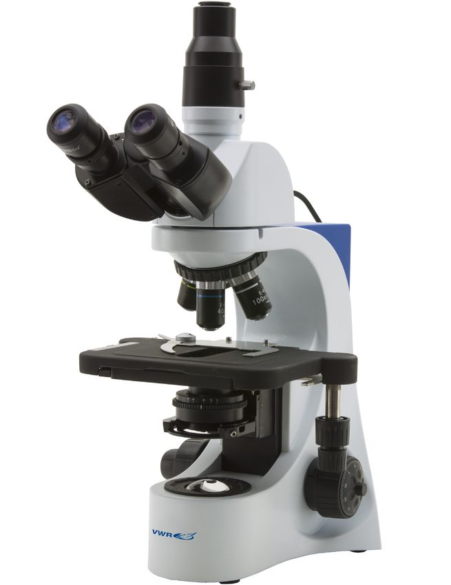
Warning
This microscope is a scientific precision instrument designed to last for many years with a minimum of main-
tenance. It is built to high optical and mechanical standards and to withstand daily use.
We remind you that this manual contains important information on safety and maintenance, and that it must
therefore be made accessible to the instrument users.
We decline any responsibility deriving from incorrect instrument use uses that does not comply with this
manual.

Safety Information

       Avoiding Electrical Shock

Before plugging in the power supply, make sure that the supplying voltage of your region matches with the
operation voltage of the equipment and that the lamp switch is in off position.

Users should observe all safety regulations of the region. The equipment has acquired the CE safety label.
However, users have full responsibility to use this equipment safely.
Please follow the guidelines below, and read this manual in its entirety to ensure safe operation of the unit.

Package Contents

DESCRIPTION                                                               QUANTITY

Microscope stand with nosepiece, stage, condenser                         1
Optical head (trinocular)                                                 1
Objective E-PLAN IOS 4x                                                   1
Objective E-PLAN IOS 10x                                                  1
Objective E-PLAN IOS 20x                                                  1
Objective E-PLAN IOS 40x                                                  1
Objective PLAN IOS MET 50x                                                1
Eyepiece WF10x/20mm                                                       2
Fluorescence attachment                                                   1
Dust cover                                                                1
Power supply output 6Vdc                                                  1

Unpacking
The microscope is housed in a moulded Styrofoam container. Remove the tape from the edge of the contain-
er and lift the top half of the container. Take care to ensure that the optical items (objectives and eyepieces)
do not fall out and get damaged. Using both hands (one around the neck and one around the base), lift the
microscope from the container and put it on a stable desk.

Place the observation head onto the top of the neck and tighten the lock-screw. Insert the eyepieces into the
eye tubes.

Connect the provided power supply to the power supply input jack on the rear of the microscope.

                                                            3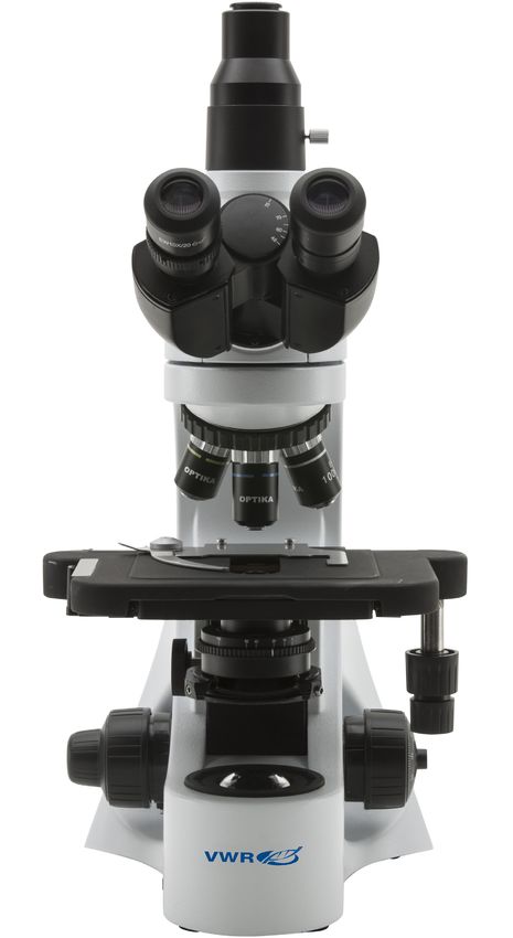
Intended use
For research and teaching use only. Not intended for any animal or human therapeutic or diagnostic use.

Symbols and conventions
The following chart is an illustrated glossary of the symbols that are used in this manual.

                                CAUTION
                                This symbol indicates a potential risk and alerts you to proceed with
                                caution

Product specifications
Head:                   Trinocular, 30° inclined, 360° rotating. Interpupillary adjustment 48-75 mm.
Eyepieces:               WF10X/20mm.
Nosepiece:              5-position reversed revolving nosepiece. Ball bearing rotation.
Objectives:             IOS E-PLAN 4x/0.10, 10x/0.25, 20x/0.40, 40x/0.65, and PLAN 50x/0.75 (no cover
slide).
Focusing system:        Coaxial coarse and fine.
Stage:                  Double layer mechanical sliding stage, dimensions 216x150mm, moving range
78x54mm.
                        Belt-drive in X direction.
Condenser:              Abbe condenser, sliding-in, N.A. 1.25 with centering system.
Illumination:           Transmitted light: P-LED3, with manual brightness control.
                        Epi-fluorescence: high-power white LED (for B ang G filtersets).
Power supply:           External power supply: Input 100-240Vac 50-60Hz / Output 6Vdc 1A.

                                                  4
Overview
                                PHOTO/VIDEO PORT

             DIOPTRIC
             ADJUSTMENT RING

  EYEPIECE

                                                   HEAD LOCKING
                                                   SCREW

 REVOLVING NOSEPIECE

     OBJECTIVE

                                                         STAGE

  IRIS DIAPHRAGM

                                                             TRANSLATION KNOBS
     CONDENSER

                                                       CONDENSER CENTERING
     BRIGHTNESS                                        SCREWS
     ADJUSTMENT
     (LEFT SIDE)

                               LED ILLUMINATOR

                                    5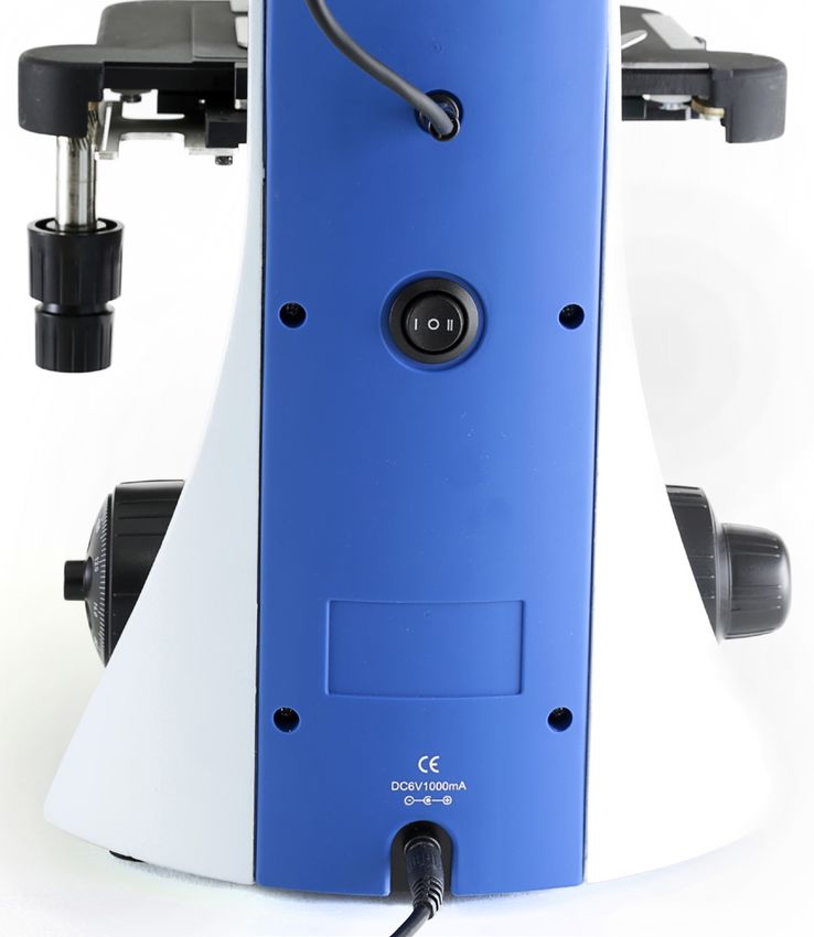
INTERPUPILLARY DISTANCE

        SLIDE CLAMP

  CONDENSER HEIGHT
  ADJUSTMENT

FINE FOCUSING KNOB

     COARSE FOCUSING KNOB
                                             TENSION
                                             ADJUSTMENT KNOB

                FOCUS STOP KNOB

                                  6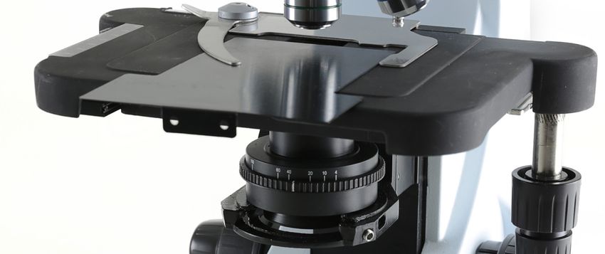
Using the microscope
Adjust the observation head
Loosen the lock-screw, turn the observation head to a comfortable position for observation, and then lock the
lock-screw.

Place the specimen on the stage
Lock the specimen slide on the mechanical stage using the slide clamp. Ensure that the specimen is centred
over the stage opening by adjusting the coaxial knobs of the stage

LED lamp settings – Transmitted illumination
The microscope is fitted with high brightness white LED illuminator. Press the selector switch on the back of
the
main body to I position. Turn the brightness adjustment knob to a brightness suitable for observation.

LED lamp settings – Epillumination
The microscope is fitted with high brightness LED illuminator. Press the selector switch on the back of the
main body to II position. Turn the brightness adjustment knob to a brightness suitable for observation.

Adjust interpupillary distance
Hold the right and left parts of the observation head by both hands and adjust the interpupillary distance by
turning the two parts until one circle of light can be seen.

Focus and diopter adjustment
Turn the dioptric adjustment ring on the left eyepiece to the zero position. Turn the coarse focus knob in order
to focus the slide with an objective with low magnification. Adjust the fine focus knob until you obtain a clear
and defined picture observing with the right eye, and then act on the left dioptric compensation ring observing
with the left eye. When the image appears in focus, choose the necessary objective with the revolving nose-
piece. Turn the tension-adjust-knob to get a suitable tension for the focus system.

Condenser adjustment
Turn the condenser adjustment knob to move the condenser up or down for a clear and uniform sample il-
lumination. The two condenser centring screws can be used to centre the condenser.

Set the numerical aperture
Adjust the aperture of the iris diaphragm to set the numerical aperture of the illuminator, thus controlling im-
age contrast and resolution.

                                                            7
HEAD LOCK SCREW

                                     LED ILLUMINATOR

                                      ILLUMINATOR LOCK
                                      SCREW
FILTER SELECTOR (1)

                      8
Using the fluorescence
Assembling the epi-fluorescence attachment
Take the attachment out of its packaging and put it onto the microscope stand, then tighten the attachment lock-
ing screw.
Place the optical head onto the top of the attachment and tighten the optical head locking screw. Connect the
cable from the epi-fluorescence attachment to the output jack on the rear of the microscope.
Lighting up the fluorescence LED light
Connect the external 6Vdc power supply to a wall socket, and plug its output to the jack on the rear of the mi-
croscope:
JACK FROM THE
ILLUMINATOR
(UPPER POSITION)
MAIN SWITCH
JACK FROM THE
POWER SUPPLY
(LOWER POSITION)
In order to light up the epi-fluorescence LED, press the main switch on the rear in position II. Then rotate the
brightness adjustment knob on the left to the desired value. Pull the filter selector (1) to right or left in order to
insert the fluorescence filter into the optical path. Put the filter selector (1) in the center if you want to use the
brightfield transmitted illumination. Unlike a mercury lamp system illumination doesn’t need any power-up time
for heating, and can be used immediately after switching on. Also, the LED source is pre-aligned in factory and
doesn’t need any alignment operation.
Looking at the fluorescent specimen
Focus on your sample, and adjust the light intensity as needed through the brightness adjustment knob. In order
to improve the darkness of the background (thus improving contrast), it is strongly suggested to put the provided
black plate under the stage):
SLIDE THE BLACK
PLATE BETWEEN
STAGE AND CLAMP
9Troubleshooting
Review the information in the table below to troubleshoot operating problems.
PROBLEM CAUSE SOLUTION
LIGHT DOESN’T TURN ON Power supply not connected Check that the 6Vdc power supply
jack is well inserted on the rear of the
microscope
Rotate the brightness adjustment con-
trol and check if there is an increase in
the light output
IMAGE CANNOT BE SEEN OR The iris diaphragm aperture Completely open the iris diaphragm
IS DARK. is not completely opened aperture
Brightness level is low Rotate the brightness adjustment po-
tentiometer
Objective is not aligned with Rotate the nosepiece until an objective
the optical axis is well inserted in the optical path (it
“clicks”)
IMAGE IS UNCLEAR, BLURRED Objectives or filters are dirty Wipe them clean
OR HAS INSUFFICIENT CON- The iris diaphragm aperture Open the iris diaphragm aperture
TRAST. is not opened correctly completely
Condenser at wrong height Rotate the condenser knob until you
see a uniform illumination
Repair and maintenance
Microscopy environment
This microscope is recommended for use in a clean, dry and shock free environment with a temperature of
0-40°C and a maximum relative humidity of 85 % (non condensing). Use a dehumidifier if needed.
After using the microscope
The microscope should always be kept vertical when moving it so that no moving parts, such as the eye-
pieces, fall out.
Never mishandle or impose unnecessary force on the microscope. Never attempt to service the microscope
yourself. Turn down the illumination intensity control and turn the light off. Cover the microscope with the in-
cluded dust cover, and keep it in a dry and clean place.
Electrical safety precautions
Before plugging in the power supply, make sure that the supplying voltage of your region matches with the
operation voltage of the equipment and that the lamp switch is in off-position.
Users should observe all safety regulations of the region. The equipment has acquired the CE safety label.
However, users do have full responsibility to use this equipment safely.
Cleaning the optics
If the optical parts require cleaning first use compressed air.
If that is not sufficient use a soft lint-free cloth with water and a mild detergent.
And as a final option use the piece of cloth moistened with a 3:7 mixture of ethanol and ether.
Note: ethanol and ether are highly flammable liquids. Do not use them near a heat source, near sparks or
near electric equipment. Use these chemicals in a well ventilated room. Remember to never wipe the surface
of any optical items with your hands. Fingerprints can damage the optics. Do not disassemble objectives or
eyepieces in an attempt to clean them.
For the best results, use the VWR cleaning kit (see catalogue number below).
If you need to send the microscope to manufacturer for maintenance, please use the packaging if possible.
10User replaceable accessories and spare parts
DESCRIPTION QUANTITY CAT. NO.
Eyepiece WF10x/20mm. 2 630-2000
Eyepiece WF15x. 2 630-2001
Eyepiece WF20x. 2 630-2002
Micrometer eyepiece WF10x/20mm. 1 630-2003
26x76 mm micrometric slide. Range 1 mm, div. 0,01 mm. 1 630-1650
Objective 4x/0,10 E-PLAN IOS. 1 630-1639
Objective 10x/0,25 E-PLAN IOS. 1 630-1640
Objective 20x/0,40 E-PLAN IOS. 1 630-1641
Objective 40x/0,65 E-PLAN IOS 1 630-1642
Objective 60x/0,80 E-PLAN IOS. 1 630-2049
Objective 100x/1,25 E-PLAN IOS (Oil). 1 630-1643
Objective PLAN IOS MET 50x/0.75. 1 630-2159
Photo adapter for APS-C and Full Frame Reflex cameras. 1 630-1645
C-Mount adapter for 1/2” sensor. 1 630-1644
Solar battery pack. 1 630-1637
Complete Phase Contrast Set with IOS PLAN obj. 10x, 20x, 40x, 1 630-2059
100x , with Darkfifi eld position.
Polarising set, filters only. 1 630-2285
Rotating table for polarising set. 1 630-2011
Darkfifield condenser for Dry Objectives. 1 630-2060
C-Mount adapter for 2/3” sensor. 1 630-2530
11Technical service
Web Resources
Visit the VWR’s website at www.vwr.com for:
• Complete technical service contact information
• Access to VWR’s Online Catalogue, and information about accessories and related products
• Additional product information and special offers
Contact us For information or technical assistance contact your local VWR representative or visit. www.
vwr.com.
Warranty
VWR International warrants that this product will be free from defects in material and workmanship for a
period of five (5) years from date of delivery. If a defect is present, VWR will, at its option and cost, repair,
replace, or refund the purchase price of this product to the customer, provided it is returned during the war-
ranty period. This warranty does not apply if the product has been damaged by accident, abuse, misuse, or
misapplication, or from ordinary wear and tear. If the required maintenance and inspection services are not
performed according to the manuals and any local regulations, such warranty turns invalid, except to the ex-
tent, the defect of the product is not due to such non-performance.
Items being returned must be insured by the customer against possible damage or loss. This warranty shall
be limited to the aforementioned remedies. IT IS EXPRESSLY AGREED THAT THIS WARRANTY WILL BE
IN LIEU OF ALL WARRANTIES OF FITNESS AND IN LIEU OF THE WARRANTY OF MERCHANTABILITY.
Compliance with local laws and regulations
The customer is responsible for applying for and obtaining the necessary regulatory approvals or other au-
thorizations necessary to run or use the Product in its local environment. VWR will not be held liable for any
related omission or for not obtaining the required approval or authorization, unless any refusal is due to a
defect of the product.
12Disposal
This equipment is marked with the crossed out wheeled bin symbol to indicate that this equipment must not
be disposed of with unsorted waste.
Instead it is your responsibility to correctly dispose of your equipment the end of its life cycle by handling it
over to an authorized facility for separate collection and recycling. It is also your responsibility to decontami-
nate the equipment in case of biological, chemical and/or radiological contamination, so as to protect from
health hazards the persons involved in the disposal and recycling of the equipment.
For more information about where you can drop off your waste equipment, please contact your local dealer
from whom you originally purchased this equipment.
By doing so, you will help to conserve natural and environmental resources and you will ensure that your
equipment is recycled in a manner that protects human health.
Thank you
13Australia Hungary Singapore
VWR International, Pty Ltd. VWR International Kft. VWR Singapore Pte Ltd
Unit 1/31 Archimedes Place Simon László u. 4. 18 Gul Drive
Murarrie, Queensland 4172 4034 Debrecen Singapore 629468
Tel.: 1300 727 696 Tel.: (52) 521-130 Tel.: +65 6505 0760
Fax: 1300 135 123 Fax: (52) 470-069 Fax: +65 6264 3780
E-mail: info@hu.vwr.com E-mail: sales@sg.vwr.com
Austria
VWR International GmbH India
Graumanngasse 7 VWR Lab Products Private Limited Spain
1150 Vienna 135/12, Brigade Towers, 2nd Floor VWR International Eurolab S.L.
Tel.: +43 1 97 002 0 Front wing, Brigade Road, C/ Tecnología 5-17
Fax: +43 1 97 002 600 Bengaluru, India – 560 025 A-7 Llinars Park
E-mail: info@at.vwr.com Tel.: +91-80-41117125/26 (Bengaluru) 08450 - Llinars del Vallès
Tel.: +91-2522-647911/922 (Mumbai) Barcelona
Belgium Fax: +91-80-41117120 Tel.: 902 222 897
VWR International bvba E-mail: vwr_india@vwr.com Fax: 902 430 657
Researchpark Haasrode 2020 E-mail: info@es.vwr.com
Geldenaaksebaan 464 Ireland / Northern Ireland
3001 Leuven VWR International Ltd / Sweden
Tel.: 016 385 011 VWR International (Northern Ireland) Ltd VWR International AB
Fax: 016 385 385 Orion Business Campus Fagerstagatan 18a
E-mail: customerservice@be.vwr.com Northwest Business Park 163 94 Stockholm
Ballycoolin Tel.: 08 621 34 00
China Dublin 15 Fax: 08 621 34 66
VWR International China Co., Ltd Tel.: 01 88 22 222 E-mail: kundservice@se.vwr.com
Rm.219, 2100 Dongming Road Fax: 01 88 22 333
Pudong New District E-mail: sales@ie.vwr.com Switzerland
Shanghai 200123 VWR International GmbH
Tel.: +86-21-5898 6888 Italy Lerzenstrasse 16/18
Fax: +86-21-5855 8801 VWR International PBI S.r.l. 8953 Dietikon
E-mail: info_china@vwr.com Via San Giusto 85 Tel.: 044 745 13 13
20153 Milano (MI) Fax: 044 745 13 10
Czech Republic Tel.: 02-3320311/02-487791 E-mail: info@ch.vwr.com
VWR International s. r. o. Fax: 800 152999/02-40090010
Veetee Business Park E-mail: info@it.vwr.com Turkey
Pražská 442 Pro Lab Laboratuar Teknolojileri Ltd.Şti.
CZ - 281 67 Stříbrná Skalice The Netherlands a VWR International Company
Tel.: +420 321 570 321 VWR International B.V. Orta Mah. Cemal Gürsel Caddesi
Fax: +420 321 570 320 Postbus 8198 Ördekcioglu Işmerkezi No.32/1
E-mail: info@cz.vwr.com 1005 AD Amsterdam 34896 Pendik - Istanbul
Tel.: 020 4808 400 Tel.: +90216 598 2900
Denmark Fax: 020 4808 480 Fax: +90216 598 2907
VWR - Bie & Berntsen E-mail: info@nl.vwr.com Email: info@pro-lab.com.tr
Transformervej 8
2730 Herlev New Zealand UK
Tel.: 43 86 87 88 Global Science - A VWR Company VWR International Ltd
Fax: 43 86 87 90 241 Bush Road Customer Service Centre
E-mail: info@dk.vwr.com Albany 0632, Auckland Hunter Boulevard - Magna Park
Tel.: 0800 734 100 Lutterworth
Finland Fax: 0800 999 002 Leicestershire
VWR International Oy E-mail: sales@globalscience.co.nz LE17 4XN
Valimotie 9 Tel.: 0800 22 33 44
00380 Helsinki Norway Fax: 01455 55 85 86
Tel.: 09 80 45 51 VWR International AS E-mail: uksales@uk.vwr.com
Fax: 09 80 45 52 00 Haavard Martinsens vei 30
E-mail: info@fi.vwr.com 0978 Oslo
Tel.: 02290
France Fax: 815 00 940
VWR International S.A.S. E-mail: info@no.vwr.com
Le Périgares – Bâtiment B GO TO VWR.COM FOR THE
201, rue Carnot Poland LATEST NEWS, SPECIAL OFFERS
94126 Fontenay-sous-Bois cedex VWR International Sp. z o.o.
Tel.: 0 825 02 30 30 (0,15 € TTC/min) Limbowa 5 AND DETAILS OF YOUR LOCAL
Fax: 0 825 02 30 35 (0,15 € TTC/min) 80-175 Gdansk VWR DISTRIBUTOR
E-mail: info@fr.vwr.com Tel.: 058 32 38 200 do 204
Fax. 058 32 38 205
Germany E-mail: info@pl.vwr.com
VWR International GmbH
Hilpertstraße 20a Portugal
D - 64295 Darmstadt VWR International -
Freecall: 0800 702 00 07 Material de Laboratório, Lda
Fax: 0180 570 22 22* Edifício Neopark
Email: info@de.vwr.com Av. Tomás Ribeiro, 43- 3 D
*0,14 €/Min. aus d. dt. Festnetz 2790-221 Carnaxide
Tel.: 21 3600 770
Fax: 21 3600 798/9
E-mail: info@pt.vwr.com
14VWR
Microscope series 384
MANUEL D’UTILISATION
Modèle European Catalogue Number
TL384 FL 630-1938
Version: 2
du: 19, 03, 2015Adresse du Fabricant
Europe
VWR International bvba
Researchpark Haasrode 2020
Geldenaaksebaan 464
B-3001 Leuven
+ 32 16 385011
http://be.vwr.com
Pays d’origine: ITALIA
Contenu
Avertissement
Précautions
Contenu de l’emballage
Déballage
Usage
Symboles et conventions
Caractéristiques techniques
Description
Utilisation du microscope
Utilisation de la fluorescence
Résolution de problèmes
Réparation et entretien
Accessoires et pièces de rechanges
Service technique
Garantie
Conformité à la législation et aux réglementations locales
Ramassage
16Avertissement
Le présent microscope est un appareil scientifique de précision créé pour offrir une durrée de vie de plusieurs
années avec un niveau d’entretien mininum. Les meilleurs composants optiques et mécaniques ont été utili-
sés pour sa conception ce qui fond de lui un appareil idéal pour une utilisation journalière.
Ce guide contient des informations importantes sur la sécurité et l’entretien du produit et par conséquent il
doit être accessible à tous ceux qui utilisent cet insrument.
Nous déclinons toute responsabilité quant à des utilisations de l’instrument non conformes au présent ma-
nuel.
Précautions
Précautions de sécurité sur le système électrique
Avant de connecter le câble d’alimentation au réseau électrique assurez vous que la tension d’entrée soit
compatible avec celle de l’appareil et que l’interrupteur de l’éclairage soit en position arrêt.
L’utilisateur devra consulter les normes de sécurités de son pays. L’appareil inclu une étiquette de sécurité
C.E. Dans tous les cas, l’utilisateur assume toute responsabilité relative à l’utilisation sûre de l’appareil.
Suivre les directives ci-dessous et lire ce manuel dans son intégralité pour un fonctionnement sûr de l’instru-
ment.
Contenu de l’emballage
DESCRIPTION QUANTITÉ
Statif avec revolver, platine et condenseur 1
Tête optique (trinoculaire) 1
Objectif E-PLAN IOS 4x 1
Objectif E-PLAN IOS 10x 1
Objectif E-PLAN IOS 20x 1
Objectif E-PLAN IOS 40x 1
Objectif IOS PLAN MET 50x. 1
Oculaire WF10x/20mm 2
Éclairage pour fluorescence 1
Housse de protection 1
Sortie de l’alimentation 6Vdc 1
Déballage
Le microscope est livré dans un emballage en polystyrène. Après avoir enlevé le papier adhésif de l’embal-
lage, enlevez la partie supérieure de l’emballage. Faites attention à ce que les composants optiques (objec-
tifs et oculaires) ne tombent pas ou ne s’endommagent pas. Sortez le microscope de son emballage et posez
le sur une surface stable et plate.
Fixez la tête d’observation sur la partie supérieure du corps du microscope en utilisant les vis de fixation cor-
respondantes. Introduisez l’oculaire dans le porte oculaire.
Connectez l’alimentation à la prise jack située sur partie postérieure du microscope.
17Usage
Uniquement pour la recherche. Non destiné à usage thérapeutique ou diagnostique sur animaux ou êtres
humains.
Symboles et conventions
Le tableau suivant est un glossaire illustré des symboles qui sont utilisés dans ce manuel.
ATTENTION
Ce symbole indique un risque potentiel et vous avertit de procéder
avec prudence
Caractéristiques techniques
Tête: Trinoculaire, inclinée à 30º, rotative sur 360°. Distance interpupillaire réglable 48-75
mm.
Oculaires: WF10X/20mm.
Révolver: 5-positions. Rotation sur roulements à billes.
Objectifs: IOS E-PLAN: 4x/0.10, 10x/0.25, 20x/0.40, 40x/0.65 et 50x/0.75 (sans lame couvre ob-
ject).
Système de mise
au point: Avec commandes de mise au point macrométrique et micrométrique coaxiales.
Platine: Double niveau avec sur-platine mécanique, 216x150 mm;
rang de mouvement de 78x54 mm. Entraînement par courroie en direction X.
Condenseur: Condenseur d’Abbe O.N. 1, 25; centrable.
Éclairage: Éclairage transmis: P-LED3, avec variateur d’intensité.
Épi-fluorescence: LED blanche à haute puissance.(pour les filtres Bleu et Vert).
Alimentation: Alimentation externe: entrée 100-240Vac 50-60Hz / sortie 6Vdc 1A .
18Description
SORTIE PHOTO VIDÉO
RÉGLAGE DE LA DISTANCE
INTER PUPILLAIRE
OCULAIRES
VIS DE FIXATION DE
LA TÊTE
RÉVOLVER
OBJECTIFS
SURPLATINE
MÉCANIQUE
DIAPHRAGME À IRIS
COMMANDES
CONDENSEUR COAXIALES
AJUSTEMENT
LUMINOSITE VIS DE RÉGLAGE DE
(CÔTÉ GAUCHE) CONDENSEUR
ECLAIRAGE LED
19RÉGLAGE DE LA DISTANCE
INTER PUPILLAIRE
PINCE POUR MAINTENIR LES
PRÉPARATIONS
RÉGLAGE DE LA
HAUTEUR DU
CONDENSEUR
COMMANDE DE MISE AU
POINT MICROMÉTRIQUE
COMMANDE DE MISE
AU POINT
COMMANDE DE
MACROMÉTRIQUE
RÉGLAGE DE TENSION
VERROUILLAGE DU
FOYER
20Utilisation du microscope
Réglage de la tête d’observation
Dévissez légèrement les vis de fixation de façon à faire pivoter la tête jusqu’à obtenir une position confortable
pour l’observation avant de revisser à nouveau.
Positionnement de la préparation sur la platine mécanique
Fixez la préparation à la platine mécanique à l’aide de la pince. Réglez les commandes coaxiales qui se
situent sur le côté ddu statif, et assurez vous que la préparation se situe au centre du champ de vision.
Réglage de l’éclairage – Éclairage transmis
Le microscope inclut un éclairage LED à haute luminosité. Appuyer sur l’interrupteur à l’arrière du corps
principal en position I. Tourner la commande de réglage de la luminosité pour une luminosité approprié à
l’observation.
Les réglages de la lampe LED – Epi éclairage
Le microscope est équipé d’éclairage LED blanche à haute luminosité. Appuyer sur l’interrupteur à l’arrière du
corps principal en position II. Tourner la commande de réglage de la luminosité pour une luminosité approprié
à l’observation.
Réglage de la distance inter pupillaire
Réglez la distance interpupillaire des tubes portes oculaires jusqu’à obtenir la vision d’un unique champ lumi-
neux circulaire. Une fois le réglage terminé, tournez les deux anneaux de compensation dioptrique jusqu’à
arriver au zéro sur l’échelle graduée des oculaires.
Réglage de la mise au point et de la compensation dioptrique
Tournez la bague du réglage dioptrique sur l’oculaire gauche sur la position zéro. Tournez la commande de
mise au point macrométrique afin de focaliser la lame avec un objectif à faible grossissement. Réglez la
commande de mise au point micrométrique jusqu’à l’obtention d’une image claire et définie en observant
avec l’œil droit, puis agir sur la bague de la compensation dioptrique gauche en observant avec l’œil gauche.
Lorsque l’image apparaît claire et définie passez à l’objectif suivant en tournant le revolver. Tournez la com-
mande de réglage de la tension pour obtenir une tension appropriée du système de mise au point.
Réglage du condenseur
Montez ou descendez le condenseur en utilisant la commande correspondante afin d’obtenir un éclairage
clair et uniforme de l’objet. Pour centrer le condenseur utilisez les deux vis de centrage.
Réglage de l’ouverture numérique
Ajustez l’ouverture du diaphragme à iris pour régler l’ouverture numérique de l’éclairage, ceci cous permet-
tera d’obtenir le contraste et la résolution de l’image.
21VIS DE BLOCAGE DE LA TÊTE
ÉCLAIRAGE LED
VIS DE BLOCAGE DE
L’ÉCLAIRAGE
SÉLECTEUR DE FILTRE
22Utilisation de la fluorescence
Montage de la lampe à épi-fluorescence
Extraire l’éclairage de son emballage et placez le sur le statif du microscope, puis serrez la vis de blocage de
l’éclairage. Placez la tête optique au dessus de l’éclairage et serrer la vis de blocage de la tête optique. Bran-
chez le câble de l’éclairage à épi-fluorescence à la prise de sortie à l’arrière du microscope.
Allumer l’éclairage à fluorescence LED
Connectez l’alimentation externe 6V à une prise murale et branchez sa sortie à la prise à l’arrière du microscope:
JACK DE L’ÉCLAIRAGE
INTERRUPTEUR
PRINCIPAL
JACK DE
L’ALIMENTATEUR
Pour allumer l’épi-fluorescence LED, appuyez sur placez l’interrupteur principal à l’arrière sur II. Puis tourner la
commande de réglage de la luminosité vers la gauche sur la valeur désirée. Tirer le sélecteur de filtre (1) à droite
ou à gauche afin d’insérer le filtre de fluorescence desiré dans le chemin optique.
Placez le sélecteur de filtre (1) au le centre si vous souhaitez utiliser la lumière transmise pour fond clair.
Contrairement à un système déclairage par lampe à mercure, l’éclairage LED n’a pas besoin d’une periode de
préchauffement avant son utilisation et peut être utilisé immédiatement après la mise en marche. En outre, la
source LED est pré-centrée en usine et ne nécessite aucune opération d’alignement.
Observation des échantillons fluorescents
Concentrez-vous sur votre échantillon, et réglez l’intensité lumineuse en fonction des besoins grâce à la com-
mande de réglage de la luminosité. Afin d’améliorer l’obscurité de l’arrière-plan (améliorant ainsi le contraste), il
est fortement recommandé de mettre la plaque noire fournie sous la platine):
PLAQUE NOIRE À
INSERER SOUS LA
PLATINE
23Résolution de problèmes
PROBLÈME CAUSE SOLUTION
L’ÉCLAIRAGE NE L’alimentation n’est pas Vérifiez l’alimentation 6Vdc soit bien
S’ALLUME PAS branché inséré à l’arrière du microscope.
Potentiomètre Tourner le potentiomètre de réglage de
la luminosité et vérifier si une augmen-
tation de lumière se produit.
L’IMAGE NE SE VOIT PAS OU Le diaphragme n’est pas Ouvrez complètement le diaphragme
EST SOMBRE. complètement ouvert.
Le niveau de luminosité est Tourner le potentiomètre de réglage de
faible. la luminosité.
L’objectif n’est pas aligné Tournez le revolver jusqu’à ce que
avec l’axe optique. l’objectif soit bien aligné dans le trajet
optique, vous entendrez un « clic »
L’IMAGE EST FLOUE OU LE Les objectifs ou les filtres Les nettoyer.
CONTRASTE EST sont sales.
INSUFFISANT Le diaphragme n’est pas Ouvrez complètement le diaphragme.
complètement ouvert.
Le condenseur n’est pas à la Tournez la commande du condensa-
bonne hauteur teur jusqu’à vous voyez un éclairage
uniforme
Réparation et entretien
Environnement de travail
Il est conseillé d’utiliser le microscope dans un environnement propre et sec, protégé des impactes, à une
température comprise entre 0°C y 40°C et avec une humidité relative maximale de 85% (en absence de
condensation). Il est conseillé d’utiliser un déshumidificateur si nécessaire.
Conseils avant et après l’utilisation du microscope
- Maintenir le microscope toujours en position verticale lorsque vous le déplacez. Assurez vous que les
pièces mobiles (oculaires) ne tombent pas.
- Manipulez avec attention le microscope en évitant de le forcer.
- Ne réparez pas le microscope vous même
- Éteindre immédiatement la lumière après avoir utilisé le microscope, couvrez le avec la housse prévue à cet
effet et conservez le dans un endroit propre et sec.
Précaution de sécurité sur le système électrique
Avant de connecter le câble d’alimentation sur le réseau électrique assurez vous que la tension d’entrée soit
compatible avec celle de l’appareil et que l’interrupteur de l’éclairage soit en position arrêt.
L’utilisateur devra consulter les normes de sécurités de son pays. L’appareil inclu une étiquette de sécurité
C.E. Dans tous les cas, l’utilisateur assume toute responsabilité relative à l’utilisation sûre de l’appareil.
Nettoyage des optiques
Si vous souhaitez nettoyer les optiques, utilisez dans un premier temps de l’air comprimé Si cela n’est pas
suffisant, utilisez alors un chiffon non effiloché, humidifié avec un peu d’eau et avec un détergent délicat.
Comme dernière option, il est possible d’utiliser un chiffon humide avec une solution de 3:7 d’éthanol et
d’éther. Attention: l’éthanol et l’éther sont des substances hautement inflammables.
Ne les utilisez pas près d’une source de chaleur, d’étincelles ou d’appareils électriques.
Les substances chimiques doivent être utilisées dans un environnement aéré Ne pas frotter la superficie
d’aucun des composants optiques avec les mains. Les empreintes digitales peuvent endommager les parties
24optiques.
Pour les meilleurs résultats, utiliser le kit de nettoyage (code ci-dessous).
Conserver l’emballage d’origine dans le cas où il serait nécessaire de retourner le microscope au
fournisseur pour un entretien ou une réparation.
Accessoires et pièces de rechanges
DESCRIPTION QUANTITÉ CAT. NO.
Oculaire WF10x/20mm 2 630-2000
Oculaire WF15x 2 630-2001
Oculaire WF20x 2 630-2002
Oculaire micrométrique WF10x/20mm 1 630-2003
Lame micrométrique 26x76 mm. Rang 1 mm, div. 0,01 mm 1 630-1650
Objectif IOS E-PLAN 4x/0,10. 1 630-1639
Objectif IOS E-PLAN 10x/0,25. 1 630-1640
Objectif IOS E-PLAN 20x/0,40. 1 630-1641
Objectif IOS E-PLAN 40x/0,65. 1 630-1642
Objectif IOS E-PLAN 60x/0,80. 1 630-2049
Objectif IOS E-PLAN 100x/1,25 (Huile). 1 630-1643
Objectif IOS PLAN MET 50x/0.75. 1 630-2159
Adaptateur pour APS-C et Full Frame Réflex caméras 1 630-1645
Adaptateur monture C pour capteur 1/2” 1 630-1644
Batterie solaire. 1 630-1637
Jeu complet d’objectifs pour contraste de phase IOS PLAN 10x, 20x, 1 630-2059
40x, 100x, avec position pour fond noir
Kit de polarisation, seulement les filtres 1 630-2285
Platine rotative pour kit de polarisation 1 630-2011
Condenseur fond noir pour objectifs secs 1 630-2060
Adaptateur monture C pour capteur 2/3” 1 630-2530
25Service technique
Ressources Web
Visitez le site Web de VWR à l’adresse www.vwr.com pour:
• Coordonnées complètes du service technique.
• Accès au catalogue en ligne de VWR et à des informations sur les accessoires et produits connexes.
• Informations supplémentaires sur les produits et les offres spéciales.
Contactez-nous Pour plus d’informations ou une assistance technique, contactez votre représentant VWR
local ou visitez le site www.vwr.com.
Garantie
VWR International garantit ce produit pièces et main-d’œuvre pour une durée de cinq (5) ans à compter
de la date de livraison. En cas de vice, VWR pourra, à sa discrétion et à ses frais, réparer, remplacer ou
rembourser au client le prix d’achat du produit, à condition qu’il lui soit retourné au cours de la période de
garantie. Cette garantie n’est pas applicable si le dommage provient d’un accident, d’une utilisation abusive
ou incorrecte, d’une mauvaise application ou de l’usure normale du produit. Cette garantie deviendrait non
valide dans le cas où les services de maintenance et de vérification requis ne seraient pas exécutés confor-
mément aux manuels et réglementations locales, sauf exception si le défaut du produit n’est pas imputable
à cette non exécution.
Il est recommandé au client d’assurer les éléments retournés contre les risques éventuels d’endommagement
ou de perte. Cette garantie se limite aux réparations susmentionnées. IL EST EXPRESSÉMENT CONVENU
QUE LA PRÉSENTE GARANTIE SE SUBSTITUE À TOUTES LES GARANTIES DE CONFORMITÉ ET DE
VALEUR MARCHANDE.
Conformité à la législation et aux réglementations locales
Le client est chargé de la demande et de l’obtention des approbations réglementaires et autres autorisations
nécessaires à l’utilisation ou à l’exploitation du Produit dans l’environnement local. VWR ne saura être tenu
responsable de toute omission ou non obtention des approbations ou autorisations requises, sauf exception
si le refus est dû à un défaut du produit.
26Ramassage
Le symbole du conteneur qui figure sur l’appareil électrique ou sur son emballage indique que le produit de-
vra être, à la fin de sa vie utile, séparé du reste des résidus. Pour la gestion du ramassage sélectif du présent
instrument, l’utilisateur qui souhaite éliminer l’appareil devra se mettre en contact avec le fabricant et suivre
la procédure que celui-ci a adopté pour permettre le ramassage sélectif de l’appareil. Le ramassage sélectif
correct de l’appareil pour son recyclage, traitement et élimination compatible avec l’environnement contribue
à éviter d’éventuels effets négatifs sur l’environnement et la santé et favorise la réutilisation et/ou recyclage
des composants de l’appareil. L’élimination du produit de manière abusive de la part de l’utilisateur entraînera
l’application de sanctions administratives sur la norme en vigueur.
Merci.
27Allemagne Hongrie République Tchèque
VWR International GmbH VWR International Kft. VWR International s. r. o.
Hilpertstraße 20a Simon László u. 4. Veetee Business Park
D - 64295 Darmstadt 4034 Debrecen Pražská 442
Freecall: 0800 702 00 07 Tel.: (52) 521-130 CZ - 281 67 Stříbrná Skalice
Fax: 0180 570 22 22* Fax: (52) 470-069 Tel.: +420 321 570 321
Email: info@de.vwr.com E-mail: info@hu.vwr.com Fax: +420 321 570 320
*0,14 €/Min. aus d. dt. Festnetz E-mail: info@cz.vwr.com
Inde
Australie VWR Lab Products Private Limited Royaume-Uni
VWR International, Pty Ltd. 135/12, Brigade Towers, 2nd Floor VWR International Ltd
1/31 Archimedes Place Front wing, Brigade Road, Customer Service Centre
Murarrie, Queensland, 4172 Bengaluru, India – 560 025 Hunter Boulevard - Magna Park
Tel.: 1300 727 696 Tel.: +91-80-41117125/26 (Bengaluru) Lutterworth
Fax: 1300 135 123 Tel.: +91-2522-647911/922 (Mumbai) Leicestershire
Fax: +91-80-41117120 LE17 4XN
Autriche Tel.: 0800 22 33 44
VWR International GmbH Irlande / Irlande du Nord Fax: 01455 55 85 86
Graumanngasse 7 VWR International Ltd / E-mail: uksales@uk.vwr.com
1150 Wien VWR International (Northern Ireland) Ltd
Tel.: 01 97 002 0 Orion Business Campus Singapour
Fax: 01 97 002 600 Northwest Business Park VWR Singapore Pte Ltd
E-mail: info@at.vwr.com
Ballycoolin 18 Gul Drive
Belgique Dublin 15 Singapore 629468
VWR International bvba Tel.: 01 88 22 222 Tel.: +65 6505 0760
Researchpark Haasrode 2020 Fax: 01 88 22 333 Fax: +65 6264 3780
Geldenaaksebaan 464 E-mail: sales@ie.vwr.com E-mail: sales@sg.vwr.com
3001 Leuven
Tel.: 016 385 011 Italie Suède
Fax: 016 385 385 VWR International PBI S.r.l. VWR International AB
E-mail: customerservice@be.vwr.com Via San Giusto 85 Fagerstagatan 18a
20153 Milano (MI) 163 94 Stockholm
Chine Tel.: 02-3320311/02-487791 Tel.: 08 621 34 00
VWR International China Co., Ltd Fax: 800 152999/02-40090010 Fax: 08 621 34 66
Rm.219, 2100 Dongming Road E-mail: info@it.vwr.com E-mail: kundservice@se.vwr.com
Pudong New District
Shanghai 200123 Norvège Suisse
Tel.: +86-21-5898 6888 VWR International AS VWR International GmbH
Fax: +86-21-5855 8801 Haavard Martinsens vei 30 Lerzenstrasse 16/18
E-mail: info_china@vwr.com 0978 Oslo 8953 Dietikon
Tel.: 0 2290 Tel.: 044 745 13 13
Danemark Fax: 815 00 940 Fax: 044 745 13 10
VWR - Bie & Berntsen E-mail: info@no.vwr.com E-mail: info@ch.vwr.com
Transformervej 8
2730 Herlev Nouvelle-Zélande Turquie
Tel.: 43 86 87 88 Global Science - A VWR Company Pro Lab Laboratuar Teknolojileri Ltd.Şti.
Fax: 43 86 87 90 241 Bush Road a VWR International Company
E-mail: info@dk.vwr.com Albany 0632, Auckland Orta Mah. Cemal Gürsel Caddesi
Tel.: 0800 734 100 Ördekcioglu Işmerkezi No.32/1
Espagne Fax: 0800 999 002 34896 Pendik - Istanbul
VWR International Eurolab S.L. E-mail: sales@globalscience.co.nz Tel.: +90216 598 2900
C/ Tecnología 5-17 Fax: +90216 598 2907
A-7 Llinars Park Pays-Bas Email: info@pro-lab.com.tr
08450 - Llinars del Vallès VWR International B.V.
Barcelona Postbus 8198
Tel.: 902 222 897 1005 AD Amsterdam
Fax: 902 430 657 Tel.: 020 4808 400
E-mail: info@es.vwr.com Fax: 020 4808 480
E-mail: info@nl.vwr.com
Finlande
VWR International Oy Pologne
Valimotie 9 VWR International Sp. z o.o.
00380 Helsinki Limbowa 5 RENDEZ-VOUS SUR WWW.
Tel.: 09 80 45 51 80-175 Gdansk
Fax: 09 80 45 52 00 VWR.COM ET RETROUVEZ
Tel.: 058 32 38 200 do 204
E-mail: info@fi.vwr.com Fax. 058 32 38 205 NOS NOUVEAUTÉS ET OFFRES
E-mail: info@pl.vwr.com SPÉCIALES
France
VWR International S.A.S.
Le Périgares – Bâtiment B
Portugal
VWR International - Material de Labo-
201, rue Carnot
94126 Fontenay-sous-Bois cedex ratório, Lda
Tel.: 0 825 02 30 30 (0,15 € TTC/min) Edifício Neopark
Fax: 0 825 02 30 35 (0,15 € TTC/min) Av. Tomás Ribeiro, 43- 3 D
E-mail: info@fr.vwr.com 2790-221 Carnaxide
Tel.: 21 3600 770
Fax: 21 3600 798/9
E-mail: info@pt.vwr.com
28VWR
Mikroskop 384 Serie
BEDIENUNGSANLEITUNG
Model European Catalogue Number
TL384 FL 630-1938
Version: 2
Datum: 19, 03, 2015Herstellersadresse
Europe
VWR International bvba
Researchpark Haasrode 2020
Geldenaaksebaan 464
B-3001 Leuven
+ 32 16 385011
http://be.vwr.com
Ursprungsland: ITALY
Inhalt
Warnung
Sicherheitshinweise
Lieferumfang
Auspacken
Verwendungsempfehlungen
Zeichen
Technische daten
Überblick
Verwendung des Mikroskops
Verwendung der Fluoreszenz
Störungssuche
Wartung
Zubehörteilen
Technischer Kundendienst
Gewährleistung
Befolgung lokaler Gesetze und anderer Rechtsvorschriften
Wiederverwertung
30Warnung
Dieses Mikroskop ist ein wissenschaftliches Präzisionsgerät, es wurde entwickelt für eine jahrelange Verwen-
dung bei einer minimalen Wartung. Dieses Gerät wurde nach den höchsten optischen und mechanischen
Standards und zum täglichen Gebrauch hergestellt.
Diese Bedienungsanleitung enthält wichtige Informationen zur korrekten und sicheren Benutzung
des Geräts. Diese Anleitung soll allen Benutzern zur Verfügung stehen.
Wir lehnen jede Verantwortung für eine fehlerhafte, in dieser Bedienungsanleitung nicht gezeigten Verwen-
dung Ihrer Produkte ab.
Sicherheitshinweise
Elektrische Vorsichtsmaßnahmen
Bevor Sie das Netzkabel anstecken, vergewissern Sie sich, dass die Spannung für das Mikroskop geeignet
ist und dass der Beleuchtungsschalter sich in Position OFF befindet.
Beachten Sie alle Sicherheitsvorschriften des Arbeitsplatzes, an dem Sie mit dem Mikroskop arbeiten. Das
Gerät entspricht den CE-Normen. Die Benutzer tragen während der Nutzung des Geräts die volle Verantwor-
tung dafür.
Lieferumfang
BESCHREIBUNG MENGE
Stativ Mikroskop mit Revolver, Kreuztisch, Kondensor 1
Optischer Kopf (Trinokular) 1
Objektiv E-PLAN IOS 4x 1
Objektiv E-PLAN IOS 10x 1
Objektiv E-PLAN IOS 20x 1
Objektiv E-PLAN IOS 40x 1
Objektiv PLAN IOS MET 50x 1
Okular WF10x/20mm 2
Beleuchtung für Fluoreszenz 1
Staubabdeckung 1 1
Netzteil 6Vdc 1
Auspacken
Das Mikroskop befindet sich in einer Polystyrolverpackung. Nehmen Sie das Klebeband von der Verpackung
ab und heben Sie dann den oberen Teil der Verpackung. Bitte beachten Sie dabei, dass die optischen Kom-
ponenten (Objektive, Okulare) nicht beschädigt werden oder fallen. Halten Sie das Mikroskop mit beiden
Händen (eine rund um das Stativ und eine um den Fuß), ziehen Sie es aus der Verpackung raus und stellen
sie es auf eine flache, stabile Oberfläche.
Befestigen Sie den Kopf auf dem Stativ mit Hilfe der Spannschraube. Setzen Sie die Okulare in den Tuben
ein.
Verbinden Sie das Netzteil zur Steckdose auf der Rückseite des Mikroskops.
31Verwendungsempfehlungen
Nur für Forschung. Nicht für therapeutische Verwendung.
Zeichen
Die folgende Tabelle zeigt die Symbole, die in dieser Anleitung verwendet werden.
ACHTUNG
Dieses Symbol zeigt eine potentielle Gefahr und warnt, mit Vorsicht
zu verfahren.
Technische daten
Kopf: Trinokular, 30° schrägeinblick, 360° drehbar. Verstellbarer Augenabstand 48-75mm.
Okulare: WF10X/20mm.
Revolver: 5-fach invers. Drehung auf Kugellager.
Objektive: E-PLAN IOS 4x/0.10, 10x/0.25, 20x/0.40, 40x/0.65, und PLAN 50x/0.75 (ohne Präparateschutz).
Fokus: Koaxiale Grob- und Feintrib.
Kreuztisch: Doppelschicht, umsetzbar, Abmessung 216x150mm, Umsetzung range 78x54mm.
Belt- Drive in X Richtung.
Kondensor: Abbe Kondensor, slidin-in, N.A. 1.25 mit Zentrierungssystem.
Beleuchtung: Durchlicht: P-LED3, mit manueller Helligkeitskontrolle.
Helligkeitskontrolle: Epi-Fluoreszenz: hocheffiziente weisse LED (für blaue und grüne Filter).
Netzteil: Außennetzteil: Input 100-240Vac 50-60Hz / Output: 6Vdc 1A.
32Überblick
OUTPUT PHOTO / VIDEO
EINSTELLRING DIOPTER
OKULARE
KOPFBEFESTIGUNGSCHRAUBE
REVOLVER
OBJEKTIVE
KREUZTISCH
IRISBLENDE KNÖPFE
KREUZTISCHBEWEGUNG
KONDENSOR
SCHRAUBEN
EINSTELLUNG KONDENSOREINSTELLUNG
HELLIGKEIT
(LINKE SEITE)
LED BELEUCHTUNG
33PRÄPARATENKLEMMEN
KONDENSOREINSTELLUNG
FEINTRIEB
GROBTRIEB
SPANNUNGSEINSTELLUNG
FOKUSSPEICHER
34Verwendung des Mikroskops
Verstellung des Beobachtungskopf
Lockern Sie die Spannschraube, dann drehen Sie den Kopf, bis eine komfortable Position für die Betrachtung
erreicht wird. Die Schraube nochmals festigen.
Objektträger auf den Tisch legen
Befestigen Sie den Objektträger auf dem Kreuztisch mit Hilfe der dafür vorgesehenen Klemme.Benutzen Sie
die koaxialen Knöpfen des Kreuztisches, um den Objektträger in der Mitte des Betrachtungsfelds zu positi-
onieren.
LED Beleuchtungseinstellung – Durchlicht
Das Mikroskop hat eine hocheffiziente LED-Leuchte. Drücken Sie den Auswahlknopf (auf der Rückseite des
Mikroskops) auf die Position I. Drehen Sie den Knopf der Lichteinstellung, bis Sie die gewünschte Lichein-
stellung erreichen.
Einstellung der LED Beleuchtungssystem – Epibeleuchtung
Das Mikroskop hat eine hocheffiziente LED-Leuchte. Drücken Sie den Auswahlknopf (auf der Rückseite des
Mikroskops) auf die Position II. Drehen Sie den Knopf der Lichteinstellung, bis Sie die gewünschte Lichtein-
stellung erreichen.
Einstellung des Augenabstandes
Halten Sie die linken und rechten Seite des Kopfes mit beiden Händen still und stellen Sie den Augenabstand
der Okulare ein, bis ein rundes Hellfeldkreis gefunden wird.
Fokus- und Dioptrienverstellung
Drehen Sie den Dioptrienverstellungsring auf der rechten Okular bis der Position “null”. Drehen Sie den Grob-
triebfokus, um den Objektträger mit einem Objektiv mit niedriger Vergrößerung scharf einzustellen. Stellen
Sie den Feintriebknopf bis ein klares und scharfes Bild durch Betrachtung mit den rechten Auge zu sehen
ist. Wiederholen Sie dieses Verfahren mit der linken Dioptrienverstellung und dem linken Auge. Wenn das
Bild scharf ist, wählen Sie das nötige Objektiv mit dem Revolver aus. Drehen Sie den Spannungseinstel-
lungsknopf, um die beste Spannung für die Fokus-System zu erreichen.
Einstellung des Kondensors
Heben/senken Sie den Kondensor mit Hilfe des dafür vorgesehenes Knopfes, um eine gleichmäßige Be-
leuchtung des Objektes zu erreichen. Verwenden Sie die zwei Kondensorzentrierungschrauben, um den
Kondensor zu zentrieren.
Einstellung der numerische Apertur
Stellen Sie die numerische Apertur der Irisblende ein, um die numerische Apertur der Beleuchtung einzustel-
len. Auf diese Weise werden Kontrast und Auflösung des Bildes kontrolliert.
35KOPFBEFESTIGUNGSCHRAUBE
LED BELEUCHTUNG
BELEUCHTUNG - BEFE-
STIGUNGSCHRAUBE
FILTERSELEKTOR
36Verwendung der Fluoreszenz
Montage der Beleuchtung für Epi-Fluoreszenz
Ziehen Sie die Beleuchtung aus der Verpackung heraus und stellen Sie sie oben auf dem Stativ des Mikroskops.
Schrauben Sie die Befestigungschraube. Stellen Sie den optischen Kopf auf die Einrichtung und befestigen
Sie ihn mit der vorgesehenen Schraube. Verbinden Sie den Kabel der Beleuchtung für Epi-Fluoreszenz an den
Konnektor am hinteren Teil des Mikroskops.
Einschaltung der LED für Fluoreszenz
Verbinden Sie den Außennetzteil 6Vdc an eine Steckdose, dann verbinden Sie den Stecker an den Konnektor
am hinteren Teil des Mikroskops:
KONNEKTOR FÜR
BELEUCHTUNG
(OBERSEITE)
HAUPTSCHALTER
KONNEKTOR FÜR
NETZTEIL (UNTERSEITE
Um die LED von Epi-Fluoreszenz einzuschalten, drücken Sie den Schalter am hinteren Teil in Position II. Drehen
Sie den Knopf zur Helligkeitseinstellung an der linken Seite, bis Sie das gewünschte Licht für die Betrachtung
haben. Verschieben Sie den Filterselektor (1) von rechts nach links, um den Fluoreszenzfilter in den optischen
Weg einzuschalten. Legen Sie den Filterselektor (1) in der Mitte, um das Durchlicht in Hellfeld zu verwenden. Im
Gegensatz zu der Quecksilberdampflampe braucht die LED Beleuchtung keine Heizungszeit und kann gleich
nach der Einschaltung verwendet werden. Ausserdem ist die Led-Quelle von dem Hersteller ausgerichtet und
braucht keine weitere Ausrichtung..
Betrachtung einer Probe in Fluoreszenz
Fokussieren Sie die Probe und stellen Sie die Helligkeitsintensität mit der Verstellungsknopf nach Bedarf ein.
Um das Schwarz des Hintergrunds zu erhöhen (und daher den Kontrast zu erhöhen), wird es empfohlen, die
mitgelieferte schwarze Platte unter den Kreuztisch zu schieben:
DIE SCHWARZE
PLATTE ZWISCHEN
KREUZTISCH UND
KLEMME SCHIEBEN
37Störungssuche
PROBLEM URSACHE LÖSUNG
KEIN LICHT Netzteil Prüfen Sie dass der 6Vdc Netzteil zum
Mikroskjop verbunden ist.
Potentiometer Drehen Sie das Potentiometer für Hel-
ligkeitseinstellung.
KEIN OR DUNKLES BILD Die Irisblende is nicht völlig Öffnen die Irisblende
geöffnet.
Helligkeit is nicht genug Drehen Sie das Potentiometer für Hel-
ligkeitseinstellung.
Objektiv is nicht in Linie mit Drehen Sie den Revolver bis ein Ob-
der optischen Achse. jektiv sich im optischne Weg befindet
(es “clickt”).
UNSCHARFES BILD ODER Objektive oder Filter sind Reinigen Sie die Objektive / Filter.
KEIN GUTER KONTRAST schmutzig.
Die Irisblende is nicht korrekt Öffnen die Irisblende völlig
geöffnet.
Kondensor in falscher Posi- Drehen Sie den Kondensor Knopf, bis
tion Sie eine gleichmäßige Beleuchtung
sehen.
Wartung
Arbeitsumfeld
Es wird empfohlen, das Mikroskop an einem sauberen, trockenen und stoßsicheren Ort zu verwenden,
bei einer Temperatur zwischen 0° und 40° und einer Feuchtigkeit nicht über 85% (ohne Kondensation).
Wenn nötig wird die Verwendung eines Luftentfeuchters empfohlen.
Vor und nach der Verwendung
Bei Bewegungen muss das Gerät immer aufrecht gehalten werden. Stellen Sie sicher, dass die
mobilen Teile (z.B. die Okulare) nicht fallen.
• Behandeln Sie das Mikroskop mit Vorsicht und verwenden Sie nicht zu viel Kraft.
• Führen Sie selbst keine Reparaturen durch.
• Nach der Verwendung schalten Sie sofort die Beleuchtung aus, decken das Gerät mit der
Staubabdeckung und halten es in einem sauberen und trockenen Platz.
Elektrische Vorsichtsmaßnahmen
Bevor Sie das Netzkabel verbinden, versichern Sie sich, dass die Spannung für das Mikroskop
geeignet ist und, dass der Beleuchtungsschalter in Position OFF steht.
• Beachten Sie alle Sicherheitsvorschriften des Arbeitsplatzes, an dem Sie mit dem Mikroskop arbeiten.
Das Gerät entspricht den CE-Normen. Der Benutzer trägt bei Gebrauch die volle Verantwortung.
Reinigung der optischen Teile
Falls die optischen Teile gereinigt werden sollen, so verwenden Sie dazu zuerst Druckluft.
• Falls dies nicht genügen sollte, so verwenden Sie einen fusselfreien, mit Wasser und einem Reinigungsmit-
tel befeuchtet Tuch.
• Schließlich kann man ein feuchtes Tuch mit einer 3:7 Lösung von Äthylalkohol und Äther verwenden.
Achtung: Äthylalkohol und Äther sind leicht flammbar. Sie dürfen in der Nähe von Wärmequellen, Funken
oder elektrischen Geräten nicht verwendet werden. Sie sollten an einem belüfteten Ort verwendet werden.
• Scheuern Sie keine Oberfläche der optischen Komponenten mit den Händen. Die Fingerabdrücke
können die Optik beschädigen.
38• Die Objektive oder die Okulare sollen bei der Reinigung nicht abgenommen werden.
Für gute Ergebnisse verwenden Sie das VWR Reinigungskit (siehe Katalognummer).
Falls das Mikroskop zurück an uns für Wartung geschickt werden muss, verwenden Sie bitte die
ursprüngliche Verpackung.
Zubehörteilen
BESCHREIBUNG MENGE NR.
Okular WF10x/20mm 2 630-2000
Okular WF15x 2 630-2001
Okular WF20x 2 630-2002
Mikrometrisches Okular WF10x/20mm 1 630-2003
Mikrometrischer Objektträger 26x76 mm. Range 1 mm, div. 0,01 mm. 1 630-1650
Objektiv E-PLAN IOS 4x/0,10. 1 630-1639
Objektiv E-PLAN IOS 10x/0,25. 1 630-1640
Objektiv E-PLAN IOS 20x/0,40. 1 630-1641
Objektiv E-PLAN IOS 40x/0,65. 1 630-1642
Objektiv E-PLAN IOS 60x/0,80. 1 630-2049
Objektiv E-PLAN IOS 100x/1,25 (Öl). 1 630-1643
Objektiv IOS PLAN MET 50x/0.75. 1 630-2159
Foto-Adapter für APS-C und Full Frame Reflex Kameras 1 630-1645
C-Mount Adapter für 1/2” Sensor. 1 630-1644
Solarpanel. 1 630-1637
Vollständiger Phasenkontrastsatz mit IOS PLAN obj. 10x, 20x, 40x, 1 630-2059
100x , mit Dunkelfeld Position
Polarisationssatz nur Filter 1 630-2285
Drehbarer Tisch für Polarisationssatz 1 630-2011
Dunkelfeldkodensor für Trockenobjektive 1 630-2060
C-Mount adapter für 2/3” sensor. 1 630-2530
39Technischer Kundendienst
Auf der VWR Website unter www.vwr.com finden Sie die folgenden Informationen:
• Alle Kontaktdaten des technischen Kundendienstes
• VWR Online-Katalog sowie Informationen über Zubehör und zugehörige Produkte
• Weiterführende Produktinformationen und Sonderangebote
Kontakt Wenn Sie Informationen oder technische Unterstützung benötigen, wenden Sie sich an Ihr VWR
Vertriebszentrum oder besuchen Sie unsere Website unter www.vwr.com
Gewährleistung
VWR International gewährleistet, dass dieses Produkt ab Lieferung fünf (5) Jahre frei von Material- und
Herstellungsfehlern ist. Liegt ein Fehler vor, entscheidet VWR nach eigenem Ermessen, das Produkt kos-
tenlos zu reparieren oder auszutauschen oder dem Kunden den Kaufpreis des Produkts zu erstatten, sofern
es innerhalb des Gewährleistungszeitraums zurückgesendet wird. Diese Gewährleistung erlischt, wenn das
Produkt, versehentlich oder absichtlich, durch unsachgemäßen Gebrauch oder durch normalen Verschleiß
beschädigt wurde. Sofern die erforderlichen Wartungsarbeiten und Inspektionen nicht entsprechend der Be-
dienungsanleitung und den lokalen Erfordernissen durchgeführt werden, erlischt die Gewährleistung, es sei
denn, dieses Unterlassen ist nicht ursächlich für den auftretenden Fehler des Produktes.
Zurückgesendete Artikel müssen vom Kunden gegen Schäden und Verlust versichert werden. Diese Ge-
währleistung ist auf die zuvor genannten Rechte beschränkt. ES WIRD AUSDRÜCKLICH VEREINBART,
DASS DIESE GEWÄHRLEISTUNG ANSTELLE JEGLICHER GEWÄHRLEISTUNG DER EIGNUNG UND
ANSTELLE DER GEWÄHRLEISTUNG DER ALLGEMEINEN GEBRAUCHSTAUGLICHKEIT GILT.
Befolgung lokaler Gesetze und anderer Rechtsvorschriften
Der Kunde ist dafür verantwortlich, die notwendigen behördlichen Genehmigungen und anderen Bewilligun-
gen zu beantragen und zu erhalten, die erforderlich sind, das erworbene Produkt an seinem Standort zu
betreiben und zu nutzen. VWR kann nicht haftbar gemacht werden, wenn der Kunde es unterlässt, die hierzu
erforderlichen Handlungen vorzunehmen, oder dafür, dass die notwendigen Genehmigungen oder Bewilli-
gungen nicht erteilt werden, es sei denn, eine entsprechende Ablehnung ist auf einen Mangel des Produktes
zurückzuführen.
40You can also read