Global Information Assurance Certification Paper - GIAC Certifications
←
→
Page content transcription
If your browser does not render page correctly, please read the page content below

Global Information Assurance Certification Paper

                            Copyright SANS Institute
                            Author Retains Full Rights
   This paper is taken from the GIAC directory of certified professionals. Reposting is not permited without express written permission.

Interested in learning more?
Check out the list of upcoming events offering
"Hacker Tools, Techniques, Exploits, and Incident Handling (Security 504)"
at http://www.giac.org/registration/gcih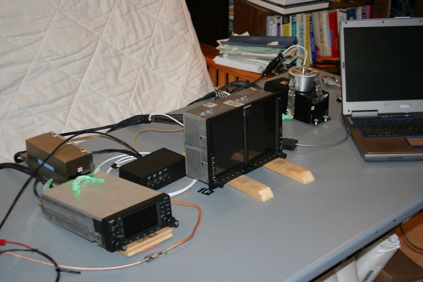
G500 Aviation Incident Handling

                               GIAC (GCIH) Gold Certification

                      Author: Marc Panet-Raymond, mpr.yvo@gmail.com
                                   Advisor: Rob Vandenbrink

                                           Accepted:
                                       February 12, 2014

                                            Abstract
    As airplane cockpits becomes more automated and computerized, will airplane equipment
 manufacturers learn the history lessons of computer security? How does a popular Primary Flight
  Display, the Garmin G500 system, survive when examined from the SANS Hacker Techniques,
Exploits and Incident Handling point of view? It turns out the G500 system survived with no major
   security flaws. However, the G500 system does reveal a lot of information when examined.
G500 Aviation Incident Handling | 2 “Comms system used in the aviation industry contains no security, researcher says.” (Goodin, 2014). “Until now, smart devices have been limited — unable to communicate with onboard systems. Aspen’s new Connected Panel™ technology creates a managed wireless link between your smart devices and certified panel-mounted avionics.” (Aspen Avionics, 2014). Introduction For the safety of the flying public, the majority of security research does not directly target the primary flight instruments. That is, no attempt has been made to disrupt the pilot's primary capability to fly the airplane. The targets are usually airplane supporting systems that can still disrupt the pilot’s navigation duties (Teso, 2013). Is this risk changing? The Aspen Connected Panel allows a pilot to use his uncertified device to communicate wirelessly with a certified primary flight instrument. The only built in safety mechanism is the pilot has to acknowledge the upload of the flight information into the primary flight instruments (Aspen Avionics, 2014). How soon will the primary flight instruments become part of the network? As more and more of the cockpit tasks becomes automated, integrated and computerized will the pilot lose the knowledge to fly the airplane without this help? It is now common to see General Aviation (GA) pilots using Ipads and flight automation software to prepare and monitor parts of their flight. With this trend, are pilots losing basic flying skills to handle the loss of cockpit automation and continue to fly the airplane using the basic flight instruments required as backup to the automation? Today pilots no longer manually calculate distances and time to checkpoints because even the most basic GPS displays this information in real time. As an amateur pilot, I have not manually calculated this type of information in over ten years. Given the vast scope of the current wave of aviation automation, this paper has selected a specific piece of avionics equipment that pilots rely on heavily during flight; the primary flight display (PFD). The PFD is an evolution of the traditional cockpit flight instruments used in all period of the flight. These Marc Panet-Raymond, mpr.yvo@gmail.com
G500 Aviation Incident Handling | 3

instruments are the main indicators for the pilot of where his/her airplane is currently located in the air.
The PFD or the main cockpit flight instruments are especially important when the flight is conducted
under Instrument flight rules (IFR). That is, a flight that is conducted in clouds so the pilot has no
outside reference points to fly the airplane.

A PFD (Federal Aviation Administration, 2014) usually consists of at least a display mounted in the
cockpit and other supporting equipment that is located elsewhere. This supporting equipment usually
consists of an integrated or remote computer. If a computer is used, did the manufacturer take steps to
secure the computer?

The initial idea for this paper was developed after reading a review on a PFD system that was available
with wireless data access. The original idea was to analyze the ethernet traffic and use this information
to determine the security posture of the device. The idea was to leverage the wireless access to
determine if it could be used to compromise a PFD system.

Is there a computer security risk using an electronic PFD? The following research will determine the
security posture of a PFD used primarily for General Aviation (GA) airplanes. For this research, the
number of devices was reduced to two main PFDs: the Garmin G500 and the Aspen Avionics
Evolution 1000. The Aspen Evolution's main feature is the ease of installation and low cost. It also
has the option of the “Connected panel” which allows the pilot to enter flight information wirelessly.
The Garmin G500 is a more advanced system, with optional components not including wireless access.
However, it is more costly and difficult to install. Working with a local consulting firm and a friendly
avionics shop a new Garmin G500 would be loaned for research and testing. Since the consulting firm
planned to install the G500 system into a certified airplane after the evaluation, the warranty terms
needed to be respected. Therefore the system units was not taken apart and the research and testing
focused on using a black box approach.

1.1 Aviation terminology
In order to understand the aviation terminology of this research a few terms need to be defined and
explained. Each country has a certain administrational responsibility for aviation, within the
guidelines, set by the International Civil Aviation Organization (ICAO). In the United States, it is the
Federal Aviation Administration (FAA) and in Canada it is Transport Canada (TC).

Marc Panet-Raymond, mpr.yvo@gmail.com
G500 Aviation Incident Handling | 4

The first decision is to narrow the aviation segment we are targeting. We will be examining civil
aviation (Civil Aviation, 2014), that is all non-military aviation. Civil aviation is then further sub
divided into scheduled air transport (the airlines) and general aviation. (Secretariat, 2014). General
aviation can also be further divided into commercial and private aviation. Commercial aviation
represents flights that are for hire, that is, the passenger pays for the flight. Private aviation are flights
that are taken by private individuals and companies where the pilot is not paid directly for flying the
airplane. Private aviation will be our main focus.

The next definition are the airplane flying rules. The first of two main categories are the visual flight
rules (VFR) (Federal Aviation Administration, 2014). VFR are the regulations that allows a pilot to fly
the airplane with reference to what he sees outside the cockpit. That is the pilot has to see where he is
going and avoid all other airplanes and obstacles if he is flying VFR. When flying VFR you are not
allowed to enter into clouds.

When the weather does not allow for the pilot to see outside the cockpit he will have to fly by
instrument flight rules (IFR) (Federal Aviation Administration, 2014).        That is the pilot is flying the
airplane without looking outside the window. Flying IFR the pilot is only using his cockpit flight
instruments to fly the airplane. In addition, the airplane is also required to be certified for IFR flight.
The FAA and TC, define a minimum equipment list that is required to fly VFR and IFR. Federal
Aviation Regulations (FAR), FAR 91.205(a), (US Government Printing Office, 2014), defines the
minimum equipment required for VFR flight: airspeed indicator, altimeter, compass, tachometer, oil
pressure gauge, fuel gauge, landing gear position indicator, if equipped with a retractable landing gear.
For IFR flight you also require: a two way radio, gyroscopic rate-of-turn indicator, slip-skid indicator,
sensitive altimeter adjustable for barometric pressure, a clock displaying hours, minutes and seconds,
gyroscopic pitch and bank indicator (artificial horizon), gyroscopic direction indicator or directional
gyro (DG).

The PFD is able to replace a majority of minimum required instruments for IFR flight into a central
display controlled by various sensors including a type of computer. Since the PFD replaces various
instruments how do you handle a failure of the PFD.? Regulations (Garmin, 2014) have defined the
required standby instruments: the artificial horizon, the airspeed indicator and the altimeter. These
standby instruments are usually relocated beside the PFD so they can be used in case of failure of the
PFD. To ensure the pilot is able to handle a failure situation, most continuing education programs

Marc Panet-Raymond, mpr.yvo@gmail.com
G500 Aviation Incident Handling | 5

incorporate a form of “partial panel” review training.

These definitions are only meant to introduce the subject, to assist the reader, and not meant to be
precise or to be used as reference.

1.2 The Garmin G500

The Garmin G500 system contains five separate components: the GDU 620, the GRS77, the GMU 44,
the GTP 59 and the GDC 74A (Garmin, System Overview, 2012). The GDU is the main display
system consisting of two built in side by side VGA 6.5 inch displays. We will use the term GDU and
display interchangeably. The left display serves as the PFD showing primary flight information. The
right display serves as the multi-function displays (MFD) showing navigation and other related
information. The GRS system is the attitude and heading reference system (AHRS) containing
advanced tilt sensors, accelerometers and rate sensors. The GMU is the magnetometer sensor used to
determine magnetic heading of the airplane. The GTP is the outside air temperature probe (OAT). The
GDC is the air data computer that uses the airplane pitot static system, outside air temperature and
information from the other units to determine airspeed, vertical speed and pressure altitude for display.

In addition there are various optional units, including the GAD 43, an adapter to interface to the
airplane autopilot. This unit was not used during this research. The G500 is also designed to be able
to display other information of interest to the pilot through optional add on units. These units can
display satellite weather information, traffic information and satellite music. Also not included in this
research is the optional software package for synthetic vision. Synthetic vision uses a GPS database to
display for the pilot a virtual terrain map. The main goal of synthetic vision is to improve the pilot's
situational awareness under IFR flight. The G500 system also requires a compatible GPS navigator to
operate that is not part of the G500 system and is sold and installed separately.

In figure 1.2.1 shown below, are the main logical interface data paths for the G500 system.

Marc Panet-Raymond, mpr.yvo@gmail.com
G500 Aviation Incident Handling | 6

                                Equipment Installed per this STC
        Adapter (optional)       to Autopilot
            GAD 43

          Magnetometer
            GMU 44                                                                      Electric
                                                                                        Standby
                                                                                       Attitude***
                 AHRS                  PFD/MFD Display
                GRS 77                                                                 (optional)
                                          GDU 620
        Air Data Computer
             GDC 74()

       Temperature Probe
           GTP 59

                                                                              Audio Panel
  No. 1 GPS/SBAS Navigator                                                    (optional)**
          (required)
                                                                                  Traffic
                                                                                (optional)
  No. 2 GPS/SBAS Navigator
          (optional)                                                    XM WX/Entertainment
                                                                           GDL 69/69A
                                                                            (optional)
    No. 1 VOR/Localizer/GS
           (optional)                                                        Weather Radar
                                                                               (optional)

    No. 2 VOR/Localizer/GS                                                  Radar Altimeter
           (optional)                                                         (optional)

                                                                            Iridium Data Link
    Autopilot/Flight Director                                                    (optional)
           (optional)
                                                                              Video Source
             ADF                                                                (optional)
           (optional)

                                                                   *Standby Attitude: may be replaced
                                  Existing Equipment
                                 (already installed in aircraft)   with electric attitude indicator with
                                                                   integral / dedicated backup battery.
    Standby        Standby
    Airspeed       Attitude*                                       **Audio panel connection to GDU 620
                                                                   is recommended for tones and aural
                                                                   alerts generated by the GDU 620.
                                                                   This MUST be connected if TAWS
                                                                   and/or SVT is enabled.
    Standby        Magnetic
    Altimeter      Compass
                                                                   *** Installation of the Mid-Continent
                                                                   electric standby attitude indicator is
          (required)                                               approved by this STC.

                                Figure 1.2.1 G500 logical data paths (Garmin, 2014).

The G500 uses various databases that are stored internally and on SD cards in the unit’s two SD slots.
The database information needs to be inserted into the bottom slot of the GDU (Garmin, 2012). The
base map database provides ground based references such as roads and bodies of water. This
information is stored in the internal memory of the GDU. Garmin will provide details on how to load
the updated data since this information changes infrequently. The navigation database is required
information for flight planning. This database is updated frequently and downloaded into the unit via
the top slot. The database updates are specified for one unit. The Flitecharts, Chartview and Safetaxi

Marc Panet-Raymond, mpr.yvo@gmail.com
G500 Aviation Incident Handling | 7 databases are used primarily for IFR flight and are also updated frequently. The terrain, airport terrain, and obstacles databases are used to provide obstacle and terrain warnings to the pilot through the GDU. This information is also updated frequently. The last database is the international geomagnetic reference field (IGRF) model that is used by the GRS77 unit and is updated every five years. No procedure is given to update this database. After having selected the G500 system the local airplane maintenance facility was informed that a G500 system could not be purchased without being installed into a certified aircraft. After discussion with the avionics shop the G500 was purchased for educational purposes. The documentation stated that the unit could not be installed into an airplane. After this research, the appropriate aviation documentation will have to be updated to ensure airworthiness, FAA form 8130-3 Authorized Release Certificate, for installation by an authorized Garmin dealer. The next challenge was how to simulate an airplane environment on a lab bench. With advice from the avionics shop a custom wiring harness was fabricated for the lab. The next step was to perform a magnetic interference survey to calibrate the new G500. The avionics shop was unsuccessful in re- using an existing results file to calibrate the new G500. To perform the magnetic interference survey an existing airplane with a G500 was found and its components were replaced with the new G500 and the calibration performed. An appropriate GPS navigator is required for the G500 system to be complete. A loaner GPS navigator, with an antenna assembly, and a bench power supply was obtained. Prior to leaving the avionics facility basic operation of the system was confirmed. Lab research was now ready to start. Marc Panet-Raymond, mpr.yvo@gmail.com
G500 Aviation Incident Handling | 8

                                       Figure 1.2.2: Lab setup
The majority of the G500 components can be seen in figure 1.2.2. Starting at the bottom left and going
clockwise. The Garmin GPS, the GDC air computer, a fuse box, the GDU display, and the AHRS with
the GMU taped on top. In addition you can notice the custom wiring harness required to connect all
the components.

Marc Panet-Raymond, mpr.yvo@gmail.com
G500 Aviation Incident Handling | 9 G500 Aviation Incident Handling 2.1 Preparation Similar to incident handling an airplane flight starts with the planning phase. Prior to arriving at the airport on the day of the flight, the pilot has completely planned out their flight. The planning process starts by the pilot selecting a route from departure to destination. Under IFR flight there may be preferred routing that has to be taken into consideration (Nav Canada, Jan 02, 2014). Notices to Airmen (NOTAMs) are consulted indicating any last minute changes to procedures and documentation, FAR 91.139, (US Government Printing Office, 2014). In a worst case scenario, the pilot may have to change their destination, if for example there is a NOTAM closing the only destination runway. In addition, the weather forecasts are consulted for the duration of the flight. A cautious pilot will also look at the weather forecast for the time period prior and after the flight to try to determine weather trends. If the flight is IFR, the pilot needs to choose an alternate airport close by that is scheduled to have better weather than their destination. This is done, by regulations, to ensure the pilot has enough fuel to attempt a landing at their destination, execute a missed approach due to bad weather, and land safely at the alternate airport, FAR 91.169, (US Government Printing Office, 2014). Various software tools are available to assist the pilot in this planning process. Once the flight planning step has completed the pilot has a “baseline” of their flight. For example, the flight time required, the fuel required, the air traffic control (ATC) sectors, and the navigation aids required. The more the pilot is familiar with all the required information, the easier he will be able to detect a deviation from the normal state, FAR 91.103, (US Government Printing Office, 2014) Similar to incident handling the pilot is constantly evaluating events during the flight. For example, as the airplane is flying towards the destination, the pilot will be talking to different ATC sectors. During each initial communication with a new ATC sector the pilot states, at least, their call sign, altitude and location if not under radar contact (Jeppesen, 1998). This is to ensure that ATC and the pilot can validate each other’s information. If for example, the pilot is not able to contact ATC, there is a procedure in place to allow the pilot to continue the flight, as filed or the last clearance given, to the destination (Nav Canada, Jan 02, 2014). On the day of the flight the last step prior to getting into the airplane is the airplane pre-flight. The pre- Marc Panet-Raymond, mpr.yvo@gmail.com
G500 Aviation Incident Handling | 10

flight is done by all pilots, from the amateur to the airline pilots. A pre-flight consists of hands on
verification of the airplane. The pilot starts at a given location and walks around the airplane checking
numerous systems. For example, on a small GA airplane, the pilot starts at the passenger door. At lot
of GA airplanes only have one door and it is located on the right side, looking forward, the passenger
door since the pilot sits on the left hand side (Mooney Aircraft Inc., 1966). From this point he goes to
the tail of the airplane checking the static ports, used by the PFD to determine airspeed and altitude
among other variables. He then physical moves the rudder and elevators to ensure free movement.
During the walk around he also looks to see if there is anything out of the ordinary that would cause the
flight to be cancelled. He continues the pre-flight check by examining the wings; the flaps, ailerons,
the fuel level, pitot tube, stall warning device and other flight related items. He then examines the
propeller and engine intake area. Most airplanes have a maintenance opening to allow verification of
the oil level and other engine items. He then continues and verifies the second wing before ending up
where he began.

Once comfortably seated in the cockpit, having adjusted the seat and seat belts, the pilot takes out his
checklist and starts the first of four main sections (Mooney Aircraft Inc., 1966): pre-engine start,
engine start, pre-taxi, run up and pre-takeoff. As with the pre-flight if any of the items does not appears
correct the pilot will have to decide if the anomaly needs to be corrected prior to continuing. Without
going into details, each airplane system is checked and verified to ensure it is ready for a safe flight.
Depending on the size of the departure airport the pilot may use the airplane radios to establish contact
and ask for permission to taxi to the active runway. This is normal procedure and is part of the
checklist.

2.2 Identification

Once the airplane is ready to begin the flight, the preparation phase has terminated and he moves on to
the identification phase to ensure a safe flight. He communicates his intention to proceed to the active
runway either by obtaining permission or by broadcasting on the advisory frequency. He then verifies
he is indeed on the correct runway by double checking the runway selected with the magnetic compass
and the DG. For example runway 18, is the runway facing south, 180 degrees. Once he begins his take
off roll he ensures his airspeed comes alive and all engine instruments are reading in the green. If any
condition is suspect, he can abort before the half way point of the runway. After that point he is

Marc Panet-Raymond, mpr.yvo@gmail.com
G500 Aviation Incident Handling | 11

committed to the takeoff.

Generally you need a certain amount visibility to be able to take off even for an IFR flight. Therefore
once airborne, if IFR, you will then transition to your cockpit instruments and not look outside. Once
you transitioned to instruments, you constantly double check your situational awareness using the PFD
and the other cockpit instruments. Every so often you will also compare the results with the backup
instruments. If any instrument is not satisfactory, the pilot will determine a course of action, if
required. If the airplane is equipped with an autopilot, it may be used to do the flying with the pilot
ensuring all readouts are normal.

2.3 Containment

If there is a catastrophic failure of the PFD the pilot may have to fly the airplane with the backup
instruments. This could be viewed as partial panel flying. This type of flying, under partial panel, is
part of a good training program pilots need to follow (Jeppesen, 1998). Containment for the pilot,
given a failure may be ignoring the PFD and using the backup instruments to complete the flight. The
pilot’s priorities are to aviate, navigate and communicate (Hirschman, 2014). Once safely on the
ground the pilot would notify the maintenance facility of the failure. In the majority of cases the PFD
unit would be returned to the manufacturer for repair for eradication and recovery.

Recently, a Garmin service advisory, No. 1361, dated October 23, 2013, was issued informing pilots
there is a possibility that under certain conditions the AHRS will loss heading information under
certain conditions. This is displayed through a big red X where the heading information is displayed on
the GDU (Garmin, 2014). To correct the problem, a Garmin service bulletin, 1367, dated 19
December, 2013, was issued to correct the problem. It is a mandatory software update performed
under warranty (Garmin , 2014).

2.4 Attack phase

A black box approach was taken for attack testing the G500 system since we do not have any previous
knowledge. The testing methodology followed was the SANS 504 Hacker techniques, exploits and
incident handling; reconnaissance, scanning, exploit systems, keeping access and covering the tracks

Marc Panet-Raymond, mpr.yvo@gmail.com
G500 Aviation Incident Handling | 12

(SANS Institute, 2011).

2.4.1 Reconnaissance

The first step was reconnaissance, to determine what kinds of public information was available and
would be useful for evaluation of the G500. Since this research did not target a network or consist of a
penetration test, the approach was tailored to targeting an embedded device system. Using Google, a
copy of the G500 installation manual was found (Garmin, 2014). This manual describes, in details, the
steps required to install the G500 into an airplane and a high level overview of the system. The G500
logical paths, figure 1.2.1, taken from the installation manual, describes the protocols used by the G500
system. The main protocol used by the G500 is ARINC 429. This protocol is also used by most
commercial transport aircraft including Airbus and Boeing (GE intelligent Platforms, 2014). In
addition, the G500 uses RS-232 and various other supporting protocols to communicate with existing
cockpit instruments.

2.4.2 Scanning

The next step in the process is scanning. The scanning process was divided into four main parts;
powering up the system, the SD card slots, the button interface and the I/O paths.

Unlike a computer system the G500 system performs numerous functional integrity checks during
power up. If any of the required components or communication paths are missing the information is
shown to the pilot on the GDU display. These functional integrity checks continue to be performed
during flight to inform the pilot if a portion of the system has failed.

As shown in figure 2.4.2.1 below, airspeed, heading, GPS, and altitude have failed integrity tests.

Marc Panet-Raymond, mpr.yvo@gmail.com
G500 Aviation Incident Handling | 13

                                   Figure 2.4.2.1: Failure indications
In addition, during power up the system ensures the databases are current and are safe to use for
navigation. The next data path examined is the button interface. As shown on figure 2.4.2.1 above the
GDU shown has eight dedicated buttons, 10 soft keys, one rocker button and two knobs. According to
the G500 installation manual pressing and holding the ENT button while applying power will put the
unit into configuration mode. If pressing and holding the ENT button puts the device into
configuration mode, do any other buttons have undocumented features. The following buttons were
discovered to have undocumented features. The HDG button allowed you to reload the field-
programmable gate array (FPGA). This action reloads both the main FPGA and the IO FPGA. A
possible hypothesis is this button is used to restore the factory setting if an upgrade has encountered
problems. What are the roles of the main and IO FPGA? Pressing the BARO button appears to set the
G500 to Kansas, the location of Garmin. Pressing he CLR button, or the fourth button on the bottom
right of the right screen, allows you to clear all user settings on the device.

Pressing and holding the ENT button puts the GDU into configuration mode allowing the user to view
the configuration information. In order to edit the configuration information a dealer unlock SD card
is required to be present in the bottom slot. The dealer unlock SD card will be discussed in further
detail in the next section.

Marc Panet-Raymond, mpr.yvo@gmail.com
G500 Aviation Incident Handling | 14
The configuration mode can have up to six main pages, depending on equipment installed; system
configuration, GRS (AHRS) configuration, GDC (air data computer) configuration, diagnostics page.
For the purpose of this research the diagnostics page will be our main focus. The diagnostics pages has
several subpages; port monitoring, input monitoring, outputs page and the error log page.
Another feature discovered on the error log page if the dealer unlock card is present you are able to
save the G500 log files to an external SD card. The log file, soft key, button creates a zip file called
UNIT_DATA_GDU_1.zip that is saved to a SD card in the upper slot. This zip file successfully unzips
to two files UNIT_DATA.gca and Description.ini. The UNIT_DATA.gca file was renamed to
UNIT_DATA.zip so the unzip command does not complain about the file extension. Once renamed,
unzip only complains about an error 99. This unusual error message means that it was unsuccessful in
extracting due to password protection. fcrackzip was used to attempted to crack the zip file. The
zip file was unsuccessfully cracked using a 15 GB dictionary file. This indicates that Garmin did not
use a common dictionary word to password protect the zip file.
Even though the file was not cracked, we do see the contents, along with the unusual error message.
Archive: UNIT_DATA.zip
skipping: Description.ini unsupported compression method 99
skipping: eeprom1 unsupported compression method 99
skipping: eeprom2 unsupported compression method 99
skipping: eeprom3 unsupported compression method 99
skipping: err_rpt.dat unsupported compression method 99
skipping: reg_exc_log.reg unsupported compression method 99
skipping: reg_krnl.reg unsupported compression method 99
skipping: reg_lvl_b.reg unsupported compression method 99
skipping: reg_lvl_c.reg unsupported compression method 99
skipping: reg_lvl_d.reg unsupported compression method 99
skipping: reg_prof.reg unsupported compression method 99
skipping: reg_sys_cnfg.reg unsupported compression method 99
skipping: reg_unit_stats.reg unsupported compression method 99
As can be inferred, the information contained in the zip file appears to be low level configuration
information: kernel registers, exception logs, system configuration and unit statistics. The second file,
Description.ini, is a text file with the following contents.
[GDU_620]
Software_Version=6.11
System_ID=13xxxxxx5
Serial_Number=16xxxxx3
CDU_ID=GDU1
Power_Cycle=195
Power_Hours=18.2856
Date_Time=____-__-__ __:__:__
Marc Panet-Raymond, mpr.yvo@gmail.comG500 Aviation Incident Handling | 15
This file appears to contain basic statistics along with a description of the unit. It is interesting to note
the system keeps track of the number of power cycles and time used.
Future research can be done on the button interface using combination of button to explore other
undocumented features.
The next data path explored were the two SD slots: according to the G500 pilots guide the top slot is
used for the navigation database update cards while the bottom slot is used for the terrain, obstacles,
airports, Safetaxi and charts databases. The G500 installation manual, used by Garmin dealers, states
the top slot is used by the loader card that contains the software to update the unit. The lower slot is
used for the dealer installer unlock card. Both the loader card and the dealer unlock card are only
available to Garmin dealers and are specific to each device using the units serial number. A dealer
unlock card and the loader SD card were examined. Examining these cards was done to determine if
Garmin was relying on the restricted access as their security model.
The data contained on each card, dealer unlock card and dealer loader card, was copied onto a Linux
system for analysis. The following steps were used during analysis for each card.
• Directory layout examination and analysis
• File name analysis
• Linux file command
• Linux strings command
• Linux readelf command
The first SD card examined was the dealer unlock card. It only contained three files.
-rwxr-xr-x 1 test test 573 Nov 1 15:19 airframe_info.xml
-r-xr-xr-x 1 test test 913 Nov 1 15:19 feat_unlk.dat
-rwxr-xr-x 1 test test 7174 Nov 1 15:19 phonebook.reg
The first file appears to be an XML description file.
Unknown Aircraft
006-B1071-4B
6.11
13xxxxx5
0x0FFFFFFF
Marc Panet-Raymond, mpr.yvo@gmail.comG500 Aviation Incident Handling | 16 The second file appears to be a feature unlock file that may or may not contain software enabled optional features, such as the synthetic vision. It appears to be a sparse file that looks like depending on options purchased an appropriate code is written into the sparse matrix. $ cat feat_unlk.dat | xxd 0000000: 0100 3301 9a32 4876 0002 0000 0000 0000 ..3..2Hv........ 0000010: 310c bbdb 0000 0000 0000 0000 0000 0000 1............... 0000020: 0000 0000 0000 0000 0000 0000 0000 0000 ................ 0000030: 0000 002a 5634 6000 0000 0000 0000 0000 ...*V4`......... 0000040: 0000 0000 0000 0000 0000 0000 0000 0000 ................ 0000050: 00d5 20ce 4300 0000 0000 0000 0000 0000 .. .C........... 0000060: 0000 0000 0000 0000 0000 0000 0000 0000 ................ ... nulls 0000360: 0000 0000 0000 0000 0000 0000 0000 0000 ................ 0000370: 0000 0000 0000 0000 0000 0000 0000 0000 ................ 0000380: 0000 0000 0000 0000 0045 6bb6 1e93 b8d8 .........Ek..... 0000390: a0 . The third file is similar type of format to the feature unlock file but unsure of its purpose. $ cat phonebook.reg| xxd 0000000: 8000 0000 1200 0000 0000 2800 0040 5046 ..........(..@PF 0000010: 0000 0000 5aa0 0000 0000 0000 0000 0000 ....Z........... 0000020: 0000 0000 0000 0000 0000 0000 0000 0000 ................ 0000030: 0000 0000 0000 0000 0000 0000 0000 0000 ................ 0000040: 0000 2800 0040 5146 0000 0000 5aa0 0000 ..(..@QF....Z... 0000050: 0000 0000 0000 0000 0000 0000 0000 0000 ................ 0000060: 0000 0000 0000 0000 0000 0000 0000 0000 ................ 0000070: 0000 0000 0000 0000 0000 2800 0040 5246 ..........(..@RF 0000080: 0000 0000 5aa0 0000 0000 0000 0000 0000 ....Z........... 0000090: 0000 0000 0000 0000 0000 0000 0000 0000 ................ 00000a0: 0000 0000 0000 0000 0000 0000 0000 0000 ................ 00000b0: 0000 2800 0040 5346 0000 0000 5aa0 0000 ..(..@SF....Z... 00000c0: 0000 0000 0000 0000 0000 0000 0000 0000 ................ 00000d0: 0000 0000 0000 0000 0000 0000 0000 0000 ................ 00000e0: 0000 0000 0000 0000 0000 2800 0040 5446 ..........(..@TF 00000f0: 0000 0000 5aa0 0000 0000 0000 0000 0000 ....Z........... 0000100: 0000 0000 0000 0000 0000 0000 0000 0000 ................ 0000110: 0000 0000 0000 0000 0000 0000 0000 0000 ................ 0000120: 0000 2800 0040 5546 0000 0000 5aa0 0000 ..(..@UF....Z... ...similar repeating data The second card examined was the dealer loader card. It contained the following files: drwxr-xr-x 4 test test 4096 Nov 18 12:09 ldr_sys -rwxr-xr-x 1 test test 573 Nov 1 15:22 airframe_info.xml -rwxr-xr-x 1 test test 639472 Nov 1 15:22 file.rgn -rwxr-xr-x 1 test test 33 Nov 1 15:22 ldr_part_nmbr.txt -rwxr-xr-x 1 test test 7174 Nov 1 15:22 phonebook.reg -rwxr-xr-x 1 test test 116 Nov 1 15:22 sw_ldr.nfo -rwxr-xr-x 1 test test 857600 Nov 1 15:22 SYS_KRNL.bin The airframe_info.xml file is the identical file to the dealer unlock card describing the installed airframe. In this case the system has not been installed into an airplane and thus states unknown. Marc Panet-Raymond, mpr.yvo@gmail.com
G500 Aviation Incident Handling | 17

The file.rgn is a binary file unsure to its purpose. Below is a snippet of the 430 lines of string
information. It appears to be configuration or calibration type information.
$ strings -n 10 file.rgn
(c) 2012, GARMIN Ltd. or subs
GRS77 VER 3.03
006-B0223-23
a(j b(h``hh
@cal_main.c
stn %i: meas: h=%8.6f v=%8.6f mean: h=%8.6f v=%8.6f           igrf: h=%8.6f v=%8.6f
SITE IS CLEAN
MAG FIELD AT SITE NOT UNIFORM
MAG FIELD AT SITE DIFFERS FROM IGRF MODEL
SITE IS NOT QUALIFIED YET
nvm_intf.c
nvm_main.c
Accelrmtr CALIB
Accelermtr NOT CALIB
  temp bias %6.4f %6.4f %6.4f
  vltg bias %6.4f %6.4f %6.4f
Gyros CALIB
Gyros NOT CALIB
006-C0049-00
GRS77 XILINX
(c) 2012, GARMIN Ltd. or subs
GDC74 VER 3.09

The ldr_part_nmbr.txt file appears to contain the G500 part number information. It is only a 3
line text file. The sw_ldr.nfo file appears to contain GDU620 part number information along with
some binary information. The binary information is all nulls except for a 0x04 value. The
SYS_KRNL.bin file contains over 6000 string symbols including the airframe xml definition from
above. The Linux file command did not recognize the file type. A portion of the strings output is
shown below.

    %s
    %s
    %s
    %s
    %lX%08lX
    0x%08lX

       %s
       %s

/dont_gen_airframe_info
/airframe_info.xml
...
/mnt/sys_nand0/atm_struct.bin
/sys_nand0
/mnt/sys_nand0
/mnt/card0
/mnt/sys_nand0/phonebook.reg
/dev/sd_card0
/mnt/card0/dbg_printf.txt
Do you want to reset to FACTORY DEFAULTS?
/dev/eeprom1

Marc Panet-Raymond, mpr.yvo@gmail.com
G500 Aviation Incident Handling | 18 The ldr_sys directory contained the following files: FPGA_io.bin resources SYS_CDP_EIS.exe SYS_CDP_PFD.exe SYS_CDP_TEST.exe SYS_IOP_B.exe SYS_IOP_D.exe SYS_LOG.exe SYS_MPM.exe FPGA_main.bin SYS_CDP_CONFIG.exe SYS_CDP_MFD.exe SYS_CDP_PWRP.exe SYS_CHT_MAIN.exe SYS_IOP_C.exe SYS_IOP_SIM.exe SYS_M3D.exe SYS_TWS.exe lib SYS_CDP_DEVNFO.exe SYS_CDP_MNGR.exe SYS_CDP_SKEY.exe SYS_DSC.exe SYS_IOP_CIFS.exe SYS_KRNL.bin SYS_MDB.exe valid_lrus.ini The .bin files were not recognized but the .exe files were. $ file SYS_LOG.exe SYS_LOG.exe: ELF 32-bit LSB executable, ARM, version 1 (SYSV), statically linked, stripped The lib directory contained one file the appeared to the Linux file command similar to the .exe files listed above: -rwxr-xr-x 1 test test 479036 Nov 1 15:22 SYS_RESOURCE.dll The resources directory contained the following: adf1_arrow.tga_crc dash_line.tga_crc Horizon Side Mark.tga Obstacle Short Unlit.tga std_hsi_compass.tga_crc adf2_arrow.tga_crc dash_line_wide_opaque.tga_crc hrzn_labels.tga_crc Obstacle Tall ... std_hsi_arrow.tga_crc vspd_indicator_red.tga_crc dash_line_opaque.tga_crc Horizon Center Mark.tga Obstacle Short Lit.tga std_hsi_compass_no_card.tga_crc vspd_indicator.tga_crc All these 85 files appear to be image files. A sample of the readelf command output is listed below. It appears that the .dll and .exe files are ARM executables. This potentially helps identify the internal system architecture. How does this information correlate to the FPGA files seen? $ readelf -a SYS_RESOURCE.dll ELF Header: Magic: 7f 45 4c 46 01 01 01 00 00 00 00 00 00 00 00 00 Class: ELF32 Data: 2's complement, little endian Version: 1 (current) OS/ABI: UNIX - System V ABI Version: 0 Type: EXEC (Executable file) Machine: ARM Version: 0x1 Entry point address: 0x400040b8 Start of program headers: 478808 (bytes into file) Start of section headers: 478872 (bytes into file) Flags: 0x200001e, has entry point, Version2 EABI, The last major section was to attempt to read, sniff, the communication paths between the units. The three main protocols used by the G500 are ethernet, ARINC 429 and RS-232. Initially it appeared that Marc Panet-Raymond, mpr.yvo@gmail.com
G500 Aviation Incident Handling | 19

ethernet would be an easy method communication path to use but upon further research it was
determined that Garmin uses its own proprietary format, the high speed data bus (HSDB) and it is only
used to communicate with the optional GWX 68, weather radar unit. ARINC 429 is a protocol
developed especially for the aviation industry. It is a well-defined and documented data transfer
protocol. This protocol looked promising after the disappointment of not being able to take advantage
of ethernet knowledge. After some initial research this avenue was deemed too specialized and costly
to examine.

The next possible protocol was the RS-232 protocol. Using the provided custom wiring harness I
proceeded to see if there was data on the wire. The initial step was connecting an old laptop with a RS-
232 port to the wiring harness using the appropriate connectors and adapters. Once completed the
minicom Linux terminal communication program was used to verify communication settings, such
as baud rate and parity. Once corrected, data began to appear. None of the data appearing on the
screen was readable and thus assumed to be binary. Even if the data was not readable, it arrived at
uneven lengths and different time intervals.

The wiring harness provided three different RS-232 data paths to examine. We decided to focus on
the provided wiring harness access to the air data computer, the GDC, to the GDU to determine the
security posture of the computer.

At this point the following steps were applied to try and analyze the data.
   •   Examine stream to determine if there are packets.
   •   The packets were sorted and tried to determine if there was any repetition or differences.
   •   Conversely, after sorting the packets were examined to determine how the packets change.

To be able to save the data stream for analysis a python program was created to capture the data.     The
first version of the program captured the binary data and converted the data to printable hex values.
The next version added the conversion to decimal to assist in analysis. After a certain amount of time
analyzing, no protocol was evident. The next step was to add a timestamp to the data stream to see if
any pattern would emerge. With the added timestamp it became clear there were defined intervals.
Examining the stream at the defined intervals it was easy to see the start and end of a packet. The only
exception is on power initialization the following data stream is sent.

Marc Panet-Raymond, mpr.yvo@gmail.com
G500 Aviation Incident Handling | 20

0x0 0x40 0x0 0x80 0xa5

The next step was to examine one record and determine what data is represented. Since the G500 is
compatible with the G400 series GPS it was hypothesised that the RS-232 would use the Aviation Data
Format (Garmin, 2001). After examination of the packet it does not appear the G500 uses the same
Aviation Data Format for RS-232 communications. An obvious difference, to the Aviation Data
Format, is the captured packet contained almost 50% nulls. Does this mean that certain portions of the
record are fixed and the null are used as place holders as in the ARINC 429 protocol (GE Intelligent
Platforms, 2014)? Similar to a game of Scrabble, different ways of looking at the data were tried to
determine if any sensible information is represented. It was not determined how the RS-232 stream is
used in conjunction with the ARINC 429 stream to communicate with the GDU.

Since just examining one packet did not reveal any information, two scenarios were used to determine
if a different response could be observed to assist in decoding the packet. The scenarios listed below
were used due to the difficulty in taking the lab setup into either an automobile or an airplane to
simulate movement. The first scenario was reading the data stream while the GPS attempting to obtain
a fix. This process takes about 2 minutes until the GPS is able to determine its present position. Once
a fix was obtained an additional time was left to ensure the data stream had stabilized. At this point the
RS-232 stream was stopped.

The second scenario was to put the GPS into demo mode. This mode is obtained by grounding a
particular pin during power initialization of the GPS. The demo mode allows you to simulate portions
of a flight without having to move your physical location. It also allows you to set the location,
altitude, the ground speed (vs IAS, TAS), etc. The demo mode allows you to define a starting and
destination point. These locations are defined by specifying the latitude and longitude. Once defined
the altitude and ground speed are given prior to pressing start soft key on the GPS navigator. Having
defined known information we hoped this would help to decode the RS-232 data stream.

Using the two data files generated several basic Linux tools were used to assist in the analysis, as
shown below (Green, 2014). The first data file, acquiring a GPS fix, contained 130 packets and after
applying a sort –u filter on the data reduced it to 16 different packets. The second data file
contained 221 packets and after applying a sort –u filter on the data reduced it to 26 different

Marc Panet-Raymond, mpr.yvo@gmail.com
G500 Aviation Incident Handling | 21

packets. The packet length for all packets had various different values from 37 bytes to a maximum of
199 bytes.

The starting point was the stream output with timestamps generated by python program reading the RS-
232 data. The comments are manually added after the data acquisition. The two data files used were
named, demo.log for the demo flight from KBJC to KDEN, and acquire.log for the GPS
acquiring scenario.
Sample of the demo.log file highlight time spacing to determine packet format.
Demo mode position from KBJC, Rocky Mountain Metropolitan airport
  flight plan to KDEN, Denver International airport
Demo movement track: 030 degrees, Ground speed: 150kt, altitude: 9900 feet

2013-12-14   11:15:47,057 - g500-serial-in - INFO - ------start run-----------
2013-12-14   11:15:55,065 - g500-serial-in - INFO - 0x0
…
2013-12-14   11:16:06,376     -   g500-serial-in   -   INFO   -   0x85 0xc4
2013-12-14   11:16:06,379     -   g500-serial-in   -   INFO   -   0xa5 0x0 0x0
2013-12-14   11:16:06,381     -   g500-serial-in   -   INFO   -   0x0 0x0
2013-12-14   11:16:06,384     -   g500-serial-in   -   INFO   -   0x0 0x0
2013-12-14   11:16:06,391     -   g500-serial-in   -   INFO   -   0x4 0x20 0x0 0x3 0x40 0x3 0x1 0x2
2013-12-14   11:16:06,394     -   g500-serial-in   -   INFO   -   0x0
2013-12-14   11:16:06,400     -   g500-serial-in   -   INFO   -   0xc0 0x1 0xf1
2013-12-14   11:16:08,840     -   g500-serial-in   -   INFO   -   0x20
2013-12-14   11:16:08,849     -   g500-serial-in   -   INFO   -   0x1 0xc0 0x82 0x8d 0xa4 0x26 0x84 0x84
2013-12-14   11:16:08,852     -   g500-serial-in   -   INFO   -   0x86 0x4
2013-12-14   11:16:08,855     -   g500-serial-in   -   INFO   -   0x4 0x80 0xe4
2013-12-14   11:16:08,858     -   g500-serial-in   -   INFO   -   0x84 0x0 0x1
2013-12-14   11:16:08,861     -   g500-serial-in   -   INFO   -   0xa1 0x84 0x42
2013-12-14   11:16:08,864     -   g500-serial-in   -   INFO   -   0x42 0x43 0x0
…
2013-12-14   11:16:06,324 - g500-serial-in - INFO - 0xa4

For each file, the following steps were taken to determine any patterns between the two scenarios.
This command took the python generated log file and removed all leading date and time information
and left only the hex data.
$ cat demo.log | cut –d “ “ –f 8-99 > demo.cut
The following python program takes the hex data and generates packets according to well defined
header and trailer information discovered during the initial analysis of the data.
$ python process-log.py demo.cut > demo.pkt
The next step was to create a baseline of all the unique packets. This file is used later on to help define
packet types.
$ cat demo.pkt | sort –u > demo.srt.u
To assist in defining the packets and resorting, line numbers were added to packet file.
$ cat –n demo.pkt > demo.n.pkt
Once line numbers were added the file was sorted using the whole record without the line numbers as

Marc Panet-Raymond, mpr.yvo@gmail.com
G500 Aviation Incident Handling | 22

the key.
$ sort –k 2 demo.n.pkt > demo.n.pkt.srt
This resultant file was then loaded into a spreadsheet to help classify the packets. The demo.srt.u
file was used to help highlight when the packet changed. The use of color greatly eased the task of
keeping track of the packet changes due to the large length of some of the packets. Once a type field
was given to each unique packet, the resultant file was resorted using the line numbers to return the file
to its original order.

The addition of the type field assisted in the analysis of the two data scenario files. As shown in
appendix A, table 1, in the demo.log column, the packet types 7 and 24 repeat regularly. The use of
color is only used to highlight the pattern. Looking at the acquire.log column the same repeating
packet types are found. The only difference between the two scenarios are the other packet types that
are intermingled in each stream. Interesting to note that packet type 27 only appears during GPS
acquisition. Further research is required to fully understand the current findings.

2.4.3 Exploitation

The next step was to see if we can get the system to crash using a buffer overflow scenario. This was
done by writing another python program to give a valid header followed by a configurable number of
nulls to get the system to crash.

After several attempts of up to one million nulls the system did not react in any way. That is no
messages in the diagnostics pages nor any reaction on the main display. Either the system was very
well programmed or the stream was getting to the system. To convert from reading the stream to
writing to the stream we employed a RS-232 adapter that changed the transmission and receive pins.

Since we were not able to exploit the system the subsequent steps on the attack process were not
started.

Marc Panet-Raymond, mpr.yvo@gmail.com
G500 Aviation Incident Handling | 23

Conclusion
Is the PFD secure from the computer point of view? Generally it can be stated the system does not
have any obvious security failures. It was noted that a lot of information was found using simple
methods of information gathering.

A positive discovery was the level of defence in depth used to protect the low level information
contained in the zip file archive. This showed that the manufacturer did not just rely on the fact that the
dealer unlock card should only be available to authorized dealers. A second level of protection was
added by password protecting the zip file with a non-dictionary word. This does not eliminate the risk
of discovering the password since now the attacker needs to brute force the password.

In addition, the G500 system appeared to be handle extraneous input received from the air computer,
the GDC, having successfully handled the buffer overflow attempt. This shows that in addition to the
functional integrity checks performed it appears the data stream input is well validated. This type of
attack required custom wiring to be able to sniff and manipulate the stream that in a real world situation
would not be trivial to perform. However, we were not able to fully determine the purpose of the RS-
232 stream.

However, the areas where further research will determine if the manufacturer has taken appropriate
steps to secure the G500 system is the software and database update and upgrade process. The
software upgrade process is regulated to be performed by authorized maintenance personnel only. The
database update process is usually done by the pilot. In both cases the manufacturer is relying on the
intermediate computer to transfer the data. Further research is needed to determine if the manufacturer
has taken steps to ensure their database data is not vulnerable during the update process.

Marc Panet-Raymond, mpr.yvo@gmail.com
G500 Aviation Incident Handling | 24

Appendix A

 demo.log   acquire.log   demo.log   acquire.log   demo.log   acquire.lo    demo.log   acquire.log
                                                              g
 T1         T1            T7         T24           T7         T24           T24
 T7         T24           T15        T7            T24        T7            T7
 T26        T7            T24        T17           T7         T24           T24
 T24        T24           T7         T24           T24        T27           T7
 T7         T7            T24        T7            T3         T24           T24
 T20        T24           T7         T24           T7         T7            T5
 T24        T7            T24        T7            T24        T24           T7
 T7         T24           T7         T24           T7         T7            T24
 T24        T7            T24        T7            T24        T24           T7
 T7         T17           T7         T24           T2         T7            T21
 T24        T24           T24        T7            T7         T24           T24
 T7         T7            T7         T14           T24        T7            T7
 T24        T24           T24        T24           T7         T24           T13
 T7         T7            T7         T7            T24        T7            T24
 T24        T24           T24        T24           T7                       T8
 T7         T7            T7         T7            T24                      T7
 T21        T23           T24        T24           T7                       T16
 T18        T18           T7         T7            T24                      T24
 T24        T24           T24        T24           T2                       T6
 T7         T7            T7         T7            T7                       T7
 T19        T24           T24        T15           T20                      T24
 T7         T7            T7         T7            T25                      T7
 T24        T24           T24        T24           T24                      T24
 T7         T7            T7         T7            T7                       T7
 T24        T24           T24        T24           T13                      T24
 T7         T6            T7         T7            T24                      T7
 T24        T24           T24        T24           T7                       T16
 T7         T7            T7         T7            T24                      T24
 T17        T24           T24        T24           T7                       T7
 T17        T7            T7         T7            T23                      T24
 T24        T24           T24        T24           T24                      T7
 T2         T7            T7         T7            T7                       T13
 T7         T24           T20        T24           T24                      T24
 T24        T7            T24        T7            T7                       T7
 T7         T24           T7         T24           T24                      T18
 T24        T7            T24        T7            T7                       T24
 T4         T24           T7         T24           T14                      T7

Table 1 – Snippet RS-232 streams with assigned packet types.

Marc Panet-Raymond, mpr.yvo@gmail.com
G500 Aviation Incident Handling | 25
References
Aspen Avionics. (2014, 02 10). Introduction | Connected Panel. Retrieved from Introduction |
Connected Panel: http://www.connectedpanel.com/
Aspen Avionics. (2014). Mobile Device (iPad). In A. Avionics, Connect Panel Pilot's Guide
Supplement (pp. 2-2). Aspen Avionics.
Civil Aviation. (2014, 02 10). Civil Aviation - Transport Canada. Retrieved from Transport Canada:
https://www.tc.gc.ca/eng/civilaviation/menu.htm
Federal Aviation Administration. (2014, 02 10). I. Retrieved from Federal Aviation Administration:
https://www.faa.gov/air_traffic/publications/atpubs/pcg/I.HTM
Federal Aviation Administration. (2014, 02 10). Pilot Handbook of Aeronautical Knowledge. Retrieved
from Federal Aviation Administration:
http://www.faa.gov/regulations_policies/handbooks_manuals/aviation/pilot_handbook/media/P
HAK%20-%20Chapter%2007.pdf
Federal Aviation Administration. (2014, 02 10). V. Retrieved from Federal Aviation Administration:
https://www.faa.gov/air_traffic/publications/atpubs/pcg/V.HTM
Garmin. (2014, 02 08). Service Bulletin 1367. Retrieved from Garmin Blogs:
garmin.blogs.com/aviationalerts/2013/12/service-bulletin-1367-stc-sa02153la-d-g600-system-
new-interfaces-rvsm-and-software-upgrades-for-gdu-.html
Garmin. (2001). Appendix D 400W Series RS-232 Aviation Data Format. In Garmin, 400 Series
Installation Manual (pp. C-1). Olathe KS: Garmin Internation, Inc.
Garmin. (2012). Garmin Databases. In Garmin, G500 Pilot's Guide (pp. A-5). Olathe, KS: Garmin
International, Inc.
Garmin. (2012). System Overview. In Garmin, G500 Pilot's Guide (pp. 1-1 to 1-8). Olathe, KS:
Garmin International, Inc.
Garmin. (2014, 02 10). Required Standby Instruments. In Garmin, G500 AML STC Installation Manual
(pp. 1-6). Olathe KS: Garmin International, Inc. Retrieved from Russian:
http://www.neboservice.ru/docs/0148862001365758294.pdf
Garmin. (2014, 02 08). Service Advisory 1361. Retrieved from Garmin Blog:
http://www8.garmin.com/aviation/notices/1361.pdf
GE Intelligent Platforms. (2014, 02 10). Brochures. Retrieved from GE Intelligent Platforms:
http://psirep.com/system/files/arinc_protocol_tutorial_wp_gft639a_16.pdf?width=900&height=
675&iframe=true
Marc Panet-Raymond, mpr.yvo@gmail.comG500 Aviation Incident Handling | 26
Goodin, D. (2014, 02 10). Hacking commercial aircraft with an Android App (some conditions apply).
Retrieved from ars technica: http://arstechnica.com/security/2013/04/hacking-commercial-
aircraft-with-an-android-app-some-conditions-apply/
Green, T. (2014, 02 10). SANS Institute: Reading Room - Protocols. Retrieved from SANS
Information, Network, Computer Security Training, Research, Resources:
https://www.sans.org/reading-room/whitepapers/protocols/analyzing-network-traffic-basic-
linux-tools-34037
Hirschman, L. (2014, 02 10). Aviate, Navigate, Communicate. Retrieved from Military and Veteran
Benefits, News, Veteran Jobs: http://transitionstories.military.com/2008/01/aviate-navigate-
communicate/
Jeppesen. (1998). In P. Willits, Instrument Commercial Manual (pp. 5-26). Englewood, CO: Jeppesen
Sanderson, Inc.
Jeppesen. (1998). Partial Panel Flying. In Jeppesen, Instrument Communical Manual (pp. 2-46 to 2-
50). Englewood CO: Jeppessen Sanderson, Inc.
Mooney Aircraft Inc. (1966). Flight Procedures. In M. A. Inc., Owners Manual (p. 19). Kerrville TX:
Mooney Aircraft Inc.
Nav Canada. (Jan 02, 2014). Emergency. In N. Canada, Canadian Flight Supplement (p. F16). Ottawa
ON: Nav Canada.
Nav Canada. (Jan 02, 2014). Planning. In N. Canada, Canadian Flight Supplement (p. C98). Ottawa
ON: Nav Canada.
SANS Institute. (2011). Hacker Techniques, Exploits and Incident Handling. (pp. 504.1, 3-4). Portland,
OR: The SANS Institute.
Secretariat, T. (2014, 02 10). Documents - All Documents. Retrieved from International Civil Aviation
Organization: http://www.icao.int/Meetings/STA10/Documents/Sta10_Wp007_en.pdf
Teso, H. (2013). Aircraft Hacking Practical Aero Series. HITB 2013 Amsterdam (pp. 8-14).
Amsterdam: Hugo Teso.
The Associated Press. (2014, 02 010). Delta pilots getting Microsoft Surface instead of iPad to replace
paper books and maps. Retrieved from CTV News: http://www.ctvnews.ca/sci-tech/delta-
pilots-getting-microsoft-surface-instead-of-ipad-1.1476891
US Government Printing Office. (2014, 02 10). eCFR. Retrieved from Electronic Code of Federal
Regulations: http://www.ecfr.gov/cgi-bin/text-
idx?SID=4446817124aeeaabf39914109d2757cd&node=14:2.0.1.3.10&rgn=div5
Marc Panet-Raymond, mpr.yvo@gmail.comLast Updated: March 6th, 2020
Upcoming Training
SANS Prague March 2020 Prague, Czech Republic Mar 09, 2020 - Mar 14, 2020 Live Event
SANS Dallas 2020 Dallas, TX Mar 09, 2020 - Mar 14, 2020 Live Event
SANS Doha March 2020 Doha, Qatar Mar 14, 2020 - Mar 19, 2020 Live Event
SANS San Francisco Spring 2020 San Francisco, CA Mar 16, 2020 - Mar 27, 2020 Live Event
SANS Norfolk 2020 Norfolk, VA Mar 16, 2020 - Mar 21, 2020 Live Event
Secure Singapore 2020 - SEC504: Hacker Tools, Techniques, Singapore, Singapore Mar 16, 2020 - Mar 21, 2020 vLive
Exploits, and Incident Handling
SANS SEC504 Nantes March 2020 (in French) Nantes, France Mar 16, 2020 - Mar 21, 2020 Live Event
SANS London March 2020 London, United Mar 16, 2020 - Mar 21, 2020 Live Event
Kingdom
SANS Seattle Spring 2020 Seattle, WA Mar 23, 2020 - Mar 28, 2020 Live Event
SANS Oslo March 2020 Oslo, Norway Mar 23, 2020 - Mar 28, 2020 Live Event
Community SANS Austin SEC504 @ CISCO Austin, TX Mar 23, 2020 - Mar 28, 2020 Community SANS
SANS Philadelphia 2020 Philadelphia, PA Mar 30, 2020 - Apr 04, 2020 Live Event
OnDemand Dedicated Recording - SEC504 Providence, RI Mar 31, 2020 - Apr 01, 2020
Mentor Session - SEC504 Austin, TX Apr 01, 2020 - Jun 10, 2020 Mentor
SANS 2020 Orlando, FL Apr 03, 2020 - Apr 10, 2020 Live Event
Mentor Session - SEC504 Denver, CO Apr 03, 2020 - Apr 24, 2020 Mentor
SANS Riyadh April 2020 Riyadh, Kingdom Of Apr 04, 2020 - Apr 16, 2020 Live Event
Saudi Arabia
SANS 2020 - SEC504: Hacker Tools, Techniques, Exploits, and Orlando, FL Apr 05, 2020 - Apr 10, 2020 vLive
Incident Handling
Mentor Session - SEC504 Chicago, IL Apr 07, 2020 - May 19, 2020 Mentor
SANS Bethesda 2020 Bethesda, MD Apr 14, 2020 - Apr 19, 2020 Live Event
SANS Minneapolis 2020 Minneapolis, MN Apr 14, 2020 - Apr 19, 2020 Live Event
SANS London April 2020 London, United Apr 20, 2020 - Apr 25, 2020 Live Event
Kingdom
CS-Cybersecure Catalyst New Career Academy SEC504 Brampton, ON Apr 20, 2020 - Apr 25, 2020 Community SANS
SANS Boston Spring 2020 Boston, MA Apr 20, 2020 - Apr 25, 2020 Live Event
CS-Cybersecure Catalyst New Canadians Academy SEC504 Brampton, ON Apr 20, 2020 - Apr 25, 2020 Community SANS
CS Cybersecure Catalyst Women's Academy SEC504 Brampton, ON Apr 20, 2020 - Apr 25, 2020 Community SANS
SANS Brussels April 2020 Brussels, Belgium Apr 20, 2020 - Apr 25, 2020 Live Event
Community SANS Columbia SEC504 @ UKI Columbia, MD Apr 27, 2020 - May 02, 2020 Community SANS
Pen Test Austin 2020 - SEC504: Hacker Tools, Techniques, Austin, TX Apr 27, 2020 - May 02, 2020 vLive
Exploits, and Incident Handling
SANS Pen Test Austin 2020 Austin, TX Apr 27, 2020 - May 02, 2020 Live Event
SANS Baltimore Spring 2020 Baltimore, MD Apr 27, 2020 - May 02, 2020 Live EventYou can also read