Design and Development of a Methane Cryogenic Propulsion Stage for Human Mars Exploration
←
→
Page content transcription
If your browser does not render page correctly, please read the page content below
https://ntrs.nasa.gov/search.jsp?R=20160012088 2020-05-25T22:27:04+00:00Z

         Design and Development of a Methane Cryogenic
          Propulsion Stage for Human Mars Exploration

                                             Thomas K. Percy1
                              SAIC, Jacobs ESSSA Group, Huntsville, AL, 35806

                                                      and

                             Tara Polsgrove2, Jason Turpin3, Leslie Alexander4
                          NASA Marshall Space Flight Center, Huntsville, AL, 35812

         NASA is currently working on the Evolvabe Mars Campaign (EMC) study to outline
     transportation and mission options for human exploration of Mars. One of the key aspects of the
     EMC is leveraging current and planned near-term technology investments to build an affordable
     and evolvable approach to Mars exploration. This leveraging of investments includes the use of
     high-power Solar Electric Propulsion (SEP) systems evolved from those currently under
     development in support of the Asteroid Redirect Mission to deliver payloads to Mars. The EMC
     is considering several transportation options that combine solar electric and chemical propulsion
     technologies to deliver crew and cargo to Mars. In one primary architecture option, the SEP
     propulsion system is used to pre-deploy mission elements to Mars while a high-thrust chemical
     propulsion system is used to send crew on faster ballistic transfers between Earth and Mars.
     This high-thrust chemical system uses liquid oxygen – liquid methane main propulsion and
     reaction control systems integrated into the Methane Cryogenic Propulsion Stage (MCPS). Over
     the past year, there have been several studies completed to provide critical design and
     development information related to the MCPS. This paper is intended to provide a summary of
     these efforts. A summary of the current point of departure design for the MCPS is provided as
     well as an overview of the mission architecture and concept of operations that the MCPS is
     intended to support. To leverage the capabilities of solar electric propulsion to the greatest
     extent possible, the EMC architecture pre-deploys the required stages for returning crew from
     Mars. While this changes the risk posture of the architecture, it provides mass savings by using
     higher-efficiency systems for interplanetary transfer. However, this does introduce significantly
     longer flight times to Mars which, in turn, increases the overall lifetime of the stages to as long as
     3000 days. This unique aspect to the concept of operations introduces several challenges,
     specifically related to propellant storage and engine reliability. These challenges and some
     potential solutions are discussed. Specific focus is provided on two key technology areas;
     propulsion and cryogenic fluid management. In the area of propulsion development, the
     development of an integrated methane propulsion system that combines both main propulsion
     and reaction control is discussed. This includes an overview of potential development paths,
     areas where development for Mars applications are complementary to development efforts
     underway in other parts of the aerospace industry, and commonality between the MCPS
     methane propulsion applications and other Mars elements, including the Mars lander systems.
     This commonality is a key affordability aspect of the Evolvable Mars Campaign. A similar
     discussion is provided for cryogenic fluid management technologies including a discussion of how
     using cryo propulsion in the Mars transportation application not only provides performance
     benefits but also leverages decades of technology development investments made by NASA and
     its aerospace contractor community.

1
  Aerospace Engineer, MSFC Advanced Concepts, 6723 Odyssey Dr, Huntsville, AL 35806, AIAA Member.
2
  FPPO HAT Lead, Exploration Missions & Systems, NASA MSFC FP30, Huntsville, AL 35812, AIAA Member.
3
  Liquid Engine Systems Branch Chief, NASA MSFC, Huntsville, AL 35812
4
  Aerospace Engineer, NASA MSFC FP30, Huntsville, AL 35812, AIAA Member.
                                                      1
                              American Institute of Aeronautics and Astronautics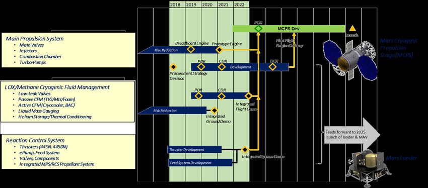
Nomenclature
V = Propulsive Delta Velocity (m/s)
ARM Asteroid Redirect Mission
AR&D Approach, Rendezvous & Docking
CFM Cryogenic Fluid Management
EMC Evolvable Mars Campaign
EOI Earth Orbit Insertion
GN&C Guidance, Navigation & Control
LDHEO Lunar Distant High Earth Orbit
LDRO Lunar Distant Retrograde Orbit
LEO Low Earth Orbit
MAV Mars Ascent Vehicle
MCPS Methane Cryogenic Propulsion Stage
MDV Mars Descent Vehicle
MOI Mars Orbit Insertion
MPCV Multi-Purpose Crew Vehicle
MPS Main Propulsion System
RCS Reaction Control System
SEP Solar Electric Propulsion
SLS Space Launch System
TEI Trans Earth Injection
TLI Trans Lunar Injection
TMI Trans Mars Injection
TRL Technology Readiness Level
I. Introduction
N ASA is currently developing a new long-term strategy to expand human exploration of space beyond the
confines of low Earth orbit and into the solar system. This Pioneering Space strategy focuses on evolving
space exploration capabilities from our current Earth Reliant state, through a cis-lunar Proving Ground of
technology demonstrations and incrementally more challenging human space flights, to an Earth Independent state
where crews of astronauts live and work on the surface of Mars. To provide the context for identifying and
prioritizing technology investments along that path to Mars, the Evolvable Mars Campaign (EMC) is supporting an
ongoing series of architectural trade analyses. The EMC is integrating teams from across NASA to investigate
common capability needs across three broad areas; transportation, habitation, and destination systems. At its core,
the EMC is not a study to define the next Mars design reference mission, but rather a series of ongoing studies
designed to understand the potential future paths for human Mars exploration within the context of the Pioneering
Space strategy, placing emphasis on affordability, sustainability, and reusability.
The Pioneering Space strategy is built on a set of key principles for a sustainable and affordable space program
that help ensure NASA’s investments efficiently and effectively achieve the nation’s space exploration goals. These
principles include:
• Implementable in the near-term with the buying power of current budgets and in the longer
term with budgets commensurate with economic growth;
• Exploration enables science and science enables exploration, leveraging robotic expertise for
human exploration of the solar system;
• Application of high Technology Readiness Level (TRL) technologies for near term missions,
while focusing sustained investments on technologies and capabilities to address challenges of
future missions;
• Near-term mission opportunities with a defined cadence of compelling and integrated human
and robotic missions providing for an incremental buildup of capabilities for more complex
missions over time;
• Opportunities for U.S. commercial business to further enhance the experience and business
base;
• Multi-use, evolvable space infrastructure, minimizing unique major developments, with each
mission leaving something behind to support subsequent missions; and
2
American Institute of Aeronautics and Astronautics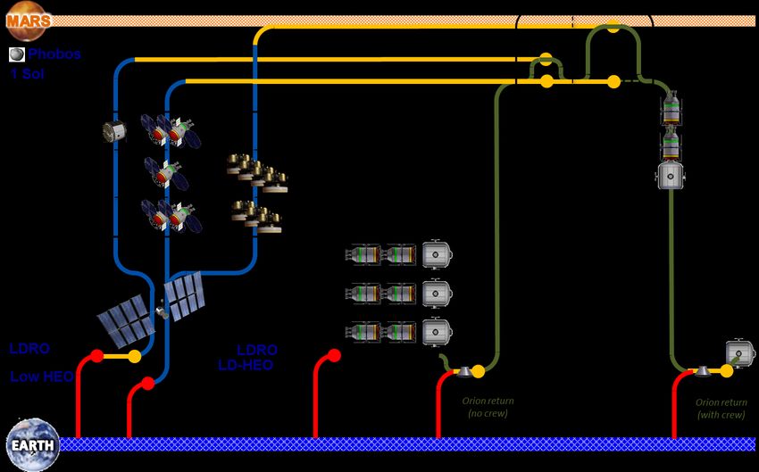
•    Substantial new international and commercial partnerships, leveraging the current
           International Space Station partnership while building new cooperative ventures.

    The EMC team has been working to identify and evaluate a suite of potential mission architectures, integrating
transportation, habitation, and destination systems in a mission construct that supports successful human Mars
exploration within the guidelines of the Pioneering Space strategy. Several papers are being published at the AIAA
Space 2016 conference by these various teams to provide an overall picture of the breadth and depth of the ongoing
EMC work.
    A key component of the Mars exploration plan is liquid oxygen – liquid methane propulsion. This capability is
leveraged not only for the Mars Descent Vehicle (MDV) and Mars Ascent Vehicle (MAV), but also for in-space
transportation of crew to and from the Martian system using a mission element known as the Methane Cryogenic
Propulsion Stage (MCPS). The common use of this methane propulsion system across many elements of the
architecture offers a potential reduction in development and production costs by limiting the number of engine
development programs, and increasing the number of flight units required for the execution of the overall campaign.
Reliability of the MDV and MAV is also increased by accumulating operational time on the engine design through
the use of multiple MCPS in the initial Mars orbital mission of the campaign. Finally, the use of methane
propulsion for Mars dovetails with past, current, and planned technology investments, expanding on previous work,
leveraging current work within and outside of NASA, and laying the groundwork for future, improved in-space
transportation technologies.
    This paper provides an overview of the recent work completed in the design and planning of the MCPS and the
methane propulsion system at its core. The EMC split Solar Electric Propulsion (SEP)-Chemical campaign and key
mission attributes are discussed to provide context for the requirements used to design the MCPS. The most recent
round of bottoms-up MCPS design work is outlined including performance sensitivity analyses. Finally, an
overview of the potential development path for key technologies of the integrated methane propulsion system is
provided, including technology needs and projected timelines for development.

                        II. A Brief Overview of the Evolvable Mars Campaign
    The EMC does not seek to prescribe a particular path for exploring Mars, but rather seeks to better clarify and
understand the various paths available to help guide the next 20 years of technology developments as NASA moves
closer to its long-term goal of sending humans to Mars. A small set of ground rules and constraints guide the various
trade analyses and design studies being performed. These ground rules include:

      •    Humans to the Mars System by mid-2030’s
      •    Propulsion technology will utilize solar-electric systems extensible from the Asteroid Redirect
           Vehicle spacecraft bus
      •    Earth-to-Orbit SLS Block 2 launch vehicle and Orion spacecraft will be available
      •    Vehicle checkout and assembly (aggregation) in a lunar distant retrograde orbit (LDRO) to
           leverage infrastructure established during Proving Ground phase
      •    Crew of four to Mars system
      •    Crewed vehicle reusability for sustainability and potential cost advantages where reasonable

    Several different general transportation architecture approaches are being investigated as part of the ongoing
EMC study. These options leverage the investments in high-power SEP being made to support the Asteroid
Redirect Mission. One such transportation architecture approach currently being investigated is referred to as the
SEP-Chemical approach. This family of architecture options splits the functions of crew and cargo delivery into two
distinct transportation approaches. High-efficiency SEP is used to deliver all cargo to Mars, including Phobos
exploration elements, Mars landers, and crew Earth return stages. These cargo delivery flights, while longer in
duration, can be achieved in single launches using the Space Launch System (SLS) Block 2 vehicle. Flight time
reductions can be realized by increasing the number of SLS launches used to emplace these elements, or by
increasing the power of the SEP vehicle.
    While slower trajectories may be acceptable for cargo elements, the crew flight duration must be significantly
shorter to minimize the impacts of zero gravity and prolonged radiation exposure. The SEP-Chemical architectures
employ the MCPS for these crew flights, using more traditional high-thrust, conjunction-class trajectories. Previous
Mars exploration studies have not considered methane propulsion as a means for interplanetary flight because the
specific impulse of such a systems is approximately 100 seconds lower than that of the liquid oxygen – liquid

                                                        3
                                American Institute of Aeronautics and Astronautics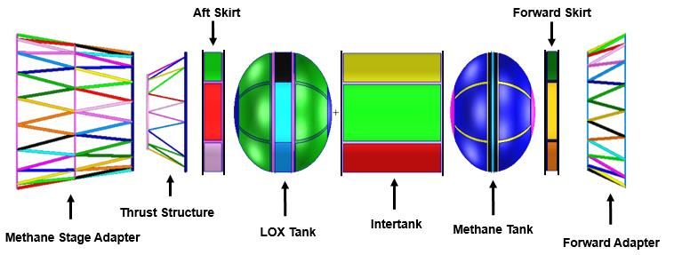
hydrogen systems considered in many of the past Mars architecture studies, including NASA’s Design Reference
Mission 5.01. However, some unique aspects of the SEP-Chemical architecture enable the use of these lower-
performing methane stages which allows mission designers to side-step some of the technical challenges associated
with long duration liquid hydrogen storage.

                                   III. The SEP-Chemical Architecture
    While there are several architecture options currently under investigation in the EMC, the MCPS is primarily
being considered for use in the SEP-Chemical architecture. The SEP-Chemical architecture uses a traditional
chemical propulsion approach to crew delivery and places technology development focus on long-duration cryo
fluid management. Cargo, including Earth return propulsion, landers, and exploration equipment, is pre-deployed
using high-efficiency SEP stages. The following section provides an overview of the current baseline SEP-
Chemical transportation architecture and provides insight into the functional requirements of the MCPS.

A. Mission Sequence of the Campaign
    The baseline EMC SEP-Chemical campaign consists of three, progressively more challenging human Mars
exploration missions. In 2033, a crew of 4 will depart on the first human mission to Mars and will explore the
Martian moon Phobos. This mission will be followed in 2039 by the first human landing on Mars. The crew of 4
will spend the bulk of their stay living, working, and exploring on the surface of Mars. In 2043, a new crew will
return to the same landing site to continue Mars surface exploration, building on the infrastructure remaining after
the first surface mission. After these three initial missions a steady cadence of surface missions would continue but
the steady-state phase of Mars surface exploration is beyond the scope of the emplacement phase being studied by
the EMC teams.
    For each of the three missions, several elements are pre-deployed to Mars using a high-power SEP vehicle. The
Phobos mission requires a Phobos habitat for the crew to work out of during their stay in the Martian system. Each
surface mission requires multiple Mars Descent Vehicles to land surface equipment and crew on Mars. All three
missions pre-deploy the Earth return propulsion systems to Mars where the crew will rendezvous with them upon
arrival in the Martian system. Pre-deployment of the Earth return stages greatly reduces the stack size for crew
flights to Mars. However, due to the relatively low power levels of the current SEP vehicle design, these stages are
launched into space up to 7 years prior to being used, setting a requirement for these stages to operate after very long
periods of dormancy.
    Each SEP pre-deployment flight is launched by a single SLS Block 2 launch vehicle to an elliptical Earth orbit
with an apogee determined by the total wet stack mass of the SEP vehicle and its payload. The SEP vehicle then
performs a slow spiral trajectory to climb towards Earth escape. All crew flight stacks are launched piece-by-piece
to the LDRO where they are assembled. The completed crew flight stack is then transferred to a Lunar Distant High
Earth Orbit (LDHEO) where the crew meets the stack, transfers into the transit habitat, and departs for Mars. An
overview of the flights that make up the current baseline 3-mission campaign is provided in Figure 1. A more
complete overview of the SEP-Chemical campaign can be found in Reference 2.

B. Derived Requirements for Flight Regimes of the Methane Cryogenic Propulsion Stage
    The unique combination of long-duration SEP flights and LDRO aggregation brings with it a diverse set of
operational requirements for the MCPS. In order to set the stage for the design update performed earlier this year, a
complete review of the concept of operations was performed identifying the key driving requirements for the MCPS.
Among the goals of this effort was the identification of operating environments and operational lifetime
requirements. General functional requirements identified include the ability to operate as a free-flying, autonomous
spacecraft and the ability to dock with various mission elements including other MCPS and habitation modules. The
ability to store cryogenic liquid propellants for long durations at very low loss rates led to a requirement for active
cryogenic fluid management (CFM) and the ability to produce the associated power required to run those systems.
Analysis of functional requirements focused on the two different flight regimes experienced by the MCPS in the
architecture; that of a pre-deployed mission element and that of an active crew flight element.

                                                         4
                                 American Institute of Aeronautics and Astronautics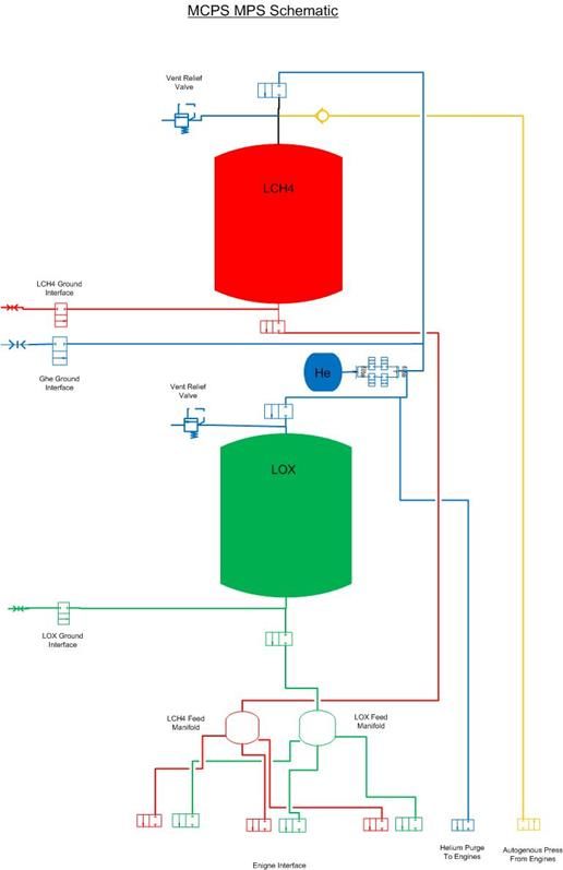
Figure 1. Overview of the Baseline SEP-Chemical Architecture for the Evolvable Mars Campaign. The SEP-
Chemical architecture consists of a series of pre-deployment flights using a 150 kW SEP vehicle followed by crew
flights to Mars using traditional high-thrust conjunction-class trajectories with methane propulsion systems. Pre-
deployed elements are launched with their SEP vehicles while crew elements are stacked in LDRO prior to Earth
departure.
1. Pre-Deployed Mission
The pre-deployment of MCPS involves five phases; low-thrust Earth escape, low-thrust interplanetary flight,
Mars Orbit Insertion (MOI), loiter in Mars orbit, and rendezvous and dock with crew elements. Many of these
phases are driven by the mass of the MCPS being delivered, a value that can range from 20t to 50t depending on the
flight opportunity and burn allocation. As the mass of the MCPS increases, the low-thrust portions of the pre-
deployment will be extended and the propellant required for MOI will also increase. During the Earth escape phase
of pre-deployment, the MCPS and SEP vehicle are launched by an SLS Block 2 launch vehicle to an elliptical orbit
with an apogee that is driven by the combined weight of the Mars elements. With a perigee fixed at 200 km altitude,
the apogee of the initial parking orbit can vary from 6,000 km to 105,000 km altitude for the range of MCPS sizes
required for the architecture. The slow spiral trajectory is longer for lower initial apogees and spiral times can range
from 4 months to 3 years. Two typical altitude profiles are provided in Figure 2. Spiral profiles provide insight into
the operational environments experienced by the MCPS, specifically the thermal environments that contribute to the
design of the CFM system required to store the cryogenic propellants.
Once the SEP vehicle stack has escaped from Earth, the interplanetary flight phase begins. While steadily
increasing the distance from the Sun, the low-thrust interplanetary trajectories still take from 435 – 865 days to
complete. The end destination for the pre-deployed MCPS is a 10 Sol Mars parking orbit. It is here that these pre-
deployed stages will meet with the crew transit habitat to support Mars departure and Earth arrival for the crew
return trip. The current SEP vehicle design does not provide adequate power to support a propulsive capture using
the SEP thrusters at Mars due to the size of the solar arrays and the distance from the Sun. This necessitates a
propulsive capture using the MCPS. In order to minimize the impact to the size of the MCPS, the V for the MOI
maneuver is minimized using a combination of two techniques. First, the 10 Sol parking orbit at Mars provides a
5
American Institute of Aeronautics and Astronautics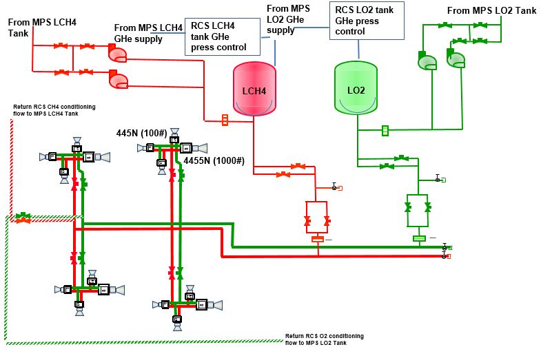
Figure 2. Earth Escape Spiral Profiles. Several of the MCPS in the SEP-Chemical architecture are pre-deployed
to Mars using SEP vehicles. These pre-deployment flights begin with an Earth escape spiral maneuver during
which the Earth parking orbit is slowly raised. These two graphs show two typical perigee and apogee altitude
time profiles. The graph on the right represents a larger MCPS stack with a lower initial apogee and a longer
spiral while the graph on the left represents a lighter MCPS stack with a higher initial apogee a shorter spiral.
very high periapse velocity to close the velocity gap between the incoming hyperbolic trajectory and the parking
orbit. This gap is further reduced by using the high-efficiency SEP propulsion during interplanetary flight to reduce
the Mars arrival velocity to 0.5 km/s. The total MOI phase V budget includes the initial orbit insertion burn and
additional accomodations for orbit maintenance and alignment.
After completing the MOI phase of the pre-deployment, each MCPS will spend time loitering in the 10 Sol orbit
while awaiting the arrival of the crew transit habitat. This loiter duration is highly dependent on the launch phasing
of elements, but can be as long as 2 years. When the crew stack does arrive at Mars, the pre-deployed stages will
perform rendezvous and dock maneuvers to attach to the crew transit habitat. Once stage capture has been
completed, the remainder of the mission will be carried out. The pre-deployed stages will complete the transfer to a
1 Sol orbit and perform orbit maintenance while the crew is on the surface of Mars. Upon completion of the surface
mission, the pre-deployed stages will provide the Trans Earth Injection (TEI) and Earth Orbit Insertion (EOI) burns
for the crew transit habitat. Mars stay times range from 350 to 530 days for the opportunities being considered and
Earth return flight times range from 200 to 350 days. Looking at the duration requirement for each individual stage
for the specific opportunities investigated, it was determined that the maximum in-space duration for an MCPS will
be the nearly 3000 day lifetime of the pre-deployed TEI/EOI stage used in the 2039 crew mission.
2. Active Crew Flight
The second flight regime, the active crew flight regime, yields a different set of functional requirements. The
active crew flight regime encompasses time spent aggregating with and actively flying the crew transit habitat to and
from Mars. This flight regime consists of 4 phases; aggregation, planetary departure, active flight, and planetary
arrival. The active crew flight elements perform all propulsive maneuvers connected with the transfer of crew to
and from Mars. The MCPS for Trans Mars Injection (TMI) and MOI are connected to the transit habitat at Earth,
while the TEI and EOI stages are pre-deployed to Mars and connected with the transit habitat in Mars orbit as
described above. Aggregation at Earth takes place in the LDRO around the Moon. The stages must be capable of
performing automated rendezvous and docking with other elements in LDRO, and will be required to loiter in
LDRO until the crew stack is completed. Once complete, the crew stack is moved from LDRO to a LDHEO
through a series of small propulsive and lunar gravity assist maneuvers. Once in LDHEO, the crew will meet the
transit habitat in an Orion Multi-Purpose Crew Vehicle (MCPV), transfer into the habitat, undock Orion and target
an Earth departure burn at perigee of the LDHEO. The TMI MCPS performs the TMI maneuver and is jettisoned.
The MOI MCPS performs any trajectory corrections required during the active flight phase to Mars, and then
performs the MOI maneuver to capture into a 10 Sol orbit upon arrival at Mars. The MOI MCPS then guides the
habitat through rendezvous and docking with the pre-deployed stages and is jettisoned once the docking is
completed.
Operations in the 10 Sol orbit very closely resemble the rendezvous and dock operations of an aggregation phase
and mark the beginning of the active crew flight regime for the pre-deployed stages. Most crew flight opportunities
will pre-deploy two MCPS, one for Mars departure and one for Earth arrival. However, in the 2039 flight
opportunity, these two functions are combined into one MCPS. Whether one or two stages, the pre-deployed
6
American Institute of Aeronautics and Astronauticselements must perform rendezvous and dock maneuvers with the transit habitat in the 10 sol orbit and then transfer
the stack to the 1 Sol Mars parking orbit. While in that orbit, the stages perform station keeping and orbital
realignment while the crew explores the surface of Mars. When the crew is ready to return to Earth, the MCPS will
perform a sequence of maneuvers to raise the Mars parking orbit and align for TEI. The Mars departure and Earth
arrival burns are performed in much the same way as the TMI and MOI burns on the outbound leg of the crew
mission. Upon Earth arrival, the crew transfers into an Orion MPCV to return to Earth’s surface, and the EOI
MCPS returns the transit habitat to LDRO for refurbishment and reuse on the next crew flight to Mars.
C. Derived Requirements of the Methane Cryogenic Propulsion Stage
A review of the two flight regimes identifies several functional requirements for the MCPS. The requirement for
automated rendezvous and docking requires the MCPS to be capable of operating as a free-flying spacecraft. A
suite of sensors, including a full complement of guidance, navigation, and control systems, and docking hardware
must be provided and the stage must be capable of independently determining its state. The periods of free flight, in
transit to the LDRO as well as loitering in both LDRO and Mars orbit, require some limited communications
capability to transmit housekeeping data. Independent flight also implies that the stage must be capable of providing
its own power. Additionally, the requirements for active CFM drive the required power levels beyond the capability
of batteries, implying the need to include solar arrays in any MCPS design.
Flight environments and durations are key metrics for determining what is required of the CFM systems.
Thermal environments for this mission are most extreme in orbit around Earth, the moon, and Mars. As the SEP
vehicle slowly spirals up through Earth’s gravity field, the albedo effect of the Earth is slowly reduced. The LDRO
orbits the Moon at approximately 80,000 km altitude, somewhat diminishing the Moon albedo effect. The distance
of Mars from the Sun reduces the overall thermal environment challenges of long duration Martian orbit. However,
a detailed thermal analysis was required, accounting for environment and duration as well as orientation to the Sun,
to fully understand which phases are the thermal drivers for CFM. This analysis is detailed in the following section.
Several propulsion requirements are also derived from the functional view of the concept of operations. Many
applications of the MCPS require at least one main engine restart during the course of the mission. In the case of the
2039 Earth return stage, the main engines must be started twice with nearly 300 days of interplanetary flight
between those two starts, necessitating the inclusion of a robust main propulsion system (MPS) purge system to
ensure survival of the dormancy period. There are also several instances of burns which are relatively low V but
require steady state operation of a propulsion system. These maneuvers include the MOI burns for the pre-deployed
stages as well as powered lunar gravity assist maneuvers during the transit to LDRO both during aggregation and
during repositioning of the transit habitat after Earth return. These burns, if completed with the MPS, would be very
short in duration, many less than 1 minute. In order to minimize the impact to the main propulsion system and
reduce the number of main engine starts, it was decided that the requirement to perform these burns would be
absorbed by the reaction control system (RCS), leading to a unique RCS design. Additionally, the duration of the
MCPS operations (up to 3000 days) led to the requirement for very low leakage valves to minimize propellant loss.
IV. Design of the Methane Cryo Propulsion Stage
The general concept of a methane-based in-space transportation stage has been considered for human Mars
missions for several years now. While chemical in-space propulsion for larger missions has often led to the
assumption of the higher performing hydrogen-based systems, there are several technical challenges associated with
the long term storage of hydrogen in space. By comparison, liquid-oxygen / liquid-hydrogen stage concepts typically
assume specific impulse values around 460 seconds, while a typical liquid-oxygen / liquid-methane engine may
provide somewhere between 340 and 375 seconds of specific impulse, depending on the selection of an engine
cycle. However, the storage temperatures of methane are considerably higher than hydrogen and much closer to
those temperatures required for oxygen. The storage density of methane also provides additional design benefits.
The challenge, then, is to find a way to overcome the reduction in specific impulse in order to take advantage of the
technology and design benefits of methane.
When the Evolvable Mars Campaign study began, investigators looked for operational opportunities to reduce
the energy requirements of in-space transportation systems to find ways around requiring the extreme performance
of hydrogen-based stages. Previous Mars architectures have limited aggregation to Low Earth Orbit (LEO) to
maximize the mass lofted to orbit, but this greatly increases the Earth departure energy requirement. By taking
advantage of the SLS lift capacity to Trans Lunar Injection (TLI), the EMC mission profiles aggregate in cis-Lunar
space and depart from LDHEO. Departure from LDHEO greatly reduces the energy requirement for the TMI burn,
where the crew transit stack is its heaviest. Pre-deployment of the Earth return stages also reduces the crew transit
7
American Institute of Aeronautics and Astronauticsstack mass at Earth departure which also reduces the amount of propellant required for both Earth departure and
Mars arrival. The SEP vehicle efficiently performs this pre-deployment. While this does introduce a new risk to the
mission concept of operations, this pre-deployment in concert with departure from high Earth orbits, enables the use
of the methane propulsion systems and avails program managers of the technical and design benefits of the higher
temperature, higher density propellant choice.
While the EMC study teams had been leveraging older concepts for methane transportation stages in the early
architecture work, this past year the study teams decided a refresh of the design was in order. In addition to
reaffirming some of the design selections previously baselined, this design effort served to add fidelity in two
specific technical disciplines; the integrated methane propulsion system and the CFM system. Structural mass was
updated based on the latest set of structural requirements and the power system was updated to meet the latest power
generation requirements. This bottoms-up design effort not only provided higher fidelity mass estimates of the stage
for use in transportation architecture analyses, but also served as the backbone for the technology development plan
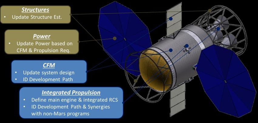
discussed in Section VI of this paper. A concept drawing of the MCPS identifying the main areas of focus for this
design study is provided in Figure 3.
Figure 3. The Methane Cryogenic Propulsion Stage. The MCPS design update primarily focused on increasing
the fidelity of the integrated propulsion and CFM sub-system designs as well as updating the power and structures
designs to absorb any additional requirements resulting from the refinement.
A. Propulsion
The integrated propulsion system consists of three 22,500 lbf main engines and four sets of reaction control
thrusters. The main engines at the heart of this system are the same main engines being assumed by the EMC Mars
Lander team for both the MAV and the MDV. An independent assessment of engine requirements was conducted
reviewing mission requirements for all three of these Mars elements, and it was determined that the packaging and
performance requirements of the Mars lander systems will drive the design of the main engine itself. In order to
maintain commonality across the various elements and build a Mars program that requires only one main engine
development program, it was assumed that the same engine would be used for the MCPS. The mass of the engine,
is comparable to the mass of an RL-10 engine. Helium purge gasses are used to ensure that feed lines are clear of
any residual propellants after main engine firings and prior to long duration periods of dormancy.
The stage configuration consists of two in-line propellant tanks. Constructed from aluminum, these tanks are
held at 50 psia tank pressure and have a diameter of 4 meters. Tank pressurization is provided by an ambient
gaseous helium system with a tank pressure of 4500 psia. One technology investment area identified for the
integrated propulsion system specifically related to the feed system is low leakage valves. These valves must be
capable of cycling through multiple burns, sometimes with several hundred days between them, while maintaining
leak rates less than 0.0053 kg/day. This leak rate represents a 100x improvement over current state of the art valves,
however, work is currently underway investigating various methods for improving leak rate. This is discussed
further in the technology development section below. A schematic of the MPS and tanks is provided in Figure 4.
8
American Institute of Aeronautics and AstronauticsThere are two unique aspects to the
design of the RCS system of the MCPS.
Like most traditional reaction control
systems, the MCPS RCS system consists of
four thruster pods each containing four
thrusters. However, in order to support the
series of smaller steady-state burns required
for LDRO operations and MOI of the pre-
deployed stages, each thruster pod uses a
1000 lbf thruster pointed in the aft axial
direction. The remaining three thrusters in
each pod are 100 lbf thrusters. The
combined axial 4000 lbf of thrust is capable
of performing all smaller translational burns
for which the MPS would be overkill. With
the RCS system absorbing this extra work
load for each stage, the RCS propellant
loads can quickly grow to several thousand
kilograms. In a traditional pressure-fed
RCS system, this would translate to very
large propellant tanks and significant
helium loads. To reduce the impact of this
additional work and increase the overall
stage operational flexibility, the RCS
system for the MCPS uses liquid-oxygen /
liquid-methane thrusters that are fed from
the main propellant tanks. A notional
schematic of this system is provided in
Figure 5.
The integrated RCS system uses
accumulator tanks which are sized to hold
the propellant required for a single
translational maneuver. These accumulator
tanks are fed from the main propellant tanks
Figure 4. Methane Main Propulsion Systems. The methane MPS by a set of electric pumps which draw in the
consists of two in-line cylindrical propellant tanks and a small appropriate propellant load and provide tank
helium pressurization system to feed three 22,500 lbf pump-fed pressurization for operations. This
oxygen-methane engines pressurization is supplemented by a gaseous
helium system, however, the helium load is
greatly reduced due to the smaller accumulator tanks and the electric pumps employed to feed the tanks. From the
accumulator tanks to the thruster, the RCS system operates as a traditional regulated pressure-fed system. Propellant
flow to the electric pumps is tapped off the flow system used by the CFM circulators which minimizes the number
of penetrations into the main propellant tanks.
There are several operational benefits to using this type of RCS system. First, the use of methane-based RCS
thruster increases the specific impulse from 325 seconds to 340 seconds. The use of accumulator tanks rather than
packaging all of the required RCS propellant into a separate system from the main propellant tanks not only reduces
the size of the relatively high pressure RCS propellant tanks, but also provides additional propellant inventory
flexibility. This flexibility adds an additional set of contingency operational modes where translational V can be
provided by two separate systems. The central storage of all propellants in the main tanks also allows a single set of
CFM systems to maintain liquid propellant storage conditions reducing the complexity of the CFM system while
maintaining the higher performing methane-based RCS.
9
American Institute of Aeronautics and AstronauticsFigure 5. Integrated Methane RCS. The integrated RCS system for the MCPS consists of electric-pump-fed
accumulator tanks tied to pods of RCS thrusters. Each pod consists of three 100 lbf thrusters and one 1000 lbf axial
thruster for translational maneuvering.
B. Thermal Control
The primary focus of the thermal control system design analysis was the CFM system. To fully understand the
requirements of the CFM system, specifically the passive elements and the cryocooler, a broad evaluation of the
various thermal environments experienced by
the MCPS was completed. Reviewing the Table 1. Thermal Loads. The MPS storage tank total heat load
concept of operations in both flight regimes was calculated using Thermal Desktop for a variety of
(pre-deployed and active flight), environments environments and vehicle orientations.
include long duration slow-climbing elliptical MPS Storage Tanks
orbits around Earth, and long duration Vehicle Total Heat Load
MCPS Thermal Environments Orientation (W)
assembly in LDRO, interplanetary space, and
long duration loiter in Martian orbit. Thermal Delivery to aggregation
Desktop was used to evaluate the heat load in SEP Early Spiral, Arg. Periapsis 180° +XVV 38
these environments with different spacecraft SEP Early Spiral, Arg. Periapsis 270° +XVV 43
orientations. Table 1 shows the heat load SEP 30000 km Circular +XVV 51
results from the environmental analysis. All Chemical Lunar Transit +XSI 80
heat loads include a 25% margin. Two main Chemical Lunar Transit Broadside +ZSI 39
results should be noted from this analysis.
First, it should be noted that orientation is a Aggregation and beyond
powerful means to reduce heat load into the Low HEO +XSI 76
propellant tanks. A comparison of the heat LDRO +XSI 79
LDRO Engines-to-Sun -XSI 28
loads in LDRO shows that by pointing the
LDRO Broadside +ZSI 40
engines towards the sun, the heat load can be LDHEO +XSI 80
reduced from a nominal 79 W to 28 W. The Mars Transit +XSI 34
second finding in this analysis is that none of 1Sol +XSI 28
the scenarios investigated result in a heat load
into the MPS tanks in excess of 100 W.
The design of the thermal control system is divided into two main functions. The first is the thermal
conditioning of various sub-systems including avionics and propulsion. This system consists of a state-of-the-art
cold plate and evaporator system tied into deployable radiators using an ammonia coolant loop. The second main
function is the removal of heat energy from the main propellant tanks to maintain cryogenic storage conditions. The
cooling approach for the tanks consists of a single 90K reverse turbo-Brayton cryocooler based on work completed
by Zagarola, et al.3 A tube-on-tank-wall broad area cooling network is used to cycle cooling fluids over the tanks
and into the cryocooler. From there, the cryocooler ties directly into the deployable radiators using an ammonia
10
American Institute of Aeronautics and Astronauticscooling heat exchange loop similar to the coldplate system. The active cryocooling systems are supplemented by
multilayer tank insulation. The reverse turbo-Brayton cryocooler has a total lift of 100 W which is more than
sufficient to handle even the most extreme heat loads anticipated. The cryocooler and supporting subsystems are
estimated to weigh 89 kg and require 1.1 kW of input power, which includes a 15% power margin.4 As with the
engine system, the cryocooler technology is assumed to be the same for all elements in the Mars campaign that
require methane propulsion, including the MAV and MDV used for Mars surface access.
C. Power
The power sub-system on the MCPS is Table 2. Power Profile. The solar power system power
designed to drive all electrical systems at production requirements were evaluated for various mission
Mars according to a mission-phased power phases to determine the peak power production required for the
profile. Power requirements were gathered MCPS mission.
for the various avionics and propulsion
components, as well as the thermal control
system, most notably the CFM system.
Additionally, the power requirements for the
electric pumps that drive the RCS
accumulator tank filling were accounted.
The power profile assumption by phase is
provided in Table 2. Batteries are included in
the power system design to accommodate
power requirements during various mission
phases. Because orientation during docking may preclude arrays from seeing sunlight, battery power must be
available during certain times in the docking and assembly process. Main propulsion will not be used during these
times, so 2 hours of avionics and CFM power have been ground-ruled. Battery power is also used to supplement
solar array power production for peak loading from the avionics and propulsion system during propulsive
maneuvers. Battery power is sized to provide full power to essential systems for 2 hours and supplemental power
for peak power draw applications for 1 hour. Due to the large number of battery cycles assumed during the course
of the MCPS mission, 40% is the max depth of discharge for the batteries. Depth of discharge can be increased to as
much as 80% for end of life operations where the stage will not be required to function after that discharge.
The design of the power system assumes the use of UltraFlex solar arrays. These arrays are sized to provide the
maximum power load, 4.4 kW, at end of life at Mars. Accounting for array cell degradation and Martian solar
distance, this requirement results in two UltraFlex arrays of 23.5 m2 each assuming 70% cell coverage. Each array
wing has a diameter of 5.6 m, a mass of 46.8 kg, and a maximum acceleration limit of 2.5 g.
D. Structures
A structures analysis was completed to provide updates to all of the structural members of the MCPS. The
MCPS consists of two propellant tanks, an intertank segment between them, and forward and aft skirts at either end
of the tank assembly which connect to thrust structure and adapters. Figure 6 shows the FEA model of all structural
elements in the MCPS design. All panel structural elements, including tanks, are made of 2219-T87 aluminum,
while all truss structures are made of composite materials. A finite element model was made of the structural
elements of the MCPS and the structures were optimized using a combination of MSC Patran and Hypersizer.
Assessments included strength and stability checks for launch, ascent, and in-space operations. The driving
operational case for loads analysis was the launch of an MCPS with a SEP vehicle, the launch configuration of all
pre-deployed MCPS. The SEP vehicle was modeled as a block mass above the MCPS. Axial loads of 3.5g and
lateral loads of 1.5g were assumed. The focus of the structures analysis in this effort was the refinement of the
primary structures mass incorporating changes to the design resulting from refined analysis of other sub-systems. As
such, the secondary structures were not explicitly evaluated and a 20% mass increase was assumed to account for all
secondary structures in the MCPS. A multiplyer was added to the mass estimate of all truss structures to account for
joints and fittings.
11
American Institute of Aeronautics and AstronauticsFigure 6. Structures Modeling. The finite element model of all structural components of the MCPS was
evaluated using a combination of MSC Patran and Hypersizer.
E. Avionics
The avionics system design for the MCPS was driven primarily by the requirement for free-flying and automated
rendezvous and docking operations. Each stage in the architecture must provide its own guidance, navigation, and
control (GN&C) system and be capable of determining its own state at all phases of the mission. The stages must
also be capable of transmitting housekeeping data to Earth to support system health monitoring. Stages also provide
command and data links to all other stages in the stack. The avionics architecture for the stage is designed to be
single-fault tolerant for critical systems needed for mission success and to maintain long term GN&C fault tolerance.
The attitude and control system includes sun sensors, star trackers, and inertial measurement units. The command
and data system include independent computers (using a triple-voting scheme), data acquisition units and solid state
data recorders. The systems designed to support rendezvous and docking includes long range and short range
approach, rendezvous, & docking (AR&D) systems. A suite of system controllers support general vehicle systems
such as CFM controllers, propulsion controllers (MPS, RCS, Thrust Vector Control), and jettison controllers. Each
stage is also equipped with instrumentation, which includes pressure sensors, temperature sensors, strain sensors,
and video monitoring cameras (for health and status). Finally, the avionics suite on each stage includes a
communications system which consists of a Ka-band high gain system (for a high data rate link between Earth and
Mars), an S-band medium gain system (for ground link in low Earth and Mars orbits), and a low gain system (for in-
space inter-stage communications and AR&D).
F. New Mass Estimate and Comparison
One main result of the design refresh effort was to produce a new MCPS mass estimate for use in architecture
analysis trades going forward. The mass estimates for each subsystem described above were assembled to complete
an update to the MCPS dry mass estimate. These estimates were based on a combination of analysis and off-the-
shelf component selection. The AIAA standard for mass growth allowance was applied to each item in the mass
breakdown commensurate with the technology readiness level of the component and the level of fidelity of the
analysis that produced the mass estimate.5 This resulted in a composite contingency mass of 20.94%. Table 3
provides a complete summary of the MCPS point design mass estimate.
In addition to the dry mass estimate, the MCPS propellant inventory was also evaluated and updated. The
MCPS must carry not only the propellant required to complete all main propulsion and RCS burns but also the
propellant to cover various loss sources throughout the mission. Start up and shut down propellant loads were
estimated for each main engine operation based on the liquid oxygen transient losses of current state-of-the-art boost
engines. Propellant required to chill the feed lines prior to engine start was also estimated based on currently fielded
engines. While the CFM system is designed to maintain cryogenic propellant storage temperatures throughout the
mission, it is acknowledged that a small amount of propellant will be lost during initial stage ascent on the SLS,
while the CFM system is inoperable. Another small amount of propellant will be lost to ullage gases as the tanks
move towards steady-state operations. Propellant leakage was also accounted based on the 100x improvement over
current state of the art cryogenic valves as discussed in the propulsion subsection above. A residual percentage of
1% was assumed to account for trapped propellants. The design team assumed that the RCS system would be used
to settle tanks when a propellant load measurement was required in order to baseline settled mass gauging
technologies rather than the still experimental zero-g mass gauging technologies currently under investigation. This
12
American Institute of Aeronautics and Astronauticsreduced the assumed mass gauging error to 0.6%, a value in line with current in-space stages. An additional 1.4%
reserve propellant load brought the overall unusable propellant estimate to 3% plus the measureable or estimated
values discussed above. Mission and operational contingencies were added through finite burn analyses and V
margins which lead to an initial calculated burned propellant value that accounts for mission-level variability related
to trajectory and timing issues. Therefore, these contingencies do not manifest as individual margins within the
propellant inventory. The full propellant inventory for the MCPS design point is included in the Table 3 mass
estimate summary. Table 4 provides a summary of the basis of estimate for the unusable propellant inventory.
Table 3. MCPS Mass Estimate Summary. The mass estimate of the MCPS is broken down by sub-system and
includes a contingency mass growth consistent with the AIAA standard. The dry mass is provided as well as the
unusable propellant inventory.
MEL - MCPS Basic Mass (kg) Contingency (%) Contingency (kg) Predicted Mass (kg)
Mass Breakdown Structure
1.0 Structures 2582.28 20.72% 535.03 3117.31
2.0 Propulsion 2313.57 22.61% 522.99 2836.55
3.0 Power 565.40 15.00% 84.81 650.21
4.0 Avionics 748.25 17.62% 131.85 880.10
5.0 Thermal 634.06 24.94% 158.17 792.23
Dry Mass 6843.56 20.94% 1432.84 8276.40
6.0 Non-Prop Fluids 2238.35 2238.35
6.1 MPS Engine Start/Stop Propellant 636.00 636.00
6.1.1 Fuel 141.33 141.33
6.1.2 Oxidizer 494.67 494.67
6.2 MPS Vapor Loss 150.00 150.00
6.2.1 Ullage Vapor 100.00 100.00
6.2.2 Ascent Heating 50.00 50.00
6.3 Propellant Reserves & Residuals 1044.00 1044.00
6.3.1 Fuel 232.00 232.00
6.3.2 Oxidizer 812.00 812.00
6.4 Propellant Leakage 272.00 272.00
6.4.1 Fuel 136.00 136.00
6.4.2 Oxidizer 136.00 136.00
6.5 Fuel Bias 77.35 77.35
6.5.1 Fuel 77.35 77.35
6.6 Propellant Pressurant 59.00 59.00
6.5.1 MPS GHe 59.00 59.00
Inert Mass 2238.35 2238.35
Total Less Propellant 9081.91 10514.75
7.0 Usable Propellant 34805.80 34805.80
Total Stage Gross Mass 43887.71 45320.55
Table 4. Unusable Propellant Inventory Basis of Estimate. Various sources of unusable propellant are
accounted for in the estimate of the MCPS inert mass. These unusable propellant loads are partially based on
historical data and partially based on industry standard practices.
The point estimate for the MCPS provides several insights into the design constraints and requirements for
technology development which are discussed later in this paper. However, as part of an integrated mission
architecture analysis effort, the MCPS point design must inform a flexible method of estimating the mass of the
MCPS given a wide range of potential mission constraints. Architecture analyses completed for the EMC study
account for variations in payload masses as the design of various payload elements, including the crew transit
13
American Institute of Aeronautics and Astronauticshabitat. Different flight opportunities are
investigated as are different trajectories and
contingency operations. In the context of these
architecture analyses the design of the MCPS is more
valuable as a mass estimating relationship that
supports flexible stage sizing over a wide range of
mission scenarios. Past design efforts had been
leveraged to develop such a mass estimating
relationship for architecture analysis. Figure 7 shows
this mass estimating relationship between total
loaded propellant and stage dry mass. Superimposed
on this curve is the latest MCPS design point,
represented by a blue diamond. While the new point
design shows small increases in mass for the
structures and RCS systems, an equivalent reduction Figure 7. The MCPS Mass Estimating Relationship.
in MPS tank mass and power systems was also noted. This mass estimation curve is based on previous design
As the graphic shows, the refinement of the MCPS points and is used to provide flexible MCPS sizing for
design lies within 1% of the previous dry mass architecture analyses. The current Refinement Design
prediction, further validating the relationship for use Point is very consistent with the mass estimating curve.
in architecture studies.
A comparison between the mass fraction of the current MCPS design and other fielded stages was also
performed. The S-IVB stage on the Saturn V launch vehicle had a loaded propellant mass fraction of 0.867. The
Delta IV upper stage, DCSS, has a loaded propellant mass fraction of 0.882, while the Centaur upper stage comes in
at 0.900. The current point design for the MCPS has a loaded propellant mass fraction of 0.817. Several functional
requirements add dry mass to the MCPS above and beyond what is required of any previous or currently flying
upper stage. Duration is one major factor, with all previous stages having lifetimes on the order of several hours as
compared to the 3000 day life requirement of MCPS. MCPS also carries micrometeoroid and orbital debris
protection, adapter truss structures at both ends, and CFM systems and the associated solar power production
systems. Simply removing those equipment line items from the mass estimate and recalculating the mass fraction
increases it from 0.817 to 0.852, a value which aligns well with the class of stages normally associated with large in-
space transportation functions. While this comparison indicates that the MCPS may be conservatively sized at this
point, the comparison does show that the MCPS is generally in good agreement with the current body of knowledge
relating to stage design.
V. Performance Sensitivities and Trades
Several architecture-level trade and sensitivity analyses were completed using the results of the latest MCPS
design exercise. These analyses leveraged the greater understanding of MCPS design to quantify the architecture-
level impacts of variations on mission design and MCPS design and performance. The trades also helped to
determine the impacts of technology development assumptions related to the various technology gaps to be filled in
the MCPS development strategy.
A. Impacts of Common Stage Sizing
One overarching architecture assumption relating to programmatics and cost is the assumption of common stage
sizing for the MCPS. In every architecture trade performed, the mass estimating relationship is used to size the
appropriate MCPS for the missions to be performed in that architecture. In order to save money on element
production and increase reliability by limiting the number of unique elements in the architecture, the MCPS has
traditionally been sized to meet the needs of the largest propellant load in the architecture. All other MCPS in the
architecture have the same dry mass and propellant is offloaded to carry only what each individual stage requires.
While this ensures that all MCPS in the architecture are carbon copies of one another, this assumption also
introduces several potential issues. Some stages have considerable propellant offload, with 5 of the required 12
stages for the current EMC SEP-Chemical architecture having a propellant offload greater than 40%. Propellant
slosh is one potential issue for these high-offload stages but this can be mitigated with a relatively lightweight slosh
baffle system.
The other issue of concern with the single common stage size is that many of the stages in the architecture are
significantly less mass efficient than they could be. All offloaded stages are carrying the excess inert mass of
14
American Institute of Aeronautics and Astronauticspartially filled tanks. This additional mass can drive the size of other elements if the penalty is high enough. To
investigate the impact of this assumption, an alternative architecture was sized using two common stages, a large
stage and a small stage. In the baseline single common stage architecture, the common MCPS had a dry mass of
8.6t based on a maximum propellant load of 42.3t. Switching to a dual common stage approach, 4 of the required 12
stages fell into the smaller category of MCPS with a dry mass of only 6.7t. The other 8 stages in the architecture
remained at the baseline size of 8.6t
Several impacts of this stage size reduction were observed. First, the overall mass launched into space to support
the architecture was reduced by 3%. While not a large percentage, this does lead to an increase in individual launch
margin when compared to the baseline approach. Some of the stages that fell into the smaller stage category were
EOI stages that are pre-deployed with SEP vehicles. The 2-3t mass savings on these stages will result in shorter
flight times for SEP pre-deployment. In terms of offloaded propellant, the dual common stage approach reduces the
number of stages with propellant offload greater than 40% from 5 to 2.
B. Sensitivity to Specific Impulse
The assumption of common engine design for all methane-propulsion elements in the architecture drives the
MCPS to inherit the performance of the methane main engine that is driven by the design of the Mars lander
systems. Throttling requirements and packaging constraints on the MDV and MAV drive the selection of engine
cycle and set the performance metrics such as specific impulse and thrust for the engine. The baseline design point
for the methane main engine that is used by the MCPS is a thrust of 22,500 lbf. At this thrust level, three engines on
the MCPS will support short burn times and minimize gravity losses in all main burns while still maintaining the
ability to complete the mission with engine out. However, the length of the methane engine nozzle is not as
constrained for the MCPS as it is for the Mars lander systems. Therefore, a sensitivity to increase in specific
impulse was evaluated.
Increasing the specific impulse of the MCPS will reduce the overall propellant load required for the mission. In
the context of the baseline EMC campaign mission set, the sensitivity shows approximately 0.25% reduction in total
launch mass for every 1 second increase in specific impulse. This equates to approximately 10 kg reduction in stage
dry mass for every 1 second increase in specific impulse. While not a significant reduction in mission mass, this
does increase the launch margin for each individual element. This increase in performance also shows potential for
changing the burn allocations to reduce the total number of MCPS required for the campaign. The current campaign
combines the TEI and EOI maneuvers into a single MCPS for the 2039 crew flight opportunity. At the current
performance levels, this is the only flight opportunity where this options exists while still maintaining reasonable
pre-deployment flight times. With a 10 second increase in specific impulse, it may be possible to combine these
Earth return maneuvers in the 2033 flight opportunity as well, thus eliminating an MCPS and high-power SEP
vehicle from the campaign manifest. While more integrated analysis is required to determine the full benefit, this
does point to an example of increased margin opening alternative mission scenarios that impact metrics such as
number of launches and number of mission elements that directly impact operations and production costs.
C. Impact of Non-Integrated RCS
One of the more non-traditional aspects of the MCPS design is the integrated RCS system. Typical stages carry
independent RCS systems with their own propellant tanks and pressurization systems. The integrated methane RCS
baselined for the MCPS stores all propellant in the main propellant tanks and uses electric pumps to fill accumulator
tanks for individual RCS maneuvers on an as needed basis. This integrated system enables the use of methane RCS
thrusters at improved specific impulse and eliminates most of the helium pressurization system mass associated with
self-contained RCS systems. Furthermore, by adding 1000 lbf axial thrusters to the RCS pods, small but significant
translational maneuvers can be performed using RCS rather than the significantly over-thrusted MPS. This option is
exercised not only for MOI on pre-deployed MCPS, but also for LDRO insertion and maneuvering for aggregated
MCPS for the crew flights from Earth. In many cases these maneuvers required as much as 7t of total propellant.
When storing that propellant in the main tanks and pressurizing only a fraction of that overall propellant load on a
burn-by-burn basis, the impact to the stage dry mass is minimized.
A valuable point of comparison for program planning purposes is the equivalent stage designed with a self-
contained storable propellant RCS system. Several factors, including overall system reliability and technology
development funding, could reduce the likelihood of developing and fielding the integrated methane RCS system in
the current baseline design. Therefore, analysts investigated the stage design with a more traditional RCS system.
Two scenarios were assessed. In the first scenario, all translational maneuvers were allocated back to the MPS and
the RCS was only required to carry 2500 kg of storable propellant for attitude control, orbit station keeping, and
trajectory correction maneuvers. This resulted in an RCS system mass that was equivalent to the integrated methane
15
American Institute of Aeronautics and AstronauticsYou can also read