KAT-7/MeerKAT Commissioning/ Science operations
←
→
Page content transcription
If your browser does not render page correctly, please read the page content below
KAT-7/MeerKAT Commissioning/
                 Science operations
                     SPT and Commissioning teams *
              http://public.ska.ac.za/kat-7/kat-7-operations

* Bennett, T., Blose, S., Booth, R., de Villiers, M., Dikgale, A.,
Foley, T., Frank, B., Goedhart, S., Hess, K., Horrell, J., Lucero,
D., Magnus, L., Mauch, T., Nemalili, T., Oozeer, N., Passmoor,
S., Ratcliffe, S., Richter, L., Schwardt, L., Smirnov, O., Spann,
R., Williams, L., Wilson, S., Wolleben, M., Zwart, J.,
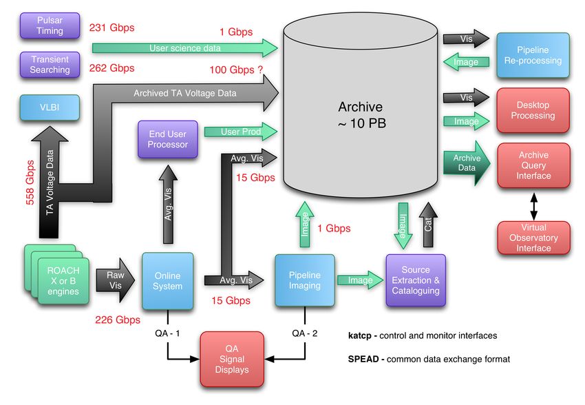
MeerKAT – Data Flow

Images created
With KAT-7
3
Operational nodes
• Cape town
  o   Full primary operations conducted on a service
      observation basis to ensure little or no time on site
• Klerefontein
  o   Maintenance primary node used to monitor and
      plan corrective and preventative maintenance
• Losberg
  o   Primary node during commissioning but will allow
      full operations if needed as well an access point for
      the deployment of user installed hardware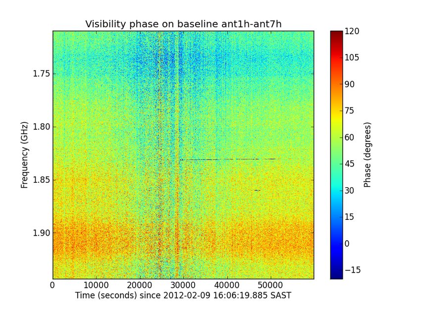
Operational nodes
Operational risks identified
•   Staff at remote sites tend feel isolated
•   Observers lose motivation if they don’t visit the
    telescopes
•   There is a decrease in radio astronomy expertise within
    the broad user community due to less exposure to the
    telescopes
•   Less feedback between site and operator staff leads to
    increase in faults not being quickly resolved
•   Inadequate information flow leads to a loss of “latest
    news” information to observers.
•   Fewer observers at site leads to poorer communication
    with engineers and ultimately a drop in science quality.
•   Scheduling changes on site make it difficult to support
    some types of observing programs.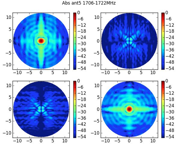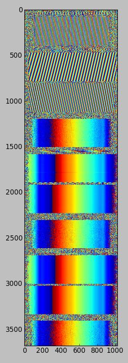
MeerKAT rollout

• 2013 - First qualification dishes deployed
• 2014 - Install test and commission 6
    antennas using a dedicated test system
•   2015 - first official correlator support
•   2015 - 29 antenna at about 3 per month
•   2016 - 29 in 8 months at about 4 per
    month

• Basic rule ... don't' panic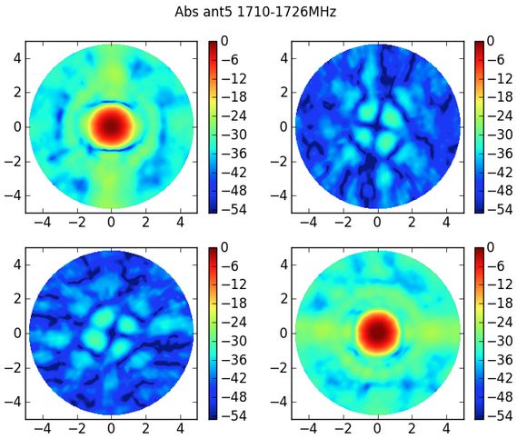
Current commissioning plan
Software tools used

                       SCAPE

                      MeqTrees
Single dish
• Surface accuracy
• Spectral modes
• Pointing calibration
• Primary beam
• Gain calibration
• Polarisation
• Search for unpolarized and polarized, but
stable standard sources
• RFI
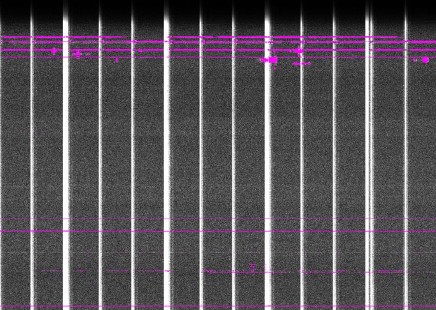
• System linearityKAT-7 – RFI Flagging
KAT-7 – RFI Flagging
Single dish
• Surface accuracy
• Spectral modes
• Pointing calibration
• Primary beam
• Gain calibration
• Polarisation
• Search for unpolarized and polarized, but
    stable standard sources
•   RFI
• System linearitySingle dish
• Surface accuracy
• Spectral modes
• Pointing calibration
• Primary beam
• Gain calibration
• Polarisation
• Search for unpolarized and polarized, but
stable standard sources
• RFI
• System linearitySingle dish
• Surface accuracy
• Spectral modes
• Pointing calibration
• Primary beam
• Gain calibration
• Polarisation
• Search for unpolarized and polarized, but
stable standard sources
• RFI
• System linearitySingle dish
• Surface accuracy
• Spectral modes
• Pointing calibration
• Primary beam
• Gain calibration
• Polarisation
• Search for unpolarized and polarized, but
stable standard sources
• RFI
• System linearitySingle dish
• Surface accuracy
• Spectral modes
• Pointing calibration
• Primary beam
• Gain calibration
• Polarisation
• Search for unpolarized and polarized, but
stable standard sources
• RFI
• System linearitySingle dish
• Surface accuracy
• Spectral modes
• Pointing calibration 0.026 (0.001)
• Primary beam
• Gain calibration 63.9 (3.8)
• Polarisation HH 24.2 (1.4)
• Search for unpolarized and polarized, but
VV 24.4 (1.2)
stable standard sources 938 (65)
• RFI
• System linearitySome problems …
Some problems …
Imaging array
•   Dynamic fringes
•   Antenna location (delay) calibration
•   Phase Closure
•   Measure cross-correlation phase stability
•   Amplitude closure
•   Measure interferometric gain stability
•   Baseline calibration
•   Baseline specific errors
•   Band pass calibration and stability
•   Absolute flux calibration
•   Interferometric polarisation and calibration
Imaging array
Primary
  beam
  correc,on

                      20 arcmins

Primary beam correction was performed in MIRIAD using a 1.3 degree Gaussian (at 1.4 GHz). So far
primary beam correction has not been confirmed in CASA.
Confirma,on
of
beam
center
polariza,on
calibra,on
• Polarization calibration: verification using 3C286 and 3C138 with Miriad
o 12 hour observation, first 6 hours 3C138, then 3C286
o Used 3C286 as gain and polarization calibrator
o Bootstrapped calibration to 3C138 (both sources are not visible at the
same time)
o Miriad flux models for these sources at 1.4 GHz:
§ 3c286: IQUV = 14.6, 0.56, 1.26, 0.0 (flux calibrator)
§ 3c138: IQUV = 8.6, 0.60, -0.27, 0.0 (test source)
o Observed fluxes at 1.4 GHz:
§ 3c286: IQUV = 14.6, 0.56, 1.26, 0.0 as expected
§ 3c138: IQUV = 8.5, 0.58, -0.26, 0.0 calibration confirmed! ☺
o Conclusion is that Miriad works very well with linear hands of polarization
and there is nothing, at this point, that prevents us from doing polarization
imaging once the online system is there.Polarization
Observa(on:
off axis performance
• 3C286,
5x5
raster,
spaced
20
arcmin,
cycled
through
every
30
minutes
• observed
from
source
rise
,ll
set
to
get
good
parallac,c
angle
coverage
• the
centre
poin,ng
was
used
for
calibra,on
(Miriad,
full
polariza,on)
• each
3C286
poin,ng
imaged
individually
and
then
source
from
each
image
copied
into
a
single
fits
file
to
produce
the
images
below
Recommenda(on:
• The
useful
FOV
is
Polarized
  intensity
  3C286

                         The degree of polarization
                         is given by

                         √(Q2 + U2 + V2)/ I2

                         The image (left) confirms
                         that the Mueller matrix is
                         position-dependent and
                         variable across the beam.

                         3C286 has the following
                         polarization parameters

                           I
       Q
        U
      V

                        14.8
     0.56
     1.25
     0
Q
  and
  U
  across
  the
  beam
  3C286


Work is underway to model this variation so as to be able to use a greater portion
of the beam for polarimetry
Amount
  of
  circular
  polariza,on

                 3C286

                             There is no circular
                             polarization at the centre
                             of the beam (expected)
                             but there appears to be
                             leakage off beam centre.

                             Calibration of this is
                             ongoing together with a
                             scheme to do L-Band
                             holography for a
                             measurement of beam
                             characteristics.
Science verification
• Track commissioning parameters with time
• Imaging tests with a range of spectral resolutions,
source complexity, brightness, in single-field
interferometric mode, Dynamic range,
Reproducibility, Noise level (done in CASA and MIRIAD)
• Mosaicing
• Polarization: done on beam center not full beam
• Fine tune observation procedures
• Calibrator surveys
• Full beam calibration (Meqtrees)
• Spectral mode imaging, beamformer and VLBI still
to be confirmedScience verification
• Track commissioning parameters with time
• Imaging tests with a range of spectral resolutions,
source complexity, brightness, in single-field
interferometric mode, Dynamic range,
Reproducibility, Noise level (done in CASA and MIRIAD)
• Mosaicing
• Polarization: done on beam center not full beam
• Fine tune observation procedures
• Calibrator surveys
• Full beam calibration (Meqtrees)
• Spectral mode imaging, beamformer and VLBI still
to be confirmedMilestones for May
$3000 raw voltage capture machine
35Pulsar Timing
Science verification overview
•   Mosaicing / polarization - Maik Wolleben
    o Mosaicing observation planning and reduction confirmed
    o Primary beam correction
•   Spectral lines - Sharmila Goedhart, Brad Frank
    o NGC 3109 HI
    o HI absorption
    o MASERS
•   Continuum observations - Nadeem Oozeer
    o El Gordo
•   Target of opportunity - Tony Foley (TAC)
    o ATEL #3694
The next three slides show the work done to firstly plan mosaicing
observations and second to reduce the data with the required calibration
and corrections applied.
Mosaicing
• Left: KAT-7 Mosaic consisting of 49 Fields, 1.9 GHz
• 10 hours total observing time (including calibrators)
• Right: NVSS at 1.4 GHz shown for comparisonMosaicing
• 1225 fields
• observed during 3
consecutive nights
• size: 10 x 10 deg in
Galactic coordinates
• integration time of each
field: 30 s
• RMS in the final image:
35 mJy/beam in Stokes
I, 20 mJy/beam in
polarized intensity.
Probably due to
ground radiation.
Supernova Remnant SN
1006. (Type 1A
observed in 1006 AD.)Spectral modes
Mode Band Bandwidth Channel Bandwidth Available
Wideband 256 MHz 390.625 kHz Yes
54000 km/s 82 km/s
8k Wideband 256 MHz 48.8 kHz Yes
54000 km/s 10 km/s
OH Spectral Line 6.25 MHz 1.5 kHz In test
(Search) 1300 km/s 0.3 km/s
OH Spectral Line 1.5 MHz 381 Hz In test
(Monitor) 327 km/s 80 m/s
HI Spectral Line 33.3 MHz 4 kHz ~ Oct 2012
7000 km/s 0.84 km/s
Velocities are referenced to HI http://public.ska.ac.za/kat-7HI Velocity Field of NGC 3109
Observed using the wbc8k
mode (10km/s spectral
resolution for HI).
The wbc8k mode was made
available to commissioning to
start testing observation and
reduction strategies for the
narrow band modes while the
other modes are being
developed.
It illustrates the power of the
ROACH design as the time
from conception to first
deployment was one day.PKS1814-637 absorption
This was a short (10
min on source)
observation to
confirm the presence
of the absorption
structure
The expected
absorption line is at
1334 MHz.MASER line for NGC6334 in mode c16n2M4k
MASER lines for NGC6334 in mode
c16n7M4k
Images
  (line
  maps)
  at
  1665
  and

   1667
  MHz
  respec,vely
Overlay
  of
  the
  narrow
  band

contours
  on
  the
  con,nuum
  image
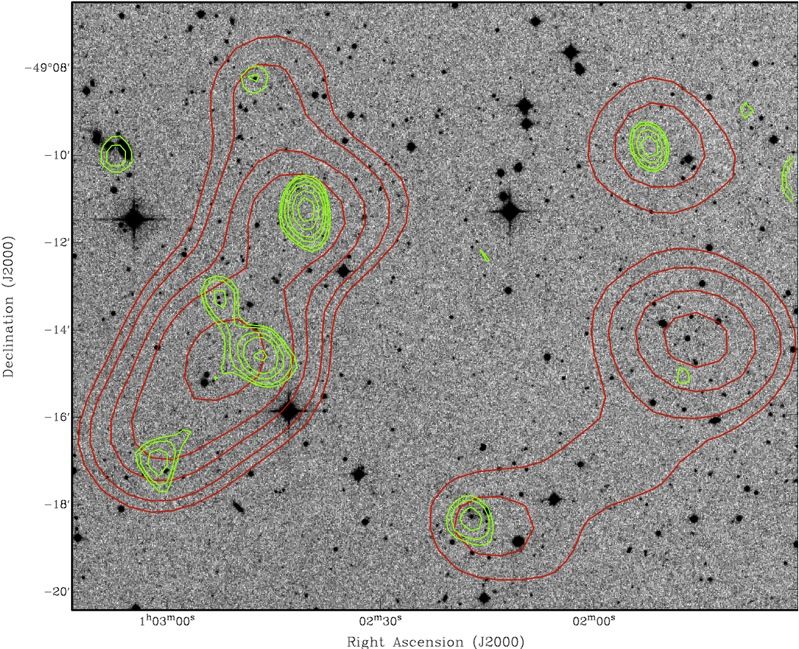
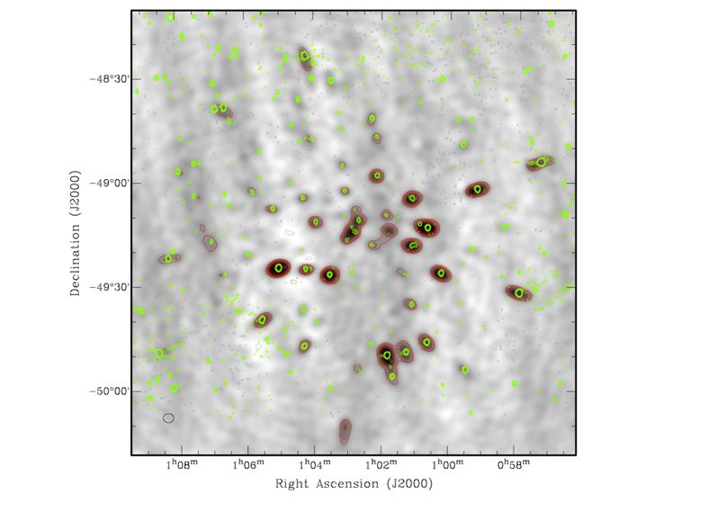
El Gordo (ACT-CL J0102-4915)

                               Aim for observation
                                • check for diffuse
                                  synchrotron emission
                                • check polarization
                                • derive spectral index
                                  and look for break in
                                  spectrum (derive/
                                  confirm physical
                                  parameters)
                                • if no detection: may get
                                  only an upper limit
                                • check expected rms
                                  using long integration.
Comparison with SUMMS
These sources
are just above
the detection
limit of SUMSS
but well detected
with KAT-7PKS 1510-089 - ATEL-3694
Appart from monitoring the source
PKS 1510-089 for the ATEL, the
regular observations have been
used to test the auto-delay (fringe
stopping) functionality and to test
interferometric pointing.Circinus X-1
– Observations of most recent flare show good radio brightening
51Summary • The industrial commissioning plan is being fine tuned • The software tools are in place to characterize the system • The operations and commissioning teams are getting valuable experience in using KAT-7 • We are already doing some continuum/ transient science • Plan for operations …
You can also read