LE910CX LINUX DEVICE DRIVER - APPLICATION NOTE - TELIT TECHNICAL DOCUMENTATION - SIXFAB
←
→
Page content transcription
If your browser does not render page correctly, please read the page content below

LE910Cx Linux Device
     Driver
      Application Note

                     80502NT11769A Rev. 6 – 2022-02-11

Telit Technical Documentation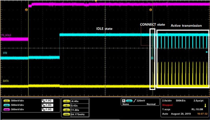
LE910Cx Linux Device Driver Application Note

CONTENTS
CONTENTS                                                               2

APPLICABILITY TABLE                                                    5

1.         INTRODUCTION                                                6
           Scope                                                       6
           Audience                                                    6
           Contact Information, Support                                6
           Symbol Conventions                                          7
           Related Documents                                           7

2.         I2C INTERFACE                                               8
           Using I2C Interface                                         8

3.         HSIC INTERFACE                                             11
           HSIC Signaling                                             11
           Configuring HSIC Master/ Slave Mode                        12

4.         ETHERNET INTERFACE                                         13
           Using SGMII Interface                                      13
4.1.1.     Checking Ethernet Cable Connection Status                  13
4.1.2.     Controlling Ethernet Interface in User Application         14
4.1.3.     Enabling/Disabling the “CLK125” of External Marvell PHY
           (88E1512/5)                                           17

5.         GPIO INTERFACE                                             18
           Using GPIO Interface                                       18
           Using GPIO Interrupt                                       24

6.         SPI INTERFACE                                              27
           Switching from SPI to Aux UART or from Aux UART to SPI 27
           Configuring SPI to Support Multiple CS for Multiple Slave Devices       28
           Configuring SPI to Support Multiple Slave Devices with Interrupt        30
6.3.1.     Getting SPI Interrupt in Application Layer                 32
           Configuring SPI to Support Multiple Slave Ready Signal     35

7.         SD/MMC CARD INTERFACE                                      38

80502NT11769A Rev. 6                  Page 2 of 61                             2022-02-11

                                   Not Subject to NDA
LE910Cx Linux Device Driver Application Note

           Detecting/Mounting of SD/MMC Memory Card      38

8.         UART INTERFACE                                39
           Using #V24CFG Command                         39
           Using #PORTCFG Command                        41

9.         USB INTERFACE                                 43
           Reading Current USB Product ID                43
           Changing USB Composition                      45

10.        EXCEPTION INFORMATION                         47
           Reading Exception Information                 47
           Clearing Stored Information                   47

11.        WLAN INTERFACE                                48
           Setting WLAN SDIO Clock                       48
           Getting Current WLAN SDIO Clock               48

12.        OPM INTERFACE                                 49
           Using OPM Interface                           49
           Configuring PSM DTR and WAKE_LOCK             51

13.        THERMAL SENSOR INTERFACE                      53
           Reading Thermal Sensors                       53

14.        ADC INTERFACE                                 54
           Reading ADC Values                            54

15.        PRODUCT AND SAFETY INFORMATION                55
           Copyrights and Other Notices                  55
15.1.1.    Copyrights                                    55
15.1.2.    Computer Software Copyrights                  55
           Usage and Disclosure Restrictions             56
15.2.1.    License Agreements                            56
15.2.2.    Copyrighted Materials                         56
15.2.3.    High Risk Materials                           56
15.2.4.    Trademarks                                    57
15.2.5.    Third Party Rights                            57

80502NT11769A Rev. 6                  Page 3 of 61            2022-02-11

                                   Not Subject to NDA
LE910Cx Linux Device Driver Application Note

15.2.6.    Waiver of Liability                           57
           Safety Recommendations                        58

16.        GLOSSARY                                      59

17.        DOCUMENT HISTORY                              60

80502NT11769A Rev. 6                 Page 4 of 61             2022-02-11

                                 Not Subject to NDA
LE910Cx Linux Device Driver Application Note
APPLICABILITY TABLE
PRODUCTS
LE910C1-NA
LE910C1-NS
LE910C1-NF
LE910C4-NF
LE910C1-EU
LE910C4-EU
LE910C1-AP
LE910C4-AP
LE910C1-LA
LE910C4-LA
LE910C4-CN
80502NT11769A Rev. 6 Page 5 of 61 2022-02-11
Not Subject to NDALE910Cx Linux Device Driver Application Note
1. INTRODUCTION
Scope
This document provides the descriptions and example code for controlling and
configuring the interfaces.
Audience
This document is intended for Telit customers, especially system integrators, about to
implement their applications using the Telit LE910Cx module.
Contact Information, Support
For general contact, technical support services, technical questions and report of
documentation errors contact Telit Technical Support at:
• TS-EMEA@telit.com
• TS-AMERICAS@telit.com
• TS-APAC@telit.com
• TS-SRD@telit.com
• TS-ONEEDGE@telit.com
Alternatively, use:
https://www.telit.com/contact-us
For detailed information about where you can buy the Telit modules or for
recommendations on accessories and components visit:
https://www.telit.com
Our aim is to make this guide as helpful as possible. Keep us informed of your comments
and suggestions for improvements.
Telit appreciates the user feedback on our information.
80502NT11769A Rev. 6 Page 6 of 61 2022-02-11
Not Subject to NDALE910Cx Linux Device Driver Application Note
Symbol Conventions
Danger: This information MUST be followed, or catastrophic
equipment failure or personal injury may occur.
Warning: Alerts the user on important steps about the module
integration.
Note/Tip: Provides advice and suggestions that may be useful when
integrating the module.
Electro-static Discharge: Notifies the user to take proper grounding
precautions before handling the product.
Table 1: Symbol Conventions
All dates are in ISO 8601 format, that is YYYY-MM-DD.
Related Documents
• LE910Cx AT Commands Reference Guide, 80502ST10950A
• LE910Cx Software User Guide, 1VV0301556
• LE910Cx Hardware User Guide, 1VV0301298
80502NT11769A Rev. 6 Page 7 of 61 2022-02-11
Not Subject to NDALE910Cx Linux Device Driver Application Note
2. I2C INTERFACE
LE910Cx has a single I2C port and only supports master mode.
Figure 1: I2C Master Mode Interface
The following pins on the LE910Cx support an I2C interface:
• B11 - I2C_SCL
• B10 - I2C_SDA
Using I2C Interface
The I2C interface can be used externally by the end-user application. The I2C interface
is accessible from the Linux driver device node(/dev/i2c-4).
Example:
#define I2C_4_DEV_NAME "/dev/i2c-4"
static int i2c_write(int fd,unsigned char slave_addr,unsigned char
reg,unsigned char value)
{
unsigned char outbuf[2];
struct i2c_rdwr_ioctl_data packets;
struct i2c_msg messages[1];
messages[0].addr = slave_addr;
messages[0].flags = 0;
messages[0].len = sizeof(outbuf);
messages[0].buf = outbuf;
/* The first byte indicates which register we'll write */
outbuf[0] = reg;
/*
* The second byte indicates the value to write. Note that for many
80502NT11769A Rev. 6 Page 8 of 61 2022-02-11
Not Subject to NDALE910Cx Linux Device Driver Application Note
* devices, we can write multiple, sequential registers at once by
* simply making outbuf bigger.
*/
outbuf[1] = value;
/* Transfer the i2c packets to the kernel and verify it worked */
packets.msgs = messages;
packets.nmsgs = 1;
if (ioctl(fd, I2C_RDWR, &packets) < 0) {
perror("[I2C] Unable to send data");
return 1;
}
return 0;
}
static int i2c_read(int file,unsigned char addr,unsigned char reg,unsigned
char *val)
{
unsigned char inbuf, outbuf;
struct i2c_rdwr_ioctl_data packets;
struct i2c_msg messages[2];
/*
* In order to read a register, we first do a "dummy write" by writing
* 0 bytes to the register we want to read from. This is similar to
* the packet in set_i2c_register, except it's 1 byte rather than 2.
*/
outbuf = reg;
messages[0].addr = addr;
messages[0].flags = 0;
messages[0].len = sizeof(outbuf);
messages[0].buf = &outbuf;
/* The data will get returned in this structure */
messages[1].addr = addr;
messages[1].flags = I2C_M_RD/* | I2C_M_NOSTART*/;
messages[1].len = sizeof(inbuf);
messages[1].buf = &inbuf;
/* Send the request to the kernel and get the result back */
packets.msgs = messages;
80502NT11769A Rev. 6 Page 9 of 61 2022-02-11
Not Subject to NDALE910Cx Linux Device Driver Application Note
packets.nmsgs = 2;
if(ioctl(file, I2C_RDWR, &packets) < 0) {
perror("[I2C] Unable to send data");
return 1;
}
*val = inbuf;
return 0;
}
int main(int argc, char **argv)
{
int i2c_fd = NULL;
…
// Open a connection to the I2C userspace control file.
if ((i2c_fd = open(I2C_4_DEV_NAME, O_RDWR)) < 0) {
perror("[I2C] Unable to open i2c_4 control file");
exit(1);
}
i2c_write(i2c_fd,…….);
i2c_read(i2c_fd,…….);
close(i2c_fd);
return 0;
}
80502NT11769A Rev. 6 Page 10 of 61 2022-02-11
Not Subject to NDALE910Cx Linux Device Driver Application Note
3. HSIC INTERFACE
LE910Cx provides a two-wire HSIC interface and supports HSIC master/ slave mode.
The LE910Cx HSIC interface supports the following features:
• No hot plug detection
• No hot removal/attachment, interface is always connected
• No high-speed chirp protocols
• HSIC master/slave mode support
HSIC Signaling
Table 2, details all the basic signaling protocols for HSIC. Many signals, such as
CONNECT/RESUME and IDLE/SUSPEND are equivalent.
Bus State Strobe Data Description
IDLE High Low 1 or more Strobe-periods
CONNECT Low High 2 Strobe-periods
RESUME Low High For time periods per USB 2.0 specification
SUSPEND High Low Identical to IDLE state
RESET Low Low Per USB 2.0 specification
Table 2: HSIC Signaling Summary
Figure 2: IDLE to CONNECT Signaling Example (LE910Cx Master and LE910Cx Slave)
80502NT11769A Rev. 6 Page 11 of 61 2022-02-11
Not Subject to NDALE910Cx Linux Device Driver Application Note
Figure 2, illustrates the connect sequence as described below:
• After powering on both HSIC master and slave, master driver is in IDLE bus state.
• Slave monitors the HSIC interface for an IDLE bus state from master.
• Master monitors the HSIC interface for a CONNECT bus state from the slave
device.
• Master detects a CONNECT bus state and starts enumeration.
Configuring HSIC Master/ Slave Mode
The HSIC can be configured as master/slave mode by the end-user application. HSIC
interface can be accessible from Linux driver device node (/dev/m2m_drv_cfg) for
master/ slave mode configuration.
Example:
#define M2M_DRV_CFG_DEV_NAME "/dev/m2m_drv_cfg"
#define M2M_DRV_CFG_MAGIC 't'
#define M2M_DRV_IOCTL_HSIC_GET_MODE _IOR(M2M_DRV_CFG_MAGIC,0,unsigned int)
#define M2M_DRV_IOCTL_HSIC_SET_MODE _IOW(M2M_DRV_CFG_MAGIC,1,unsigned int)
/*open device driver node*/
fd = open(M2M_DRV_CFG_DEV_NAME, O_RDWR);
/* Get the status of HSIC mode
0 – disable HSIC configuration
1 – Enable HSIC master mode
2 – Enable HSIC slave mode
*/
ret = ioctl(fd, M2M_DRV_IOCTL_HSIC_GET_MODE, &hsic_mode);
/* Set HSIC to master mode */
hsic_mode = 1;
ret = ioctl(fd, M2M_DRV_IOCTL_HSIC_GET_MODE, &hsic_mode);
if(ret < 0) {
printf("HSIC mode setting is failed\n");
}
else
{
/*Manual reboot is required after change HSIC mode*/
system("reboot");
}
80502NT11769A Rev. 6 Page 12 of 61 2022-02-11
Not Subject to NDALE910Cx Linux Device Driver Application Note
4. ETHERNET INTERFACE
The LE910Cx has an embedded Ethernet MAC and only supports SGMII interface.
The embedded Ethernet MAC of LE910Cx supports the following features:
• IEEE 802.3 Ethernet 10/100/1000Mbps, SGMII IF
• SGMII interface can be used using external PHY (SGMII to external PHY)
o Giga Ethernet PHY can be used by a transceiver chip. For example, Marvell
88EA1512 PHY chip.
Using SGMII Interface
Before activating the ethernet interface, connect the SGMII interface between LE910Cx
and external PHY chip.
The Ethernet interface on the LE910Cx is activated by a shell script
(/etc/init.d/start_emac_le) , which can be run by an end-user application.
Example:
/etc/init.d/start_emac_le start
4.1.1. Checking Ethernet Cable Connection Status
Ethernet cable connection status can be checked only when the ethernet PHY and MAC
drivers are enabled.
Example:
80502NT11769A Rev. 6 Page 13 of 61 2022-02-11
Not Subject to NDALE910Cx Linux Device Driver Application Note
cat /sys/class/net/eth0/carrier
0 : ethernet cable disconnected state
1 : ethernet cable connected state
4.1.2. Controlling Ethernet Interface in User Application
The ethernet device driver is provided to control ethernet functions by end-user
application. This driver is accessible from Linux driver device node (/dev/m2m_eth).
This driver supports following functions:
• Ethernet mode (LAN mode or WAN mode)
• Ethernet auto connection mode: If auto connection mode is enabled based on the
Ethernet mode setting (LAN or WAN mode), a backhaul connection is established
or a DHCP client is executed.
• Ethernet disable mode: If disabled mode is set, ethernet driver is disabled.
Note: Ethernet PHY chip should be connected.
Example:
#define TELIT_ETH_DEV_NAME "/dev/m2m_eth"
#define TELIT_ETH_CFG_MAGIC 't'
typedef struct {
/* conn_mode variable *./
int conn_mode;
/* 0: etheret interface is disabled
2: automatically ethernet interface is enabled and backhaual connection is
established or DHCP client is executed base on ethernet mode setting (LAN
mode or WAN mode).
*/
/* cid variable for PDP Context Identifier*./
int cid; // range 1-16
}m2m_conn_mode_type;
#define IOCTL_M2M_ETH_SET_CONN_MODE _IOW( TELIT_ETH_CFG_MAGIC, 0,
m2m_conn_mode_type )
#define IOCTL_M2M_ETH_GET_CONN_MODE _IOR( TELIT_ETH_CFG_MAGIC, 1,
m2m_conn_mode_type )
#define IOCTL_M2M_ETH_SET_MODE _IOW( TELIT_ETH_CFG_MAGIC, 2, int)
#define IOCTL_M2M_ETH_GET_MODE _IOR( TELIT_ETH_CFG_MAGIC, 3, int)
typedef enum
80502NT11769A Rev. 6 Page 14 of 61 2022-02-11
Not Subject to NDALE910Cx Linux Device Driver Application Note
{
ETH_CON_MODE_OFF = 0,
ETH_CON_MODE_AUTO = 2
}eth_con_mode_enum;
typedef enum
{
ETH_LAN_MODE = 0,
ETH_WAN_MODE = 1
}eth_mode_enum;
int main(int argc, char *argv[])
{
int fd;
int result;
int mode;
m2m_conn_mode_type m2m_conn_mode = {0,};
fd = open(TELIT_ETH_DEV_NAME,O_RDWR);
if(fd < 0)
{
printf("driver open failed \n");
return -1;
}
/* Get current connection mode
result = ioctl(fd, IOCTL_M2M_ETH_GET_CONN_MODE, &m2m_conn_mode);
if(result < 0)
{
printf("get ethernet connetion mode is failed\n");
}
/* Get current ethernet mode
0 : LAN mode (Deafult)
1 : WAN mode
*/
result = ioctl(fd, IOCTL_M2M_ETH_GET_MODE, &mode);
if(result < 0)
{
printf("ethernet mode setting is failed\n");
}
80502NT11769A Rev. 6 Page 15 of 61 2022-02-11
Not Subject to NDALE910Cx Linux Device Driver Application Note
/* change ethernet mode to WAN mode */
m2m_conn_mode.conn_mode = ETH_CON_MODE_OFF;
result = ioctl(fd, IOCTL_M2M_ETH_SET_CONN_MODE, &m2m_conn_mode);
if(result < 0)
{
printf("ethernet connetion mode setting is failed\n");
}
mode = ETH_WAN_MODE; // WAN mode
result = ioctl(fd, IOCTL_M2M_ETH_SET_MODE, &mode);
if(result < 0)
{
printf("ethernet mode setting is failed\n");
}
/* enable auto connection */
m2m_conn_mode.conn_mode = ETH_CON_MODE_AUTO;
result = ioctl(fd, IOCTL_M2M_ETH_SET_CONN_MODE, &m2m_conn_mode);
if(result < 0)
{
printf("ethernet connetion mode setting is failed\n");
}
/* change ethernet mode to LAN mode */
m2m_conn_mode.conn_mode = ETH_CON_MODE_OFF;
result = ioctl(fd, IOCTL_M2M_ETH_SET_CONN_MODE, &m2m_conn_mode);
if(result < 0)
{
printf("ethernet connetion mode setting is failed\n");
}
mode = ETH_LAN_MODE; // LAN mode
result = ioctl(fd, IOCTL_M2M_ETH_SET_MODE, &mode);
if(result < 0)
{
printf("ethernet mode setting is failed\n");
}
m2m_conn_mode.conn_mode = ETH_CON_MODE_AUTO;
m2m_conn_mode.cid = 1;
result = ioctl(fd, IOCTL_M2M_ETH_SET_CONN_MODE, &m2m_conn_mode);
if(result < 0)
{
printf("ethernet connetion mode setting is failed\n");
80502NT11769A Rev. 6 Page 16 of 61 2022-02-11
Not Subject to NDALE910Cx Linux Device Driver Application Note
}
close(fd)
return 0;
}
4.1.3. Enabling/Disabling the “CLK125” of External Marvell PHY
(88E1512/5)
If you use an external PHY instead of a Marvell PHY, you can control the "CLK125 (Page
2, Reg 16 bit 2)".
Value Description
0 (Default) Enable internally generated 125MHz clock
1 Disable internally generated 125MHz clock
Table 3: Enable/Disable CLK125
For example,
• To enable the CLK125,
If a value of the “/data/marvell_clk” is set to 0 as above, 125MHz clock is
enabled.
• To disable the CLK125,
If a value of the “/data/marvell_clk” is set to 1 as above, 125MHz clock is
disabled.
Note: To control CLK125, it must be set before the ethernet interface
is activated.
The setting is not retained after a firmware update, but it is retained
after a FOTA update.
This feature is only available for the LE910C1-EU (4G+2G) variant.
80502NT11769A Rev. 6 Page 17 of 61 2022-02-11
Not Subject to NDALE910Cx Linux Device Driver Application Note
5. GPIO Interface
LE910Cx provides 10 GPIOs and 8 UART pins, which can be configured as Input and Output
through a Linux device driver.
These GPIO pins allow your application to control external hardware directly from the
GPIO pins, requiring little or no additional hardware.
The LE910Cx supports the following GPIO pins:
Pin Number GPIO/UART Pins
1 GPIO1
2 GPIO2
3 GPIO3
4 GPIO4
5 GPIO5
6 GPIO6
7 GPIO7
8 GPIO8
9 GPIO9
10 GPIO10
20 DCD
21 CTS
22 RI
23 DSR
24 DTR
25 RTS
26 RXD
27 TXD
Table 4: LE910Cx Supported GPIO Pins
To use UART pins as GPIO, use the #V24CFG command to set them to GPIO mode. For
details refer to section 8.1 Using #V24CFG Command.
Using GPIO Interface
The GPIO device driver is provided to allow the common use of GPIOs in various LE910Cx
hardware configurations.
80502NT11769A Rev. 6 Page 18 of 61 2022-02-11
Not Subject to NDALE910Cx Linux Device Driver Application Note
The GPIOs can be used externally by the end-user application. The GPIO interface is
accessible from Linux driver device node (/dev/m2m_gpio).
The following is the list of the supported GPIO I/F parameters:
Parameter Description
Set GPIO modes:
0 - Clear the use of GPIO
1 - Set GPIO direction
2 - Set GPIO output value
3 - Read GPIO value
GPIO pin number:
(TGPIO)1-10, (UART)20-27
GPIO pin direction:
0 - Pin direction is INPUT
1 - Pin direction is OUTPUT
Its meaning depends on setting:
0 - Output pin set to 0 (Low) if =1 - OUTPUT
- Input pin set to 0 (Pull-down) if =0 - INPUT (default)
1 - Output pin set to 1 (High) if =1 - OUTPUT
- Input pin set to 1 (Pull-up) if =0 - INPUT
2 - Input pin set to 2 (No-Pull) if =0 - INPUT
Table 5: Supported GPIO I/F Parameters
Example:
#define GPIO_DEV_PATH "/dev/m2m_gpio"
/* Parameters to be passed through IOCTL */
typedef struct {
unsigned int m2m_gpio_num;
unsigned int m2m_gpio_dir;
unsigned int m2m_gpio_val;
}m2m_gpio_info;
#define M2M_GPIO_MAGIC 'g'
#define IOCTL_M2M_APP_GPIO_CLR _IOW( M2M_APP_GPIO_MAGIC, 0,
m2m_gpio_info )
#define IOCTL_M2M_APP_GPIO_SET_DIR _IOW( M2M_APP_GPIO_MAGIC, 1,
m2m_gpio_info )
#define IOCTL_M2M_APP_GPIO_SET_VAL _IOW( M2M_APP_GPIO_MAGIC, 2,
m2m_gpio_info )
#define IOCTL_M2M_APP_GPIO_GET_VAL _IOW( M2M_APP_GPIO_MAGIC, 3,
m2m_gpio_info )
#define MAX_DEFIEND_TGPIO_NUM 10
#define MIN_UART_GPIO 20
#define MAX_UART_GPIO 27
80502NT11769A Rev. 6 Page 19 of 61 2022-02-11
Not Subject to NDALE910Cx Linux Device Driver Application Note
/* GPIO value parameters for output */
enum
{
M2M_APP_GPIO_OUT_LOW = 0,
M2M_APP_GPIO_OUT_HIGH,
M2M_APP_GPIO_OUT_MAX
};
/* GPIO pull parameters for input */
enum
{
M2M_APP_GPIO_IN_PD = 0,
M2M_APP_GPIO_IN_PU,
M2M_APP_GPIO_IN_NP,
M2M_APP_GPIO_IN_MAX
};
/* GPIO direction parameters */
enum
{
M2M_APP_GPIO_DIR_IN = 0,
M2M_APP_GPIO_DIR_OUT,
M2M_APP_GPIO_DIR_MAX
};
/* GPIO command parameters */
enum
{
M2M_APP_GPIO_MODE_CLR = 0,
M2M_APP_GPIO_MODE_SET_DIR,
M2M_APP_GPIO_MODE_SET_VAL,
M2M_APP_GPIO_MODE_GET_VAL,
M2M_APP_GPIO_MODE_MAX
};
/* GPIO command parameters */
enum
{
M2M_APP_GPIO_MODE_CLR = 0,
M2M_APP_GPIO_MODE_SET_DIR,
M2M_APP_GPIO_MODE_SET_VAL,
M2M_APP_GPIO_MODE_GET_VAL,
M2M_APP_GPIO_MODE_MAX
};
80502NT11769A Rev. 6 Page 20 of 61 2022-02-11
Not Subject to NDALE910Cx Linux Device Driver Application Note
int main(int argc, char *argv[])
{
int dev = 0;
int ret = -1;
m2m_gpio_info *m2m_gpio;
if(atoi(argv[1]) >= M2M_APP_GPIO_MODE_MAX)
{
perror("[GPIO] Mode Parameter out of range \n");
return -1;
}
dev = open(GPIO_DEV_PATH, O_RDWR);
if(dev < 0)
{
perror("[GPIO] driver open failed \n");
return -1;
}
m2m_gpio = (m2m_gpio_info *)malloc(sizeof(m2m_gpio_info));
memset(m2m_gpio, 0x00, sizeof(m2m_gpio_info));
switch(atoi(argv[1]))
{
/* When the use of GPIO is completed, it should be cleared and made
available to other devices */
case M2M_GPIO_MODE_CLR:
if(((atoi(argv[2]) > MAX_DEFINED_TGPIO_NUM) && (atoi(argv[2]) <
MIN_UART_GPIO))
|| (atoi(argv[2]) > MAX_UART_GPIO))
{
perror("[GPIO] GPIO parameter out of range \n");
return -1;
}
m2m_gpio->m2m_gpio_num = atoi(argv[2]);
ret = ioctl(dev, IOCTL_M2M_APP_GPIO_CLR, m2m_gpio);
if(ret)
{
perror("[GPIO] ioctl control failure \n");
80502NT11769A Rev. 6 Page 21 of 61 2022-02-11
Not Subject to NDALE910Cx Linux Device Driver Application Note
return ret;
}
break;
/* Direction should be set to Input (with pull) or Output to control the
GPIO */
case M2M_GPIO_MODE_SET_DIR:
if((((atoi(argv[2]) > MAX_DEFINED_TGPIO_NUM) && (atoi(argv[2]) <
MIN_UART_GPIO))
|| (atoi(argv[2]) > MAX_UART_GPIO))
||(atoi(argv[3]) >= M2M_APP_GPIO_DIR_MAX))
{
perror("[GPIO] GPIO parameter out of range \n");
return -1;
}
m2m_gpio->m2m_gpio_num = atoi(argv[2]);
m2m_gpio->m2m_gpio_dir = atoi(argv[3]);
if(argv[4])
{
if(((atoi(argv[3]) == M2M_APP_GPIO_DIR_IN) && ((atoi(argv[4])) >=
M2M_APP_GPIO_IN_MAX))
|| ((atoi(argv[3]) == M2M_APP_GPIO_DIR_OUT) && ((atoi(argv[4])) >=
M2M_APP_GPIO_OUT_MAX)))
{
perror("[GPIO] GPIO parameter out of range \n");
return -1;
}
else
{
m2m_gpio->m2m_gpio_val = atoi(argv[4]);
}
}
else
{
if(atoi(argv[3]) == M2M_APP_GPIO_DIR_IN)
{
m2m_gpio->m2m_gpio_val = M2M_APP_GPIO_IN_PD; // default pull-
down
}
else
{
80502NT11769A Rev. 6 Page 22 of 61 2022-02-11
Not Subject to NDALE910Cx Linux Device Driver Application Note
perror("[GPIO] Invalid parameter \n");
return -1;
}
}
ret = ioctl(dev, IOCTL_M2M_APP_GPIO_SET_DIR, m2m_gpio);
if(ret)
{
perror("[GPIO] ioctl control failure \n");
return ret;
}
break;
/* When setting GPIO's output values (High / Low), direction should be
set to OUTPUT first. */
case M2M_GPIO_MODE_SET_VAL:
if((((atoi(argv[2]) > MAX_DEFINED_TGPIO_NUM) && (atoi(argv[2]) <
MIN_UART_GPIO))
|| (atoi(argv[2]) > MAX_UART_GPIO))
|| (atoi(argv[3]) >= M2M_APP_GPIO_OUT_MAX))
{
perror("[GPIO] GPIO parameter out of range \n");
return -1;
}
m2m_gpio->m2m_gpio_num = atoi(argv[2]);
m2m_gpio->m2m_gpio_dir = M2M_APP_GPIO_DIR_OUT;
m2m_gpio->m2m_gpio_val = atoi(argv[3]);
ret = ioctl(dev, IOCTL_M2M_APP_GPIO_SET_VAL, m2m_gpio);
if(ret)
{
perror("[GPIO] ioctl control failure \n");
return ret;
}
break;
/* Read the current GPIO pin status */
case M2M_GPIO_MODE_GET_VAL:
if(((atoi(argv[2]) > MAX_DEFINED_TGPIO_NUM) && (atoi(argv[2]) <
MIN_UART_GPIO))
80502NT11769A Rev. 6 Page 23 of 61 2022-02-11
Not Subject to NDALE910Cx Linux Device Driver Application Note
|| (atoi(argv[2]) > MAX_UART_GPIO))
{
perror("[GPIO] GPIO parameter out of range \n");
return -1;
}
m2m_gpio->m2m_gpio_num = atoi(argv[2]);
m2m_gpio->m2m_gpio_dir = M2M_GPIO_DIR_IN;
ret = ioctl(dev, IOCTL_M2M_APP_GPIO_GET_VAL, m2m_gpio);
if(ret)
{
perror("[GPIO] ioctl control failure \n");
return ret;
}
break;
default:
break;
}
free(m2m_gpio);
close(dev);
return ret;
}
Using GPIO Interrupt
The GPIO-keys module allows a Linux-based application, to listen to GPIO interrupts. This
can be accomplished using a GPIO 1-10.
Application can then listen to “/dev/input/event1” to get the interrupt and the interrupt
data.
Several GPIOs are able to wake up the system from sleep. When using such a GPIO with
the GPIO-KEYS driver, any interrupt on this line will wake the system. Using a GPIO that
is not capable of waking up the system with the GPIO-KEYS driver will PREVENT THE
SYSTEM FROM GOING INTO SLEEP (the logic is very simple: if there is an interrupt
pending on a non-wakeup capable GPIO, do not go to sleep).
The GPIO-Keys module has two parameters:
80502NT11769A Rev. 6 Page 24 of 61 2022-02-11
Not Subject to NDALE910Cx Linux Device Driver Application Note
• tgpios – An array of tgpios to listen on. For example, tgpios=4,5 causes the driver
to listen to tgpio4 and tgpio5.
• pull_arr – An optional array of pull settings to apply to each tgpio used. The
following options are available:
o 0 – No Pull
o 1 – Pull Up
o 2 – Pull Down
o 3 – Default
Insert command for the GPIO-Keys module:
“insmod /data/gpio-keys tgpios=[,,,,] pull_arr=[,,,,]”
Remove command for the GPIO-Keys module:
“rmmod gpio-keys”
Example:
To start the gpio-keys driver listen on tgpio4 (no pull) and tgpio5 (pull up), use the
following command:
“insmod /data/gpio-keys tgpios=4,5 pull_arr=0,1”
And if the gpio-keys driver listen on tgpio4 (pull up), use the following command:
“insmod /data/gpio-keys tgpios=4 pull_arr=1”
Note: The number of tgpios parameters must match the number of
pull_arr parameters, otherwise pull_arr is totally ignored.
Note: The following GPIOs are wake up capable (All other GPIOs are
not wakeup capable):
• GPIO1
• GPIO5
• GPIO8
80502NT11769A Rev. 6 Page 25 of 61 2022-02-11
Not Subject to NDALE910Cx Linux Device Driver Application Note
Warning: Some GPIOs (GPIO1, GPIO5 ~ 9) should not be pulled high
externally (by the carrier board) during module power on procedure.
Pulling those pads high during module power up might lead to
unwanted/non-operational boot mode.
Refer Hardware User Guide for more details.
Note: GPIO1 and GPIO8 each have "SLED" and "SWREADYEN"
functions by default, so in order to use the GPIO interface, the
functions should be disabled through AT command first.
m2m_gpio and GPIO-Keys cannot use the same GPIO at the same
time, but in the case of GPIO with interrupt set by GPIO-Keys, it is
possible to read the value of GPIO through m2m_gpio.
80502NT11769A Rev. 6 Page 26 of 61 2022-02-11
Not Subject to NDALE910Cx Linux Device Driver Application Note
6. SPI INTERFACE
LE910Cx provides a 4-wire SPI (Serial Peripheral Interface) and the H/W Pins of SPI are
shared with Aux UART, so SPI and Aux UART cannot be used simultaneously.
LE910Cx provides the device driver node(/dev/m2m_drv_cfg) to switch from Aux UART to
SPI or from SPI to Aux UART and this device driver node is used to configure SPI CS,
interrupt, and slave ready GPIO by end-user application.
SPI interrupt and SPI slave ready GPIO are optional function.
The table below lists the supported GPIO pins for SPI CS, SPI interrupt or SPI slave ready
on LE910Cx.
GPIO Pins Descriptions
1 GPIO1
2 GPIO2
3 GPIO3
4 GPIO4
5 GPIO5
6 GPIO6
7 GPIO7
8 GPIO8
9 GPIO9
10 GPIO10
Table 6: LE910Cx Supported GPIO Pins for SPI Interface
Switching from SPI to Aux UART or from Aux UART to SPI
The driver device node (/dev/m2m_drv_cfg) can be used to switch from SPI to Aux UART
or from Aux UART to SPI by the end-user application.
Example:
#define M2M_DRV_CFG_DEV_NAME "/dev/m2m_drv_cfg"
#define M2M_DRV_CFG_MAGIC 't'
#define M2M_DRV_IOCTL_GET_SPI_STATUS _IOR(M2M_DRV_CFG_MAGIC, 2, unsigned
int)
#define M2M_DRV_IOCTL_SET_SPI_STATUS _IOW(M2M_DRV_CFG_MAGIC, 3, unsigned
int)
int main(int argc, char *argv[])
80502NT11769A Rev. 6 Page 27 of 61 2022-02-11
Not Subject to NDALE910Cx Linux Device Driver Application Note
{
int fd = 0;
unsigned int spi_status = 0;
fd = open(M2M_DRV_CFG_DEV_NAME, O_RDWR);
if(fd < 0)
{
printf("%s driver open failed \n", M2M_DRV_CFG_DEV_NAME);
return -1;
}
/*Get SPI status 1: Enable SPI, 0: Disable SPI*/
if(ioctl(fd, M2M_DRV_IOCTL_GET_SPI_STATUS, &spi_status) < 0)
{
printf("Unable to get current status\n");
}
spi_status = 1; //1: Switch from Aux UART to SPI | 0: Switch from SPI to Aux
UART.
if(ioctl(fd, M2M_DRV_IOCTL_SET_SPI_STATUS, &spi_status) < 0)
{
printf("Unable to set status\n");
}
else{
system(“reboot”);
}
close(fd);
return 0;
Configuring SPI to Support Multiple CS for Multiple Slave
Devices
The driver device node (/dev/m2m_drv_cfg) can be used to support multiple slave devices
by the end-user application.
When the multiple SPI CS pins are configured by the end-user application, the end-user
application must execute “reboot”. From the next boot-up, LE910Cx configures the
multiple CS pins and creates SPI device driver nodes (/dev/spievB.0, /dev/spidevB.1, and
/dev/spidevB.2).
80502NT11769A Rev. 6 Page 28 of 61 2022-02-11
Not Subject to NDALE910Cx Linux Device Driver Application Note
If SPI CS pins are not configured, the SPI master of LE910Cx controls the dedicated
SPI_CS_pin for SPI device driver nodes (/dev/spievB.0, /dev/spidevB.1, and
/dev/spidevB.2). If you only want to use one SPI slave device, use "/dev/spidevB.0."
The end user should check SPI device driver nodes.
Example:
#define M2M_DRV_CFG_DEV_NAME "/dev/m2m_drv_cfg"
#define M2M_DRV_CFG_MAGIC 't'
#define M2M_DRV_IOCTL_GET_SPI_STATUS _IOR(M2M_DRV_CFG_MAGIC, 2, unsigned
int)
#define M2M_DRV_IOCTL_SET_SPI_STATUS _IOW(M2M_DRV_CFG_MAGIC, 3, unsigned
int)
#define M2M_DRV_IOCTL_GET_SPI_CFG_INFO _IOR( M2M_DRV_CFG_MAGIC, 4,
m2m_spi_info_type[3] )
#define M2M_DRV_IOCTL_SET_SPI_CFG_INFO _IOW( M2M_DRV_CFG_MAGIC, 5,
m2m_spi_info_type[3] )
/* Parameters to be passed through IOCTL */
typedef struct {
unsigned int cs_gpio;
unsigned int int_gpio;
unsigned int slave_ready_gpio;
}m2m_spi_info_type;
int main(int argc, char *argv[])
{
int fd = 0;
m2m_spi_info_type m2m_spi_info[3]={0,};
unsigned int spi_status = 0;
fd = open(M2M_DRV_CFG_DEV_NAME, O_RDWR);
if(fd < 0)
{
printf("%s driver open failed \n", M2M_DRV_CFG_DEV_NAME);
return -1;
}
if(ioctl(fd, M2M_DRV_IOCTL_GET_SPI_STATUS, &spi_status) < 0)
{
printf("Unable to get spi_status\n");
}
if(spi_status == 0)
80502NT11769A Rev. 6 Page 29 of 61 2022-02-11
Not Subject to NDALE910Cx Linux Device Driver Application Note
spi_status = 1; // If SPI is enabled, from next boot-up, SPI device driver
nodes are created.
if(ioctl(fd, M2M_DRV_IOCTL_SET_SPI_STATUS, &spi_status) < 0)
{
printf("unable to set spi_status\n");
}
/*Get current SPI configuration information*/
if(ioctl(fd, M2M_DRV_IOCTL_GET_SPI_CFG_INFO, &m2m_spi_info) < 0)
{
printf("unable to get SPI configuration information\n");
}
/*Set SPI configuration information*/
m2m_spi_info[0].cs_gpio = 0;
m2m_spi_info[0].int_gpio = 0;
m2m_spi_info[0].slave_ready_gpio = 0;
m2m_spi_info[1].cs_gpio = 8;
m2m_spi_info[1].int_gpio = 0;
m2m_spi_info[1].slave_ready_gpio = 0;
m2m_spi_info[2].cs_gpio = 9;
m2m_spi_info[2].int_gpio = 0;
m2m_spi_info[2].slave_ready_gpio = 0;
if(ioctl(fd, M2M_DRV_IOCTL_SET_SPI_CFG_INFO, &m2m_spi_info) < 0)
{
printf("unable to set SPI configuration information\n");
}
else
{
system(“reboot”);
}
close(fd);
return 0;
Configuring SPI to Support Multiple Slave Devices with
Interrupt
The device driver node(/dev/m2m_drv_cfg) can be used to support multiple slave devices
with interrupt by the end-user application.
80502NT11769A Rev. 6 Page 30 of 61 2022-02-11
Not Subject to NDALE910Cx Linux Device Driver Application Note
If SPI interrupts are configured by the end-user application, the end-user application
must execute “reboot”. From the next boot-up, LE910Cx configures SPI interrupts with
“IRQF_TRIGGER_RISING | IRQF_TRIGGER_FALLING” properties.
Example:
#define M2M_DRV_CFG_DEV_NAME "/dev/m2m_drv_cfg"
#define M2M_DRV_CFG_MAGIC 't'
#define M2M_DRV_IOCTL_GET_SPI_STATUS _IOR(M2M_DRV_CFG_MAGIC, 2, unsigned
int)
#define M2M_DRV_IOCTL_SET_SPI_STATUS _IOW(M2M_DRV_CFG_MAGIC, 3, unsigned
int)
#define M2M_DRV_IOCTL_GET_SPI_CFG_INFO _IOR( M2M_DRV_CFG_MAGIC, 4,
m2m_spi_info_type[3] )
#define M2M_DRV_IOCTL_SET_SPI_CFG_INFO _IOW( M2M_DRV_CFG_MAGIC, 5,
m2m_spi_info_type[3] )
/* Parameters to be passed through IOCTL */
typedef struct {
unsigned int cs_gpio;
unsigned int int_gpio;
unsigned int slave_ready_gpio;
}m2m_spi_info_type;
int main(int argc, char *argv[])
{
int fd = 0;
m2m_spi_info_type m2m_spi_info[3]={0,};
unsigned int spi_status = 0;
fd = open(M2M_DRV_CFG_DEV_NAME, O_RDWR);
if(fd < 0)
{
printf("%s driver open failed \n", M2M_DRV_CFG_DEV_NAME);
return -1;
}
if(ioctl(fd, M2M_DRV_IOCTL_GET_SPI_STATUS, &spi_status) < 0)
{
printf("Unable to get spi_status\n");
}
if(spi_status == 0)
80502NT11769A Rev. 6 Page 31 of 61 2022-02-11
Not Subject to NDALE910Cx Linux Device Driver Application Note
spi_status = 1; // If SPI is enabled, from next boot-up, SPI device driver
nodes are created.
if(ioctl(fd, M2M_DRV_IOCTL_SET_SPI_STATUS, &spi_status) < 0)
{
printf("unable to set spi_status\n");
}
/*Get current SPI configuration information*/
if(ioctl(fd, M2M_DRV_IOCTL_GET_SPI_CFG_INFO, &m2m_spi_info) < 0)
{
printf("unable to get SPI configuration information\n");
}
/*Set SPI configuration information*/
m2m_spi_info[0].cs_gpio = 0;
m2m_spi_info[0].int_gpio = 2;
m2m_spi_info[0].slave_ready_gpio = 0;
m2m_spi_info[1].cs_gpio = 8;
m2m_spi_info[1].int_gpio = 3;
m2m_spi_info[1].slave_ready_gpio = 0;
m2m_spi_info[2].cs_gpio = 9;
m2m_spi_info[2].int_gpio = 4;
m2m_spi_info[2].slave_ready_gpio = 0;
if(ioctl(fd, M2M_DRV_IOCTL_SET_SPI_CFG_INFO, &m2m_spi_info) < 0)
{
printf("unable to set SPI configuration information\n");
}
else
{
system(“reboot”);
}
close(fd);
return 0;
6.3.1. Getting SPI Interrupt in Application Layer
Example:
#include
80502NT11769A Rev. 6 Page 32 of 61 2022-02-11
Not Subject to NDALE910Cx Linux Device Driver Application Note
#include
#include
#include
#include
#include
#include
#include
#include
#include
#include
#include
#include
#include
#include
#include
#include
int main(int argc, char *argv[])
{
int fd = 0;
int ret;
uint8_t mode = 0; // please set mode according to slave device
environment.
uint32_t speed = 50000000; // please set speed according to slave device
environment.
uint8_t bits_per_word = 8;
struct pollfd poll_fds[1];
if (access("/sys/devices/78b9000.spi/spi_master", F_OK) != 0)
{
fd = open(“/dev/spidev1.0”, O_RDWR);
if(fd < 0)
{
printf("spidev1.0 driver open failed \n");
return -1;
}
}
else{
fd = open(“/dev/spidev2.0”, O_RDWR);
if(fd < 0)
{
printf("spidev2.0 driver open failed \n");
80502NT11769A Rev. 6 Page 33 of 61 2022-02-11
Not Subject to NDALE910Cx Linux Device Driver Application Note
return -1;
}
}
/*
* spi mode
*/
ret = ioctl(fd, SPI_IOC_WR_MODE, &mode);
if (ret == -1) printf("cant set WR spi mode");
ret = ioctl(fd, SPI_IOC_RD_MODE, &mode);
if (ret == -1) printf("can't set RD spi mode");
/*
* bits per word
*/
ret = ioctl(fd, SPI_IOC_WR_BITS_PER_WORD, &bits_per_word);
if (ret == -1) printf("can't set WR bits per word");
ret = ioctl(this->fd, SPI_IOC_RD_BITS_PER_WORD, &bits_per_word);
if (ret == -1) printf("can't set RD bits per word");
/*
* max speed hz
*/
ret = ioctl(fd, SPI_IOC_WR_MAX_SPEED_HZ, &speed);
if (ret == -1) printf"can't WR set max speed hz");
ret = ioctl(fd, SPI_IOC_RD_MAX_SPEED_HZ, &speed);
if (ret == -1) printf("can't RD set max speed hz");
/*
* Waiting SPI interrupt singal using poll function.
*/
poll_fds[0].fd = fd;
poll_fds[0].events = POLLIN | POLLRDNORM;
while (1)
{
ret = poll(poll_fds, 1, -1);
if(ret > 0){
printf(“ Interrupt is happened\n");
// Read SPI data. If SPI read is called, SPI driver clears the
poll event.
80502NT11769A Rev. 6 Page 34 of 61 2022-02-11
Not Subject to NDALE910Cx Linux Device Driver Application Note
break;
}
}
close(fd);
return 0;
}
Configuring SPI to Support Multiple Slave Ready Signal
The device driver node(/dev/m2m_drv_cfg) can be used to support multiple slave devices
with interrupt by the end-user application.
Whenever an SPI slave device is not ready to transmit data on SPI bus, it turns GPIO
output to high state. When LE910Cx receives a high state from an SPI slave device, it waits
for 5 sec for low state from SPI slave device. If SPI slave device does not turn to a GPIO
low state, error occur in LE910Cx during SPI read/ write operation.
Example:
#define M2M_DRV_CFG_DEV_NAME "/dev/m2m_drv_cfg"
#define M2M_DRV_CFG_MAGIC 't'
#define M2M_DRV_IOCTL_GET_SPI_STATUS _IOR(M2M_DRV_CFG_MAGIC, 2, unsigned
int)
#define M2M_DRV_IOCTL_SET_SPI_STATUS _IOW(M2M_DRV_CFG_MAGIC, 3, unsigned
int)
#define M2M_DRV_IOCTL_GET_SPI_CFG_INFO _IOR( M2M_DRV_CFG_MAGIC, 4,
m2m_spi_info_type[3] )
#define M2M_DRV_IOCTL_SET_SPI_CFG_INFO _IOW( M2M_DRV_CFG_MAGIC, 5,
m2m_spi_info_type[3] )
/* Parameters to be passed through IOCTL */
typedef struct {
unsigned int cs_gpio;
unsigned int int_gpio;
unsigned int slave_ready_gpio;
}m2m_spi_info_type;
int main(int argc, char *argv[])
{
int fd = 0;
m2m_spi_info_type m2m_spi_info[3]={0,};
unsigned int spi_status = 0;
80502NT11769A Rev. 6 Page 35 of 61 2022-02-11
Not Subject to NDALE910Cx Linux Device Driver Application Note
fd = open(M2M_DRV_CFG_DEV_NAME, O_RDWR);
if(fd < 0)
{
printf("%s driver open failed \n", M2M_DRV_CFG_DEV_NAME);
return -1;
}
if(ioctl(fd, M2M_DRV_IOCTL_GET_SPI_STATUS, &spi_status) < 0)
{
printf("Unable to get spi_status\n");
}
if(spi_status == 0)
spi_status = 1; // If SPI is enabled, from next boot-up, SPI device driver
nodes are created.
if(ioctl(fd, M2M_DRV_IOCTL_SET_SPI_STATUS, &spi_status) < 0)
{
printf("unable to set spi_status\n");
}
/*Get current SPI configuration information*/
if(ioctl(fd, M2M_DRV_IOCTL_GET_SPI_CFG_INFO, &m2m_spi_info) < 0)
{
printf("unable to get SPI configuration information\n");
}
/*Set SPI configuration information*/
m2m_spi_info[0].cs_gpio = 0;
m2m_spi_info[0].int_gpio = 2;
m2m_spi_info[0].slave_ready_gpio = 5;
m2m_spi_info[1].cs_gpio = 8;
m2m_spi_info[1].int_gpio = 3;
m2m_spi_info[1].slave_ready_gpio = 6;
m2m_spi_info[2].cs_gpio = 9;
m2m_spi_info[2].int_gpio = 4;
m2m_spi_info[2].slave_ready_gpio = 7;
if(ioctl(fd, M2M_DRV_IOCTL_SET_SPI_CFG_INFO, &m2m_spi_info) < 0)
{
printf("unable to set SPI configuration information\n");
}
else
80502NT11769A Rev. 6 Page 36 of 61 2022-02-11
Not Subject to NDALE910Cx Linux Device Driver Application Note
{
system(“reboot”);
}
close(fd);
return 0;
80502NT11769A Rev. 6 Page 37 of 61 2022-02-11
Not Subject to NDALE910Cx Linux Device Driver Application Note
7. SD/MMC CARD INTERFACE
LE910Cx provides an SD port that supports the SD3.0 specification and can be used with
standard SD/MMC memory cards.
Detecting/Mounting of SD/MMC Memory Card
1. When an SD/MMC memory card is inserted, the device node is created
automatically as shown below.
2. Once the device node appears, run the below command from an end-user
application or from the adb shell.
Example:
mount -t vfat /dev/mmcblk0 /mnt/sdcard
3. Verify that the file system has been mounted (refer to the last line in the below
output):
4. To unmount the SD/MMC memory card from /mnt/sdcard run the below
command:
Example:
umount /mnt/sdcard
5. Remove the SD/MMC memory card from the card slot.
80502NT11769A Rev. 6 Page 38 of 61 2022-02-11
Not Subject to NDALE910Cx Linux Device Driver Application Note
8. UART INTERFACE
LE910Cx supports two UART interfaces. Main UART pins include TX data (TXD), RX data
(RXD), Request To Send (RTS), Clear To Send (CTS), Data Terminal Ready (DTR), Data
Carrier Detect (DCD), and Ring Indicator (RI).
Note: The SPI hardware pins are shared with Aux UART, hence SPI
and Aux UART cannot be used simultaneously.
The following functions are supported by the UART interface:
• AT#V24CFG and AT#V24 command
• AT#PORTCFG command
Refer to AT commands Reference Guide for more details.
Using #V24CFG Command
#V24CFG command is used to configure the serial interface pins as GPIO.
To support V24CFG command, a device driver is provided, which can be used externally
by the end-user application. The device driver is accessible from Linux driver device node
(/dev/m2m_drv_cfg).
Example:
#define M2M_DRV_CFG_DEV_NAME "/dev/m2m_drv_cfg"
#define M2M_DRV_CFG_MAGIC 't'
#define M2M_DRV_IOCTL_GET_V24_CFG _IOR( M2M_DRV_CFG_MAGIC, 6, unsigned
int [8] )
#define M2M_DRV_IOCTL_SET_V24_CFG _IOW( M2M_DRV_CFG_MAGIC, 7, unsigned
int [8] )
int main(int argc, char *argv[])
{
int fd = 0;
int result = 0
unsigned int v24cfg_mode[8]={0,};
fd = open(M2M_DRV_CFG_DEV_NAME, O_RDWR);
if(fd < 0)
{
printf("%s driver open failed \n", M2M_DRV_CFG_DEV_NAME);
return -1;
}
80502NT11769A Rev. 6 Page 39 of 61 2022-02-11
Not Subject to NDALE910Cx Linux Device Driver Application Note
//Get the current setting information
result = ioctl(fd, M2M_DRV_IOCTL_GET_V24_CFG, &v24cfg_mode);
if(result < 0)
{
printf("Failed read V24CFG info\n");
}
/*
v24cfg_mode[0] : DCD
v24cfg_mode[1] : CTS
v24cfg_mode[2] : RI
v24cfg_mode[3] : DSR
v24cfg_mode[4] : DTR
v24cfg_mode[5] : RTS
v24cfg_mode[6] : RXD
v24cfg_mode[7] : TXD
if the value for each index in the array is 0,1 or 2:
0 : AT commands serial port mode
1 : GPIO mode Pins directly controlled by #V24 command
2 : GPIO kernel mode Pins directly controlled by kernel GPIO
driver.
*/
v24cfg_mode[0] = 2;
v24cfg_mode[1] = 2;
v24cfg_mode[2] = 2;
v24cfg_mode[3] = 2;
v24cfg_mode[4] = 2;
v24cfg_mode[5] = 2;
v24cfg_mode[6] = 2;
v24cfg_mode[7] = 2;
result = ioctl(fd, M2M_DRV_IOCTL_SET_V24_CFG, &v24cfg_mode);
if(result < 0)
{
printf("Failed V24CFG setting\n");
}
else{
printf("V24CFG setting is succeeded\n");
system("reboot"); //module must be reboot, the pins configuration is
applied next power cycle
}
close(fd);
80502NT11769A Rev. 6 Page 40 of 61 2022-02-11
Not Subject to NDALE910Cx Linux Device Driver Application Note
return 0;
}
Using #PORTCFG Command
#PORTCFG supports the following variants.
Variants Descriptions
Variant 0 USIF0, USB0, and USB1 are connected to AT port.
Variant 3 USIF0, USIF1, and USB0 are connected to AT port.
Variant 8 USB0 and USB1 are connected to AT port.
USIF0, USB0 and USB1 are connected to AT port.
Variant 11
USIF1 is used for NMEA Sentences.
Variant 14(default) USIF0, USIF1, USB0 and USB1 are connected to AT port.
USIF0, USB0 and USB1 are connected to AT port.
Variant 15
USIF1 is connected to console port.
USIF0, USB0 and USB1 are connected to AT port.
Variant 16
USIF1 is used for external BT UART supporting.
Table 6 : #PORTCFG Command
To support #PORTCFG command, device driver is provided, and the device driver can be
used externally by the end-user application. The device driver is accessible from Linux
driver device node(/dev/m2m_drv_cfg).
Example:
#define M2M_DRV_CFG_DEV_NAME "/dev/m2m_drv_cfg"
#define M2M_DRV_CFG_MAGIC 't'
#define M2M_DRV_IOCTL_GET_PORTCFG _IOR( M2M_DRV_CFG_MAGIC, 8,
m2m_portcfg_info_type )
#define M2M_DRV_IOCTL_SET_PORTCFG _IOW( M2M_DRV_CFG_MAGIC, 9, unsigned int)
typedef struct {
unsigned int act_variant;
unsigned int req_variant;
}m2m_portcfg_info_type;
int main(int argc, char *argv[])
{
int fd = 0;
int result = 0
m2m_portcfg_info_type m2m_portcfg_info ={0,};
unsigned int req_variant = 0;
80502NT11769A Rev. 6 Page 41 of 61 2022-02-11
Not Subject to NDALE910Cx Linux Device Driver Application Note
fd = open(M2M_DRV_CFG_DEV_NAME, O_RDWR);
if(fd < 0)
{
printf("%s driver open failed \n", M2M_DRV_CFG_DEV_NAME);
return -1;
}
//Get the current setting information
result = ioctl(fd, M2M_DRV_IOCTL_GET_PORTCFG, &m2m_portcfg_info);
if(result < 0)
{
printf("Failed read PORTCFG info\n");
}
/*
if the value of m2m_portcfg_info.act_variant is 0,3,8,11,14,15 or 16.
0: USIF0, USB0, and USB1 are connected to AT port
3: USIF0, USIF1, and USB0 are connected to AT port
8: USB0 and USB1 are connected to AT port.
11: USIF0, USB0 and USB1 are connected to AT port and USIF1 is used for
NMEA Setences.
14: USIF0, USIF1, USB0 and USB1 is connected to AT port.
15: USIF0, USB0 and USB1 are connected to AT port and USIF1 is connected
to console port.
16: USIF0, USB0 and USB1 are connected to AT port and USIF1 is used for
external BT UART supporting
*/
//Set the variant of #PORTCFG
req_variant = 15;
result = ioctl(fd, M2M_DRV_IOCTL_SET_PORTCFG, &req_variant);
if(result < 0)
{
printf("Failed PORTCFG setting\n");
}
else{
printf("PORTCFG setting is succeeded\n");
system("reboot"); //module must be reboot, the port configuration is
applied next power cycle
}
close(fd);
return 0;
}
80502NT11769A Rev. 6 Page 42 of 61 2022-02-11
Not Subject to NDALE910Cx Linux Device Driver Application Note
9. USB INTERFACE
LE910Cx includes a USB2.0 compliant Universal Serial Bus (USB) Transceiver, which
operates at USB 2.0 High-speed (480Mbits/sec). By default, the module is configured as
a USB peripheral mode.
The table below lists the available USB compositions:
Product ID Description
1200 None mode
1201 DIAG + ADB + RMNET + NMEA + MODEM + MODEM + SAP
1203 RNDIS + DIAG + ADB + NMEA + MODEM + MODEM + SAP
1204 DIAG + ADB + MBIM + NMEA + MODEM + MODEM + SAP
1205 MBIM
1206 DIAG + ADB + ECM + NMEA + MODEM + MODEM + SAP
1250 RMNET + NMEA + MODEM + MODEM + SAP
1251 RNDIS + NMEA + MODEM + MODEM + SAP
1252 MBIM + NMEA + MODEM + MODEM + SAP
1253 ECM + NMEA + MODEM +MODEM + SAP
1254 MODEM + MODEM
1255 NMEA + MODEM + MODEM + SAP
1230 DIAG + ADB + RMNET + AUDIO + NMEA + MODEM + MODEM + SAP
1231 RNDIS + DIAG + ADB + AUDIO + NMEA + MODEM + MODEM + SAP
1260 DIAG + ADB + RMNET + NMEA + MODEM + MODEM + SAP
1261 DIAG + ADB + RMNET + NMEA + MODEM + MODEM + SAP
1262 DIAG + ADB + RMNET + NMEA + MODEM + MODEM + AUX
Table 7: LE910Cx USB Compositions
For more information, refer to #USBCFG command on AT commands Reference Guide.
Reading Current USB Product ID
Example:
include
#include
#include
#include
#include
80502NT11769A Rev. 6 Page 43 of 61 2022-02-11
Not Subject to NDALE910Cx Linux Device Driver Application Note
#include
#include
#include
#include
#define CURRENT_CONFIGURATION_FILE_NAME "/data/usb/boot_hsusb_composition"
static int get_current_usb_configuration_name_id(char
*current_configuration_file_name);
static int get_current_usb_configuration_name_id(char
*current_configuration_file_name)
{
char *composition_name_ptr = NULL;
int composition_id = 0;
char *linkname = NULL;
ssize_t r = 0;
if(current_configuration_file_name == NULL)
{
printf("current_configuration_file_name NULL pointer");
return -1;
}
linkname = malloc(PATH_MAX + 1);
if (linkname == NULL) {
printf("insufficient memory can't malloc\n");
return -1;
}
memset(linkname, 0, (PATH_MAX + 1));
r = readlink(current_configuration_file_name, linkname, PATH_MAX);
if (r < 0) {
printf("readlink failed. r = %d\n", r);
free(linkname);
return -1;
}
if (r < 4) {
printf("File link error. r = %d\n", r);
free(linkname);
return -1;
80502NT11769A Rev. 6 Page 44 of 61 2022-02-11
Not Subject to NDALE910Cx Linux Device Driver Application Note
}
//Last 4 charachters on file path will be composition file name,
//which are also the composition number and the information we're after.
linkname[r] = '\0';
composition_name_ptr = &linkname[r-4];
printf("composition_name_ptr = %s\n", composition_name_ptr);
composition_id = atoi(composition_name_ptr);
printf("Current composition is %d\n", composition_id);
free(linkname);
return composition_id;
}
int main(int argc, char *argv[])
{
int pid = 0;
pid =
get_current_usb_configuration_name_id(CURRENT_CONFIGURATION_FILE_NAME);
printf("Current USB product ID = %d \n", pid);
return 0;
}
Changing USB Composition
Example:
#include
#include
#include
#include
#include
#include
#include
#include
#include
#define MAX_COMMAND_LEN 256
#define USB_COMPOSITION_SET_COMMAND "usb_composition "
static int change_usb_composition(int new_composition_name_id);
80502NT11769A Rev. 6 Page 45 of 61 2022-02-11
Not Subject to NDALE910Cx Linux Device Driver Application Note
static int change_usb_composition(int new_composition_name_id)
{
char change_usb_composition_command[MAX_COMMAND_LEN] = {0};
int res = 0;
snprintf (change_usb_composition_command, MAX_COMMAND_LEN, "%s %d n y
n n", USB_COMPOSITION_SET_COMMAND, new_composition_name_id);
res = system(change_usb_composition_command);
if(res == 0)
{
printf("USB composition was changed. Need to reboot.");
return 0;
}
else
{
printf("Cannot execute %s command, returned value = %d",
change_usb_composition_command, res);
return -1;
}
}
int main(int argc, char *argv[])
{
int pid = 0;
int result = 0;
/*
To change the USB composition to PID_1203 or the other PID, please set
to 1203 or the other PID as below.
*/
pid = 1203; // RNDIS + DIAG + ADB + NMEA + MODEM + MODEM + SAP
result = change_usb_composition(pid);
if(result == 0)
{
system ("reboot");
} else{
printf(“cannot change usb composition”);
}
return 0;
}
80502NT11769A Rev. 6 Page 46 of 61 2022-02-11
Not Subject to NDALE910Cx Linux Device Driver Application Note
10. EXCEPTION INFORMATION
Reading Exception Information
You can read the exception information from the below path:
/sys/class/misc/telit_rawdata/fatal_info
Example:
~ # cat /sys/class/misc/telit_raw_data/fatal_info
#EXCEPINFO:
1,"M0F.220006","2019/11/05","02:48:20",1704,"dsatm2mgen.c","Assertion 0
failed:PC 837E6EDC:LR 837E6454:SP 869FE0B8"
#EXCEPINFO: 2,"","","",0,"",""
#EXCEPINFO: 3,"","","",0,"",""
#EXCEPINFO: 4,"","","",0,"",""
#EXCEPINFO: 5,"","","",0,"",""
Clearing Stored Information
You can clear the stored exception information by writing ‘0’ to below path:
/sys/class/misc/telit_rawdata/fatal_info
Example:
~ # cat /sys/class/misc/telit_raw_data/fatal_info
#EXCEPINFO:
1,"M0F.220006","2019/11/05","02:48:20",1704,"dsatm2mgen.c","Assertion 0
failed:PC 837E6EDC:LR 837E6454:SP 869FE0B8"
#EXCEPINFO: 2,"","","",0,"",""
#EXCEPINFO: 3,"","","",0,"",""
#EXCEPINFO: 4,"","","",0,"",""
#EXCEPINFO: 5,"","","",0,"",""
~ # echo 0 > /sys/class/misc/telit_raw_data/fatal_info
~ # cat /sys/class/misc/telit_raw_data/fatal_info
#EXCEPINFO: 1,"","","",0,"",""
#EXCEPINFO: 2,"","","",0,"",""
#EXCEPINFO: 3,"","","",0,"",""
#EXCEPINFO: 4,"","","",0,"",""
#EXCEPINFO: 5,"","","",0,"",""
80502NT11769A Rev. 6 Page 47 of 61 2022-02-11
Not Subject to NDALE910Cx Linux Device Driver Application Note
11. WLAN INTERFACE
Setting WLAN SDIO Clock
You can set SDIO clock for the WLAN interface with write value to the below file.
The changed value will be applied when the WLAN is started. If this value changes while
the WLAN is already turned on, it must be restarted.
Note: The changed value by the user will be maintained even after
module reboot or FW update.
/sys/class/misc/telit_raw_data/wlan_max_clock
The value is mapped as shown in the table below.
Value Frequency
1 400khz
2 20Mhz
3 25Mhz
4 50Mhz
5 100Mhz
6 (default) 200Mhz
Table 8: WLAN SDIO Clock Value
For example, if you like to set the SDIO clock to 50Mhz,
Getting Current WLAN SDIO Clock
To get the current and applied maximum SDIO clock for the WLAN interface, use the
following file:
/sys/class/misc/telit_raw_data/wlan_max_clock
The currently configured value will be returned.
For example, If the 50Mhz has been configured,
80502NT11769A Rev. 6 Page 48 of 61 2022-02-11
Not Subject to NDALE910Cx Linux Device Driver Application Note
12. OPM INTERFACE
LE910Cx module provides an OPM (Operating Mode) interface to control the module's
operating mode and the Power Saving Mode (PSM).
This interface allows you to change the behavior of your modem through a user
application on Linux, which provides the same behavior and modes as the +CFUN
command.
Note:
For more information on AT+CFUN command, refer to AT commands
Reference Guide.
For more information on Power Saving Mode, refer to PSM Application
Note for more details)
Using OPM Interface
The device driver node (/dev/telit_opm) can be used to control modem operating mode by
the user application, and the parameters for each mode are as follows.
The table below lists the supported operating modes for the LE910Cx.
Operating Mode Description
1 Mobile full functionality with power saving disabled
2 Disable TX (Not support)
4 Disable both TX and RX
5 Mobile full functionality with power saving enabled
6 Mobile reboot
7 Offline mode
8 FTM
Table 9: LE910Cx Supported Operating Modes
Example:
#define OPM_DEV_PATH "/dev/telit_opm"
#define M2M_OPM_MAGIC 'o'
#define IOCTL_M2M_OPM_SET _IOW( M2M_OPM_MAGIC, 0, unsigned int )
#define IOCTL_M2M_OPM_GET _IOW( M2M_OPM_MAGIC, 1, unsigned int )
#define M2M_OPM_MODE_MAX 9
80502NT11769A Rev. 6 Page 49 of 61 2022-02-11
Not Subject to NDALE910Cx Linux Device Driver Application Note
/* OPM command parameters */
enum
{
M2M_OPM_CMD_SET_VAL = 0,
M2M_OPM_CMD_GET_VAL,
M2M_OPM_CMD_MAX
};
int main(int argc, char *argv[])
{
int dev = 0;
int ret = 0;
unsigned int opm_val=0;
if(atoi(argv[1]) >= M2M_OPM_CMD_MAX)
{
perror("[OPM] cmd parameter out of range \n");
return -1;
}
if(argc == 3)
{
opm_val = atoi(argv[2]);
}
dev = open(OPM_DEV_PATH, O_RDWR);
if(dev < 0)
{
perror("[OPM] driver open failed \n");
return -1;
}
switch(atoi(argv[1]))
{
case M2M_OPM_CMD_SET_VAL:
ret = ioctl(dev, IOCTL_M2M_OPM_SET, opm_val);
break;
case M2M_OPM_CMD_GET_VAL:
ret = ioctl(dev, IOCTL_M2M_OPM_GET, &opm_val);
80502NT11769A Rev. 6 Page 50 of 61 2022-02-11
Not Subject to NDALE910Cx Linux Device Driver Application Note
if(ret)
return -1;
else
return opm_val;
break;
default:
break;
}
close(dev);
return ret;
}
Configuring PSM DTR and WAKE_LOCK
The module can enter the power saving mode when all the below condition are met.
• USB disconnected
• UART's DTR off
• No WAKE_LOCK
To satisfy a PSM condition, users who are unable to control the DTR-pin on an external
device can turn off a UART DTR by configuring it as a GPIO via AT#V24CFG (/dev/m2m drv
cfg). For more information, see chapter 8 UART Interface.
In addition, if the user wants to maintain wake-up status after setting the operating-mode
5 (+CFUN=5) is set, the user application can use WAKE_LOCK to prevent the module from
entering Sleep, as shown below.
Example:
// Set WAKE_LOCK for keeping wake-up
system(“echo telit_opm > /sys/power/wake_lock”)
// Set WAKE_UNLOCK for entering PSM
system(“echo telit_opm > /sys/power/wake_unlock”)
80502NT11769A Rev. 6 Page 51 of 61 2022-02-11
Not Subject to NDAYou can also read