PROFINET Interface Absolute PROFINET Encoders
←
→
Page content transcription
If your browser does not render page correctly, please read the page content below
TECHNICAL REFERENCE MANUAL

PROFINET Interface
Absolute PROFINET® Encoders

                                           1-800-366-5412 | ENCODER.COM | SALES@ENCODER.COM

                                                                                                                                  Page 1
1-800-366-5412 | encoder.com | sales@encoder.com                                         © 2023 Encoder Products Company, REV 03/14/2023
PROFINET® Interface                                      TECHNICAL REFERENCE MANUAL

©2023 Encoder Products Company. All rights reserved.

Encoder Products Company
464276 Highway 95 South
Sagle, Idaho 83860
USA

Phone: (208) 263-8541
Fax: (208) 263-0541
Email (USA): support@encoder.com
Email (other countries): sales@encoder.com
Website: encoder.com

PROFINET® is a registered trademark and patented technology, licensed by
PU (PROFIBUS & PROFINET) International.

Warranty waiver, right of amendment, copyright:
Encoder Products Company (EPC) accepts no liability or warranty for the correctness of this manual, or for
any direct or indirect damage that may arise from use of it. In the pursuit of constant innovation and coop-
eration with customers, EPC reserves the right to amend technical data or content at any time without prior
notice to customers.

                                                                     EPC Technical Reference Manual – Absolute Encoders with PROFINET Interface
1-800-366-5412 | encoder.com | sales@encoder.com   PAGE 2 OF 64                               © 2023 Encoder Products Company, REV 03/14/2023
PROFINET® Interface                                                                                                  TECHNICAL REFERENCE MANUAL

Table of contents
1. Introduction ���������������������������������������������������������������������������������������� 6                4.7.2 Warnings���������������������������������������������������������������������������������������� 27
  1.1 About this manual���������������������������������������������������������������������������6                       4.7.3 G1_XIST2 error codes������������������������������������������������������������������ 27
   1.1.1 Explanation of symbols used in this manual���������������������������6
   1.1.2 What is not in this manual:����������������������������������������������������������7                      5. Web server������������������������������������������������������������������������������������������28
  1.2 Products supported������������������������������������������������������������������������7                      5.1 General �������������������������������������������������������������������������������������������� 28
  1.3 Specifications������������������������������������������������������������������������������������7              5.2 Information ������������������������������������������������������������������������������������ 28
  1.4 Scope of delivery �����������������������������������������������������������������������������8                  5.2.1 Overview���������������������������������������������������������������������������������������� 28
                                                                                                                         5.2.2 Diagnosis ��������������������������������������������������������������������������������������� 30
2. Safety information ���������������������������������������������������������������������������� 8                    5.2.3 Versions������������������������������������������������������������������������������������������ 31
  2.1 General �����������������������������������������������������������������������������������������������8         5.3 Configuration��������������������������������������������������������������������������������� 32
  2.2 Intended use��������������������������������������������������������������������������������������8               5.3.1 Network������������������������������������������������������������������������������������������ 32
  2.3 Safe working��������������������������������������������������������������������������������������8               5.3.2 Encoder ������������������������������������������������������������������������������������������ 33
  2.4 Disposal�����������������������������������������������������������������������������������������������9          5.3.3 Firmware update ������������������������������������������������������������������������� 33
                                                                                                                        5.4 License information��������������������������������������������������������������������� 37
3. Device description����������������������������������������������������������������������������� 9                   5.5 Contact �������������������������������������������������������������������������������������������� 38
  3.1 General �����������������������������������������������������������������������������������������������9
  3.2 PROFINET��������������������������������������������������������������������������������������������9          6. Commissioning���������������������������������������������������������������������������������38
  3.3 Principles of EPC’s A58E-series encoders ������������������������������ 10                                       6.1 General information �������������������������������������������������������������������� 38
   3.3.1 Single turn – ST���������������������������������������������������������������������������� 10               6.2 Integrating into a TIA project ��������������������������������������������������� 38
   3.3.2 Multi-turn – MT���������������������������������������������������������������������������� 10                6.3 Scaling function����������������������������������������������������������������������������� 50
   3.3.3 Direction of rotation������������������������������������������������������������������� 10                    6.3.1 Example scaling function single turn 16-bit to 12-bit������ 50
   3.3.4 Preset ���������������������������������������������������������������������������������������������� 11       6.3.2 Example scaling function multi-turn������������������������������������� 52
   3.3.5 Scaling��������������������������������������������������������������������������������������������� 11        6.3.3 Executing a preset (Telegram 81-84 + 59000)��������������������� 54
  3.4 Connection assignments for PROFINET encoders�������������� 12                                                     6.3.4 Resetting a preset (Telegram 81-84 + 59000)��������������������� 57
   3.4.1 Bus cover with 3 x M12x1 ��������������������������������������������������������� 12                          6.3.5 Executing a preset (Telegram 86-89)������������������������������������� 57
  3.5 LEDs and signaling����������������������������������������������������������������������� 12                     6.4 Integration into a Step 7 project ��������������������������������������������� 58
  3.6 MAC address and IP address ����������������������������������������������������� 13
                                                                                                                      7. Technical Data �����������������������������������������������������������������������������������63
4. PROFINET��������������������������������������������������������������������������������������������14              7.1 Properties ��������������������������������������������������������������������������������������� 63
  4.1 Summary of functions����������������������������������������������������������������� 14                         7.2 Dimensions�������������������������������������������������������������������������������������� 63
  4.2 GSDML modules���������������������������������������������������������������������������� 14
  4.3 Signals����������������������������������������������������������������������������������������������� 14      8. Technical support�����������������������������������������������������������������������������64
  4.4 Structure of the signals �������������������������������������������������������������� 15
  4.5 Telegrams����������������������������������������������������������������������������������������� 21
  4.6 Parameters�������������������������������������������������������������������������������������� 22
   4.6.1 Description of the most important parameters������������������ 23
    4.6.1.1 Code sequence������������������������������������������������������������������������ 23
    4.6.1.2 Class 4 functionality��������������������������������������������������������������� 23
    4.6.1.3 G1_XIST1 preset control������������������������������������������������������ 24
    4.6.1.4 Scaling function control ������������������������������������������������������ 24
    4.6.1.5 Preset value������������������������������������������������������������������������������ 24
    4.6.1.6 Measuring units per revolution������������������������������������������ 24
    4.6.1.7 Total measuring range in measuring units��������������������� 24
    4.6.1.8 Velocity measuring units������������������������������������������������������ 24
    4.6.1.9 Offset value������������������������������������������������������������������������������ 25
    4.6.1.10 Hysteresis position��������������������������������������������������������������� 25
    4.6.1.11 Extrapolation position ������������������������������������������������������� 25
    4.6.1.12 Filter max. RPM��������������������������������������������������������������������� 26
    4.6.1.13 Filter position������������������������������������������������������������������������ 26
    4.6.1.14 Filter speed���������������������������������������������������������������������������� 26
  4.7 Warnings and errors �������������������������������������������������������������������� 27
   4.7.1 Errors������������������������������������������������������������������������������������������������ 27

                                                                                                                                                  EPC Technical Reference Manual – Absolute Encoders with PROFINET Interface
1-800-366-5412 | encoder.com | sales@encoder.com                                                        PAGE 3 OF 64                                                       © 2023 Encoder Products Company, REV 03/14/2023
PROFINET® Interface                                                                                                                    TECHNICAL REFERENCE MANUAL

Index of Figures
Figure 3.1: EPC EtherCAT-ready encoders with PROFINET IRT bus covers����������������������������������������������������� 9
Figure 5.1: Web server – overview����������������������������������������������������������������������������������������������������������������������������28
Figure 5.2: Diagnostic page����������������������������������������������������������������������������������������������������������������������������������������30
Figure 5.3: Versions���������������������������������������������������������������������������������������������������������������������������������������������������������31
Figure 5.4: Network settings���������������������������������������������������������������������������������������������������������������������������������������32
Figure 5.5: Encoder information �������������������������������������������������������������������������������������������������������������������������������33
Figure 5.6: Firmware update���������������������������������������������������������������������������������������������������������������������������������������33
Figure 5.7: Firmware update – choose file ������������������������������������������������������������������������������������������������������������34
Figure 5.8: Firmware update – transferring file���������������������������������������������������������������������������������������������������35
Figure 5.9: Firmware update – successful���������������������������������������������������������������������������������������������������������������35
Figure 5.10: Firmware update – failed���������������������������������������������������������������������������������������������������������������������36
Figure 5.11: License information ������������������������������������������������������������������������������������������������������������������������������37
Figure 6.1: Switching to project view ����������������������������������������������������������������������������������������������������������������������39
Figure 6.2: Manage device description file (GSD)������������������������������������������������������������������������������������������������40
Figure 6.3: Installing GSDML���������������������������������������������������������������������������������������������������������������������������������������40
Figure 6.4: Switch to Devices & Network����������������������������������������������������������������������������������������������������������������41
Figure 6.5: Hardware catalog ������������������������������������������������������������������������������������������������������������������������������������42
Figure 6.6: Network view ���������������������������������������������������������������������������������������������������������������������������������������������43
Figure 6.7: Change device name�������������������������������������������������������������������������������������������������������������������������������43
Figure 6.8: Select telegrams����������������������������������������������������������������������������������������������������������������������������������������43
Figure 6.9: Change the I/O addresses����������������������������������������������������������������������������������������������������������������������44
Figure 6.10: Download to device ������������������������������������������������������������������������������������������������������������������������������44
Figure 6.11: Assigning device names ����������������������������������������������������������������������������������������������������������������������45
Figure 6.12: Name and PG interface������������������������������������������������������������������������������������������������������������������������46
Figure 6.13: Accessible nodes�������������������������������������������������������������������������������������������������������������������������������������47
Figure 6.14: Online status information ������������������������������������������������������������������������������������������������������������������48
Figure 6.15: PLC variables���������������������������������������������������������������������������������������������������������������������������������������������49
Figure 6.16: Show all������������������������������������������������������������������������������������������������������������������������������������������������������49
Figure 6.17: Default tag table ������������������������������������������������������������������������������������������������������������������������������������50
Figure 6.18: Example of commissioning ����������������������������������������������������������������������������������������������������������������50
Figure 6.19: Assembly parameters���������������������������������������������������������������������������������������������������������������������������51
Figure 6.20: Default assembly parameters 16-bit single turn������������������������������������������������������������������������51
Figure 6.21: Configuration of 12-bit single turn with scaling�������������������������������������������������������������������������52
Figure 6.22: Example of commissioning ����������������������������������������������������������������������������������������������������������������52
Figure 6.23: Device overview – MAP������������������������������������������������������������������������������������������������������������������������53
Figure 6.24: Assembly parameters���������������������������������������������������������������������������������������������������������������������������53
Figure 6.25: Configuration of 360 Steps/revolution and 10 revolutions ����������������������������������������������������54
Figure 6.26: Set STW2_ENC bit 10 to TRUE������������������������������������������������������������������������������������������������������������55
Figure 6.27: Set G1_STW bit 13 to TRUE������������������������������������������������������������������������������������������������������������������55
Figure 6.28: G1_STW Bit 11 default 0 = absolute������������������������������������������������������������������������������������������������56
Figure 6.29: Set and reset G1_STW Bit 12���������������������������������������������������������������������������������������������������������������56
Figure 6.30: SIMATIC Manager ����������������������������������������������������������������������������������������������������������������������������������58
Figure 6.31: Installing the GSDML file ���������������������������������������������������������������������������������������������������������������������59
Figure 6.32: Hardware catalog����������������������������������������������������������������������������������������������������������������������������������59
Figure 6.33: Hardware view����������������������������������������������������������������������������������������������������������������������������������������60
Figure 6.34: Select via single mouse click���������������������������������������������������������������������������������������������������������������60
Figure 6.35: Slot 1, highlighted green ���������������������������������������������������������������������������������������������������������������������61
Figure 6.36: Slot 1.2 with inserted telegram 81���������������������������������������������������������������������������������������������������61
Figure 6.37: Change the I/O addresses �������������������������������������������������������������������������������������������������������������������61
Figure 6.38: “Addresses” tab ���������������������������������������������������������������������������������������������������������������������������������������61
Figure 6.39: Save and transmit – Download to module ����������������������������������������������������������������������������������62
Figure 6.40: Variable table ������������������������������������������������������������������������������������������������������������������������������������������62
Figure 6.41: HEX position value���������������������������������������������������������������������������������������������������������������������������������62

                                                                                                                                                                         EPC Technical Reference Manual – Absolute Encoders with PROFINET Interface
1-800-366-5412 | encoder.com | sales@encoder.com                                                                    PAGE 4 OF 64                                                                  © 2023 Encoder Products Company, REV 03/14/2023
PROFINET® Interface                                                                                                                      TECHNICAL REFERENCE MANUAL

Index of Tables
Table 3.1: Pin connection assignment���������������������������������������������������������������������������������������������������������������������12
Table 3.2: LED signals����������������������������������������������������������������������������������������������������������������������������������������������������13
Table 4.1: Functions�������������������������������������������������������������������������������������������������������������������������������������������������������14
Table 4.2: GSDML modules������������������������������������������������������������������������������������������������������������������������������������������14
Table 4.3: Signals ������������������������������������������������������������������������������������������������������������������������������������������������������������15
Table 4.4: Structure of signal 6 NIST_A�������������������������������������������������������������������������������������������������������������������15
Table 4.5: Structure of signal 6 NIST_B�������������������������������������������������������������������������������������������������������������������15
Table 4.6: Structure of signal 9 G1_STW����������������������������������������������������������������������������������������������������������������16
Table 4.7: Structure of signal 10 G1_ZSW��������������������������������������������������������������������������������������������������������������17
Table 4.8: Structure of signal 11 G1_XIST1������������������������������������������������������������������������������������������������������������17
Table 4.9: Structure of signal 12 G1_XIST2������������������������������������������������������������������������������������������������������������17
Table 4.10: Structure of signal 39 G1_XIST3 ���������������������������������������������������������������������������������������������������������18
Table 4.11: Structure of signal 80 STW2_ENC������������������������������������������������������������������������������������������������������18
Table 4.12: Structure of signal 81 ZSW2_ENC������������������������������������������������������������������������������������������������������19
Table 4.13: Structure of signal 238(60000) G1_XIST1_PRESET_B����������������������������������������������������������������19
Table 4.14: Structure of signal G1_XIST1_PRESET_B1���������������������������������������������������������������������������������������20
Table 4.15: Structure of signal G1_XIST1_PRESET_C����������������������������������������������������������������������������������������20
Table 4.16: Structure of signal 60001 DEBUG_STW�������������������������������������������������������������������������������������������20
Table 4.17: Structure of signal 60002 DEBUG_ZSW�������������������������������������������������������������������������������������������21
Table 4.18: Telegrams ���������������������������������������������������������������������������������������������������������������������������������������������������21
Table 4.19: Supported parameters���������������������������������������������������������������������������������������������������������������������������23
Table 4.20: Velocity measuring units������������������������������������������������������������������������������������������������������������������������24
Table 4.21: Hysteresis position������������������������������������������������������������������������������������������������������������������������������������25
Table 4.22: Extrapolation position ���������������������������������������������������������������������������������������������������������������������������25
Table 4.23: Filter max. RPM������������������������������������������������������������������������������������������������������������������������������������������26
Table 4.24: Filter position���������������������������������������������������������������������������������������������������������������������������������������������26
Table 4.25: Filter speed �������������������������������������������������������������������������������������������������������������������������������������������������27
Table 4.26: Errors ������������������������������������������������������������������������������������������������������������������������������������������������������������27
Table 4.27: Warnings������������������������������������������������������������������������������������������������������������������������������������������������������27
Table 4.28: G1_XIST2 error codes������������������������������������������������������������������������������������������������������������������������������27
Table 6.1: Data content for Example������������������������������������������������������������������������������������������������������������������������54

                                                                                                                                                                          EPC Technical Reference Manual – Absolute Encoders with PROFINET Interface
1-800-366-5412 | encoder.com | sales@encoder.com                                                                     PAGE 5 OF 64                                                                  © 2023 Encoder Products Company, REV 03/14/2023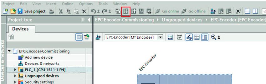
PROFINET® Interface                                                               TECHNICAL REFERENCE MANUAL

1. Introduction
1.1 About this manual
This technical manual describes the configuration and mounting possibilities for absolute-value encoders with a PROFINET
interface produced by Encoder Products Company (EPC). It supplements the other publicly available EPC documents, e.g. data
sheets, assembly instructions, leaflets, catalogs and flyers.
Ensure that you read the manual before provisioning – check beforehand that you have the latest version of the manual.
When reading, pay particular attention to the information, important notices and warnings that are marked with the
corresponding symbols (see 1.1.1).
This manual is intended for persons with technical knowledge in the handling of sensors, PROFINET IRT interfaces and automation
elements. If you do not have any experience in this field, request the assistance of experienced personnel before proceeding.
Keep the information provided with our product in a safe place so that you can refer to it later as necessary.

                             • The contents of this manual are arranged with practical use in mind.
                             • All of the information in the following sections is required to get the best possible use
                               out of the equipment, and should be read through thoroughly.

1.1.1 Explanation of symbols used in this manual

                                             • The INFO symbol is placed next to a section of text that is particularly informative or
                                               important for what to do next with the equipment.

                                             • The IMPORTANT symbol is shown next to a section of text that describes a method for
                                               solving a particular problem.

                                             • The WARNING symbol is placed next to a section of text that should be paid particular
                                               attention to in order to ensure the correct use of the equipment and to protect
                                               against danger.

                                                                                                   EPC Technical Reference Manual – Absolute Encoders with PROFINET Interface
1-800-366-5412 | encoder.com | sales@encoder.com                        PAGE 6 OF 64                                        © 2023 Encoder Products Company, REV 03/14/2023
PROFINET® Interface                                                     TECHNICAL REFERENCE MANUAL

1.1.2 What is not in this manual:
   • Basic information about automation technology
   • System planning
   • Risks (availability, safety)
   • Shielding concepts
   • Reflections
   • Repeaters
   • Network configuration
   • Bus cycle times
   • FMA management systems
   • Transmission services
   • Telegram types

1.2 Products supported
This manual relates to the following encoder types produced by Encoder Products Company:

   • Model A58HE – PROFINET absolute blind hollow bore encoder with bus cover
   • Model A58SE – PROFINET absolute shaft encoder, synchro or clamping flange, standard, heavy-duty, or compact, with
     bus cover

                             • EPC’s PROFINET product range can be found on our website: encoder.com

1.3 Specifications
An encoder is a sensor that is designed to detect angular positions (single turn) and revolutions (multi-turn). The measured data
and variables are processed by the encoder and provided as electrical output signals for the connected peripherals.
Patented technologies for single turn and for multi-turn are used in the A58SE and A58HE series encoders. As a result, these
encoders from EPC are maintenance-free and environmentally friendly.
The encoders whose article descriptions are listed in Section 1.2 communicate via the PROFINET IRT interface.

                                                                                       EPC Technical Reference Manual – Absolute Encoders with PROFINET Interface
1-800-366-5412 | encoder.com | sales@encoder.com               PAGE 7 OF 64                                     © 2023 Encoder Products Company, REV 03/14/2023
PROFINET® Interface                                                       TECHNICAL REFERENCE MANUAL

1.4 Scope of delivery
The scope of delivery depends on the product variants and the details of your order. Before commissioning, check the contents of
the delivery for completeness.
As a rule, the Model A58HE and A58SE products have a PROFINET IRT interface includes the following items:

   • Model A58HE or A58SE with PROFINET IRT (with bus cover)
   • Assembly instructions

2. Safety information
2.1 General

                             • When provisioning the encoder, ensure that you observe the assembly instructions,
                               manual and data sheet.
                             • Failure to observe the safety instructions may lead to malfunctions, property damage
                               and personal injury!
                             • Observe the operating instructions provided by the machine’s manufacturer.

2.2 Intended use
Rotary encoders are components that are intended for installation in machines. Before commissioning (operation in accordance
with the intended use), it must be determined that the machine as a whole corresponds to the EMC and Machine Directive.
A rotary encoder is a sensor that is designed to detect angular positions and revolutions and must only be used for this purpose.
EPC Automation manufactures and distributes encoders for use in non-safety-relevant industrial applications.

                             • The encoder must not be operated outside the specified limit parameters (see
                               product datasheet).

2.3 Safe working
The installation and mounting of the encoder must only be carried out by a qualified electrician. For the construction of electrical
installations, all relevant national and international regulations must be strictly observed. Failure to commission the encoder
correctly may result in malfunction or failure.

                                                                                           EPC Technical Reference Manual – Absolute Encoders with PROFINET Interface
1-800-366-5412 | encoder.com | sales@encoder.com                 PAGE 8 OF 64                                       © 2023 Encoder Products Company, REV 03/14/2023
PROFINET® Interface                                                       TECHNICAL REFERENCE MANUAL

                             • All electrical components must be tested before commissioning.
                             • Appropriate safety measures must be taken to ensure that no persons are harmed
                               and no damage to the system or operating equipment occurs in the event of a failure
                               or malfunction.

2.4 Disposal
Devices that are no longer needed or are defective must be disposed by the user in proper compliance with the country-specific
laws. It must be taken into consideration that this is a special waste of electronics and that disposal is not permitted via normal
household waste.

3. Device description
3.1 General
Various mechanical variants of the Model A58SE and A58HE-series encoders with PROFINET IRT are available. The required variant
is determined by the need for a bus cover, the flange design and the shaft type (solid or hollow). The size is specified as 58 mm by
the diameter at the flange. The following figure shows examples of A58SE/HE-series encoders with PROFINET IRT.
The solid or hollow shaft is connected to the rotating component whose angular position or rotational speed is to be measured.
Cable or plug outlets create the interface for connection to the PROFINET network. The status LEDs mounted in the cover signal
the various encoder states during operation. They assist with configuration of the encoder and troubleshooting in the field. The
flange holes or supplied spring sheets are used for attachment to the machine and during the respective application.

Figure 3.1: EPC EtherCAT-ready encoders with PROFINET IRT bus covers

From left to right: A58SE with clamping flange; A58SE with synchro flange; A58SE heavy-duty; A58SE compact; A58HE (blind
hollow bore)

3.2 PROFINET
PROFINET is distributed by the PROFIBUS User Organization (PNO) as a successor to Profibus. PROFINET is the standard interface
for industrial Ethernet. PROFINET provides similar functionality to Profibus, but extends these by firmware upgrades.

                                                                                          EPC Technical Reference Manual – Absolute Encoders with PROFINET Interface
1-800-366-5412 | encoder.com | sales@encoder.com                PAGE 9 OF 64                                       © 2023 Encoder Products Company, REV 03/14/2023
PROFINET® Interface TECHNICAL REFERENCE MANUAL
Established IT standards are used for the transfer of information. UDP, IP and XML form the basis for this. XML is used as a
description language in the device profile (abbreviated to “GSDML file”). In order for the devices to exchange their data via
IP – process data (cyclic) and parameter data (acyclic) – a unique name must be assigned to each PROFINET node during
configuration. The control can only assign an IP address to the node via this name.
PROFINET supports the following three transmission types:
• PROFINET NRT (not real time), non-time-critical applications in automation, clock rates of around 100 milliseconds.
• PROFINET RT (real time), cyclic data traffic is used to achieve clock rates of 10 milliseconds.
• PROFINET IRT (isochronous real time), clock rates of 1 millisecond and jitter of less than 1 microsecond. This is suitable for use
in motion-control applications (for example).
Further information about PROFINET is available via the homepage of the PROFIBUS User Organization (PNO) at:
profibus.com/technology/profinet
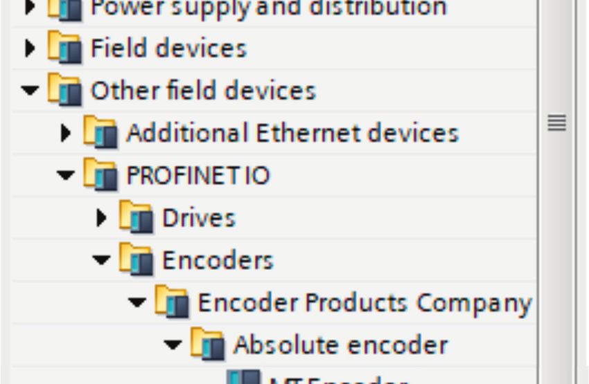
3.3 Principles of EPC’s A58E-series encoders
The following sections describe the basic functions of an absolute encoder.
Unlike incremental encoders, absolute-value encoders output their position value as a digital number via a fieldbus. A distinction
is made here between single turn and multi-turn encoders.
In addition to simply outputting the position value, most encoders permit a certain degree of parameterization, such as selecting
the positive direction of rotation, setting the position value to a reference value at a fixed physical position, and scaling the
position value to an arbitrary resolution and a limited measuring range. This reduces the required complexity of the control
program as well as the computational burden on the controller.
3.3.1 Single turn – ST
Measurement of the angle from 0° to 360° by means of a shaft represents the minimum functionality of a rotary encoder. The
sensor system is based on optical or magnetic sampling of a measuring graduation on the encoder shaft.
The Model A58SE/HE encoders from EPC feature new magnetic technology, which provides maximum precision and resolution for
a single turn encoder.
3.3.2 Multi-turn – MT
A multi-turn encoder allows the number of revolutions to be recorded. This is achieved via a rotation counter. The Model
A58SE and A58HE encoders include technology, which ensures that the corresponding information is retained, even in a
voltage-free state. This means that buffer batteries and gearboxes, which require a comparatively large installation space and a
correspondingly high degree of maintenance, are no longer needed.
3.3.3 Direction of rotation
The positive direction of rotation can be reversed by a simple two’s complement of the position value (invert every bit and
add “1”).
EPC Technical Reference Manual – Absolute Encoders with PROFINET Interface
1-800-366-5412 | encoder.com | sales@encoder.com PAGE 10 OF 64 © 2023 Encoder Products Company, REV 03/14/2023PROFINET® Interface TECHNICAL REFERENCE MANUAL
3.3.4 Preset
The desired position value can be assigned to the encoder at a specific physical position. This must be within the measuring range
so that the position value is correlated with a physical reference position. For this purpose, the difference between the current
position value and the desired value is calculated. The result is stored in non-volatile memory and added to the position value as
an offset.
3.3.5 Scaling
For the precise matching of the position value with the parameter to be measured in physical terms, adjustments can be carried
out using the scaling parameters. The scalable parameters are “Measuring units per revolution (MUPR)” and “Total measuring
range in measuring units (TMR).”
The scaling parameters “Measuring units per revolution (MUPR)” – increments per revolution – indicates the resolution of the
position value per revolution (also: ST resolution). The value equates to 360°. This means that, if a value of 3600 Cts is parametrized,
the encoder outputs the position in 0.1° increments (see Equation #2).
Equation 1 MUPR = ST = 3600 Cts
Equation 2 Angular steps = Angle of one revolution = 360° = 0.1° / Cts
MUPR 36,000 Cts
The scaling parameter “Total measuring range in measuring units (TMR)” – the maximum total measuring range of the position
value (single turn and multi-turn multiplied) – indicates the total resolution of the encoder. When the position value reaches TMR
-1, it jumps back to 0 and vice versa.
As a rule, the selected TMR parameter should be an integer multiple of the “Measuring units per revolution (MUPR)” (see equation
#4), so that the zero point is always at the same position of the encoder shaft.
Equation 3 TMR = 36,000 Cts
Equation 4 MT = TMR = 36,000 Cts = 10
MUPR 3600 Cts
In exceptional cases, it is suitable that TMR is not an integer multiple of MUPR – for example, in a system in which a gear ratio
ensures that the desired measured variable is moving 10% faster relative to the encoder shaft.
In this case, a setting of MUPR = 3960 Cts and TMR = 36,000 Cts would ensure that the faster (but not directly measurable) shaft
can be measured with a resolution of 0.1° and over a range of 10 revolutions. Normally, the number of revolutions would be
calculated by dividing the position value by MUPR. In this case, however, it must be divided by 3600 Cts, since the result would
otherwise be the number of revolutions of the encoder shaft and not the faster shaft of the system.
EPC Technical Reference Manual – Absolute Encoders with PROFINET Interface
1-800-366-5412 | encoder.com | sales@encoder.com PAGE 11 OF 64 © 2023 Encoder Products Company, REV 03/14/2023PROFINET® Interface TECHNICAL REFERENCE MANUAL
• It should be noted that measurement errors will occur if the result of this formula is a
decimal.
3.4 Connection assignments for PROFINET encoders
3.4.1 Bus cover with 3 x M12x1
The “RNB” code in the order key refers to an encoder with a bus cover. The electrical connection is made at the bus cover via the
2 x M12 plugs and 1 x M12 socket. The connection assignment of the plugs and sockets can be found in Table 3.1.
Female Connector Power Femail Connector
Female Connector Female Connector Female Connector Female Connector Female Connector
Port1 (IN) Port1 (IN) Power
Port1 (IN)
Power
Port2 (OUT) Port2 (OUT) Port1Port2
(IN) (OUT)
Power
M12x1,
M12x1,4-pin, M12x1, M12x1, M12x1,
M12x1, 4-pin,M12x1, M12x1, M12x1,
M12x1,4-pin, M12x1,
Function
Function 4-pin, Function Function
4-pin, Function
4-pin, Function Function
4-pin, 4-pin, Function Function
4-pin, Function 4-pin, Function 4-pin,
D-coded
D-coded D-coded A-coded A-coded
A-coded D-coded D-coded D-coded
D-coded A-coded
Tx+ Tx+ 1 1 Tx+ (+)1 Vcc (+)1 Vcc (+) Vcc 1 Tx+
1 1 Tx+ Tx+
1 Tx+ 1 1 (+) Vcc 1
Rx+ 2 Rx+ n.2c. 2 n. c. Rx+
2 2 Rx+ 2 Rx+ 2 n. c. 2
Rx+ 2 n. c. 2 Rx+ 2
Tx- 3 Tx- GND
3 3 GND Tx-
3 3 Tx- 3 Tx- 3 GND 3
Tx- Rx- 3 4 Rx- n.4c. GND
4 n. c. 3 Rx-
4 4 Rx- Tx-4 Rx- 3 4 n. c. 4
Rx- 4 n. c. 4 Rx- 4
Table 3.1: Pin connection assignment
3.5 LEDs and signaling
Four status LEDs on the bus cover signal the various encoder states and thus support error diagnosis and troubleshooting in the
field (see Table 3.2). The two Link Activity LEDs (L/A) light up or flash green when the encoder is connected to another PROFINET
node (PLC, switch, additional field device...) and data is being exchanged. The STAT LED indicates the status of the fieldbus, the
MOD LED the status of the encoder.
EPC Technical Reference Manual – Absolute Encoders with PROFINET Interface
1-800-366-5412 | encoder.com | sales@encoder.com PAGE 12 OF 64 © 2023 Encoder Products Company, REV 03/14/2023PROFINET® Interface TECHNICAL REFERENCE MANUAL
STAT LED bicolor MOD LED bicolor Meaning Cause
No voltage
No connection;
red solid green solid Bus disconnection or master not accessible or switched off
no data exchange
Parameterization error,
no data exchange Slave is not configured yet.
Criterion: Incorrect station address, but not out of range.
red flashing green solid Data exchange correct.
However, the slave The actual configuration of the slave differs from the
does not switch to the nominal configuration.
data-exchange mode.
green solid red solid System error Diagnosis exists, slave is in data-exchange mode.
Data exchange, slave
green solid green solid
and operation OK
Table 3.2: LED signals
Explanation of symbols: LED off (no light) / LED on/off (green/red light) / LED flashing (flashing green/red light)
3.6 MAC address and IP address
EPC PROFINET encoders have three MAC addresses. These always start with D4-90-E0-xx-xx-xx. The number depends on the
number of ports on the integrated three-port switch. There is one MAC address each for Port1 and Port2, as well as one MAC
address for the “internal port” to which the encoder itself is connected.
In the delivered state, the PROFINET encoder has no IP address and no name. These are defined during configuration (e.g., TIA Portal).
EPC Technical Reference Manual – Absolute Encoders with PROFINET Interface
1-800-366-5412 | encoder.com | sales@encoder.com PAGE 13 OF 64 © 2023 Encoder Products Company, REV 03/14/2023PROFINET® Interface TECHNICAL REFERENCE MANUAL
4. PROFINET
4.1 Summary of functions
Our PROFINET encoders support the functions shown in Table 4.1, below.
Functions Meaning
Conformance class CC-C
Profile Encoder Profile V4.1
Profile class Encoder Profile Class 4, as well as compatibility with Class 3
Performance Cycle time 250 μs (with clock synchronization) and fast start-up of 1 s
Redundancy MPR and MRPD
Web server Display and configuration parameters, firmware updates
Clock synchronization RT, IRT, and IRT isochronous
Table 4.1: Functions
4.2 GSDML modules
The modules from the current GSDML file are listed in Table 4.2, below.
Designation Meaning
ST0016 No multi-turn, single turn 16 bit
MT4316 Multi-turn 43 bit + single turn 16 bit = 59 bits in total
Table 4.2: GSDML modules
4.3 Signals
Table 4.3, below, shows the signals that are supported by EPC PROFINET encoders.
Signal Description Name Length (bits) Signed
6 Velocity A NIST_A 16 Y
8 Velocity B NIST_B 32 Y
9 Sensor 1 control word G1_STW 16 –
10 Sensor 1 status word G1_ZSW 16 –
11 Sensor 1 position 1 G1_XIST1 32 N
EPC Technical Reference Manual – Absolute Encoders with PROFINET Interface
1-800-366-5412 | encoder.com | sales@encoder.com PAGE 14 OF 64 © 2023 Encoder Products Company, REV 03/14/2023PROFINET® Interface TECHNICAL REFERENCE MANUAL
Signal Description Name Length (bits) Signed
12 Sensor 1 position 2 G1_XIST2 32 N
39 Sensor 1 position 3 G1_XIST3 64 N
80 Encoder control word 2 STW2_ENC 16 –
81 Encoder status word 2 ZSW2_ENC 16 –
238
Sensor position preset control word G1_XIST_PRESET_A 32 N
(60000)
TBD Sensor position preset control word G1_XIST_PRESET_B1 32 N
TBD Sensor position preset control word G1_XIST_PRESET_C 64 N
60001 Debug control word DEBUG_STW 16 N
60002 Debug status word DEBUG_ZSW 16 N
Table 4.3: Signals
4.4 Structure of the signals
NIST_A: Velocity value A
This value includes the velocity, has a width of 16 bits and is signed.
Signal NIST_A
Bits 15 ... 0
Contents
Right-aligned, output in set unit
15 ... 0 Velocity value A
(see Table 4.20, Velocity Measuring Units
Table 4.4: Structure of signal 6 NIST_A
NIST_B: Velocity value B
This value includes the velocity, has a width of 32 bits and is signed.
Signal NIST_B
Bits 31 ... 0
Contents
Right-aligned, output in set unit
31 ... 0 Velocity value B
(see Table 4.20, Velocity Measuring Units
Table 4.5: Structure of signal 6 NIST_B
EPC Technical Reference Manual – Absolute Encoders with PROFINET Interface
1-800-366-5412 | encoder.com | sales@encoder.com PAGE 15 OF 64 © 2023 Encoder Products Company, REV 03/14/2023PROFINET® Interface TECHNICAL REFERENCE MANUAL
G1_STW: Sensor 1 control word
Signal G1_STW
Bits 15 14 13 12 11 10 ... 0
Contents
0 = Sensor error not confirmed by controller
15 Confirm sensor error
1 = Sensor error confirmed by controller
0 = Normal operation
14 Park mode
1 = Activate park mode
0 = Do not interrogate
13 Cyclically query absolute position value
1 = Master performs query (cyclic output of G1_XIST2)
0 = Preset not active
12 Activate preset
1 = Preset active
0 = Set preset to absolute value
11 Preset mode
1 = Move preset by value (offset)
10 ... 0 Reserved, currently not used
Table 4.6: Structure of signal 9 G1_STW
• To enable the encoder to respond to the requirements in G1_STW, the controller
must set bit 10 to 1 in STW2_ENC.
G1_ZSW: Sensor 1 status word
Signal G1_ZSW
Bits 15 14 13 12 11 10 ... 0
Contents
Signals a sensor error and outputs a device-specific error code
15 Sensor error
in G1_XIST2
14 Park mode active Confirms "Park mode.” No error messages are transmitted
13 Cyclically query absolute position value Confirms "cyclically query absolute position value"
12 Preset activated Confirms "activate preset"
EPC Technical Reference Manual – Absolute Encoders with PROFINET Interface
1-800-366-5412 | encoder.com | sales@encoder.com PAGE 16 OF 64 © 2023 Encoder Products Company, REV 03/14/2023PROFINET® Interface TECHNICAL REFERENCE MANUAL
Signal G1_ZSW
Signals processing of the requested sensor error
11 Sensor error acknowledgement active
acknowledgement
10 ... 0 Reserved, currently not used
Table 4.7: Structure of signal 10 G1_ZSW
G1_XIST1: Sensor 1 position 1
Signal G1_XIST1
Bits 31 ... 0
Contents
31 ... 0 Absolute position value 1 Right-aligned
Table 4.8: Structure of signal 11 G1_XIST1
Structure of G1_XIST1 using the example of a 16-bit multi-turn and a 16-bit single turn encoder:
31 30 29 28 27 26 25 24 23 22 21 20 19 18 17 16
M M M M M M M M M M M M M M M M
15 14 13 12 11 10 9 8 7 6 5 4 3 2 1 0
S S S S S S S S S S S S S S S S
M = multi-turn / S = single turn
This value includes the position, has a width of 32 bits, and is unsigned. The encoder parameter settings influence this position
value if “Class 4 functionality” is activated. The influence of the preset functionality can be controlled with “G1_XIST1 Preset
Control.”
G1_XIST2: Sensor 1 position 2
Signal G1_XIST2
Bits 31 ... 0
Contents
31 ... 0 Absolute position value 2 Right-aligned
Table 4.9: Structure of signal 12 G1_XIST2
EPC Technical Reference Manual – Absolute Encoders with PROFINET Interface
1-800-366-5412 | encoder.com | sales@encoder.com PAGE 17 OF 64 © 2023 Encoder Products Company, REV 03/14/2023PROFINET® Interface TECHNICAL REFERENCE MANUAL
This value includes the position, has a width of 32 bits and is unsigned. The encoder parameter settings influence this position
value if “Class 4 functionality” is activated. When activated, the preset functionality always has an influence on G1_XIST2.
• If an error occurs, G1_XIST2 contains the error register instead of the position value.
G1_XIST3: Sensor 1 position 3
Signal G1_XIST3
Bits 63 ... 0
Contents
63 ... 0 Absolute position value 3 Right-aligned
Table 4.10: Structure of signal 39 G1_XIST3
This value includes the position, has a width of 64 bits and is unsigned.
It can be used if the measuring range of the encoder is larger than 32 bits. The encoder parameter settings influence this position
value if “Class 4 functionality” is activated.
STW2_ENC: Encoder control word 2
Signal STW2_ENC
Bits 15 ... 12 11 10 9 ... 0
Contents
Receives a count value from 1 to 15 when
15 ... 12 Sign-of-life from the PLC
isochronous transmission is activated
11 Reserved, currently not used
0 = No control by PLC
10 Control by PLC
1 = Control by PLC
9 ... 1 Reserved, currently not used
Controls the execution of the preset
0
1 = Preset executed
Table 4.11: Structure of signal 80 STW2_ENC
EPC Technical Reference Manual – Absolute Encoders with PROFINET Interface
1-800-366-5412 | encoder.com | sales@encoder.com PAGE 18 OF 64 © 2023 Encoder Products Company, REV 03/14/2023PROFINET® Interface TECHNICAL REFERENCE MANUAL
ZSW2_ENC: Encoder status word 2
Signal STW2_ENC
Bits 15 ... 12 11 ... 10 9 8 ... 0
Contents
Sends a count value of 1 to 15 when the
15 ... 12 Sign-of-life from the encoder isochronous transmission is activated and a
sign-of-life has been received from the PLC
11 ... 10 Reserved, currently not used
0 = No control by PLC
9 Control by PLC
1 = Control by PLC
9 ... 0 Reserved, currently not used
0 = No fault
3 Fault present
1 = Fault present
0 = Velocity not valid
2 NIST_VALID
1 = Velocity valid
0 = Position value not valid
1 XIST_VALID
1 = Position value valid
0 Preset Acknowledge Confirms the execution of the preset
Table 4.12: Structure of signal 81 ZSW2_ENC
G1_XIST1_PRESET_B: Sensor position preset control word
Signal G1_XIST1_PRESET_B
Bits 31 30 ... 0
Contents
Controls the transmission of the preset value
31 Trigger bit
1 = Run preset
30 ... 0 Preset value without sign Includes the 31-bit-wide preset value
Table 4.13: Structure of signal 238(60000) G1_XIST1_PRESET_B
EPC Technical Reference Manual – Absolute Encoders with PROFINET Interface
1-800-366-5412 | encoder.com | sales@encoder.com PAGE 19 OF 64 © 2023 Encoder Products Company, REV 03/14/2023PROFINET® Interface TECHNICAL REFERENCE MANUAL
• This signal is intended to ensure compatibility with Siemens products. As an
alternative to 238, this signal can be assigned the number 60000.
G1_XIST1_PRESET_B1: Sensor position preset control word
Signal G1_XIST1_PRESET_B1
Bits 31 ... 0
Contents
31 ... 0 Preset value without sign Includes the 32-bit-wide preset value
Table 4.14: Structure of signal G1_XIST1_PRESET_B1
G1_XIST1_PRESET_C: Sensor position preset control word
Signal G1_XIST1_PRESET_C
Bits 63 62 ... 0
Contents
Controls the transmission of the preset value
63 Trigger bit
1 = Run preset
62 ... 0 Preset value without sign Includes the 63-bit-wide preset value
Table 4.15: Structure of signal G1_XIST1_PRESET_C
DEBUG_STW: Debug control word
Signal DEBUG_STW
Bits 15 ... 1 0
Contents
15 ... 1 0 Not used
0 Set test error Triggers the test error when set to “0”
Table 4.16: Structure of signal 60001 DEBUG_STW
EPC Technical Reference Manual – Absolute Encoders with PROFINET Interface
1-800-366-5412 | encoder.com | sales@encoder.com PAGE 20 OF 64 © 2023 Encoder Products Company, REV 03/14/2023PROFINET® Interface TECHNICAL REFERENCE MANUAL
DEBUG_ZSW: Debug status word
Signal DEBUG_ZSW
Bits 15 ... 1 0
Contents
15 ... 1 0 Not used
0 Test error active Indicates that the test error is set
Table 4.17: Structure of signal 60002 DEBUG_ZSW
4.5 Telegrams
The supported standard telegrams and manufacturer-specific telegrams are described in Table 4.18, below.
• For telegram 860, the manufacturer signal 238 (alternatively 60000) is used.
• For telegram 59000, the manufacturer signals 60001 and 60002 are used.
Data Word
Nr. Dir.
1 2 3 4 5 6 7 8 9 10
SPS -> ENC STW2_ENC G1_STW
81
ENC -> SPS ZSW2_ENC G1_ZSW G1_XIST1 G1_XIST2
SPS -> ENC STW2_ENC G1_STW
82
ENC -> SPS ZSW2_ENC G1_ZSW G1_XIST1 G1_XIST2 NIST_A
SPS -> ENC STW2_ENC G1_STW
83
ENC -> SPS ZSW2_ENC G1_ZSW G1_XIST1 G1_XIST2 NIST_B
SPS -> ENC STW2_ENC G1_STW
84
ENC -> SPS ZSW2_ENC G1_ZSW G1_XIST3 G1_XIST2 NIST_B
SPS -> ENC G1_XIST_PRESET_A
86
ENC -> SPS G1_XIST1 NIST_B
DEBUG_
SPS -> ENC STW2_ENC G1_STW
STW
59000
DEBUG_
ENC -> SPS ZSW2_ENC G1_ZSW G1_XIST1 G1_XIST2
ZSW
Table 4.18: Telegrams
EPC Technical Reference Manual – Absolute Encoders with PROFINET Interface
1-800-366-5412 | encoder.com | sales@encoder.com PAGE 21 OF 64 © 2023 Encoder Products Company, REV 03/14/2023PROFINET® Interface TECHNICAL REFERENCE MANUAL
4.6 Parameters
PNU Sub-Index Bits Function
65000 Preset value
0 Code sequence
1 Class 4 functionality
2 G1_XIST1 preset control
1
3 Scaling function control
4 Alarm channel control
5 Compatibility mode
2 Faults
65001 3 Supported faults
4 Warnings
5 Supported warnings
6 Encoder profile version
8 offset value
9 Measuring units per revolution
10 Total measuring range in measuring units
11 Velocity measuring unit
65002 Preset value 64 bit
1 offset value 64 bit
65003 2 Measuring units per revolution 64 bit
3 Total measuring range in measuring units 64 bit
EPC Technical Reference Manual – Absolute Encoders with PROFINET Interface
1-800-366-5412 | encoder.com | sales@encoder.com PAGE 22 OF 64 © 2023 Encoder Products Company, REV 03/14/2023PROFINET® Interface TECHNICAL REFERENCE MANUAL
PNU Sub-Index Bits Function
922 Telegram selection
925 Number of controller sign-of-life failures which may be tolerated
964 Device identification
965 Encoder profile number
970 Load parameter set
971 Transfer to non-volatile memory
972 Encoder reset
974 Base mode parameter access service identification
975 Encoder object identification
976 Load device parameter set
977 Transfer in non-volatile memory (global)
978 List of all DO-IDs
979 Sensor format
980...989 Number list of defined parameter
2000 Hysteresis position
2002 Extrapolation position
2003 Filter max. RPM
2004 Filter position
2005 Filter speed
Table 4.19: Supported parameters
4.6.1 Description of the most important parameters
4.6.1.1 Code sequence
Defines the counting direction of the position value in relation to the encoder shaft.
“0” means a positive counting direction of the position value with clockwise rotation of the shaft; “1” means a positive counting
direction with counter-clockwise rotation.
4.6.1.2 Class 4 functionality
Switches the scaling, preset, and code sequence functionality on and off. When switched on, the position values G1_XIST1, G1_
XIST2 and G1_XIST3 are influenced by the scaling and the code sequence, and G1_XIST2 and G1_XIST3 by the preset. In addition,
if “G1_XIST1 Preset control” is also activated, G1_XIST1 is also affected by the preset, otherwise it is not.
EPC Technical Reference Manual – Absolute Encoders with PROFINET Interface
1-800-366-5412 | encoder.com | sales@encoder.com PAGE 23 OF 64 © 2023 Encoder Products Company, REV 03/14/2023PROFINET® Interface TECHNICAL REFERENCE MANUAL
4.6.1.3 G1_XIST1 preset control
Controls whether a preset command affects G1_XIST1 and is switched on with “0” and off with “1.” Has no function unless “Class
4 Functionality” is activated. Only affects G1_XIST1, i.e. if the preset function is activated and the “G1_XIST2 Preset control” is
switched off, G1_XIST2 is nevertheless affected by the preset.
4.6.1.4 Scaling function control
This parameter turns the scaling functions on and off. If it is not activated, the position values G1_XIST1, G1_XIST2 and G1_XIST3
are not affected. The scaling of the velocity value is PROFIdrive-specific and is not influenced by the position scale. The current
setting can be read by object P65001, sub-index 1, bit 3. To use the scaling functions, “Class 4 functionality” must be activated.
4.6.1.5 Preset value
The preset value is governed by the scaling and can be reset repeatedly and stored in non-volatile memory via P971. By default
has the preset value has the value 0.
Setting a preset value has no effect on the position value for the time being. The preset function is only executed by setting bit 12
in G1_STW.
4.6.1.6 Measuring units per revolution
For encoders, this parameter defines the number of increments required to resolve one 360° rotation of the encoder shaft. This
parameter must be set during parameterization (octets 5...8). The current setting can be read by object P65001, sub-index 9.
4.6.1.7 Total measuring range in measuring units
Defines the entire measuring range of the encoder, i.e. after how many increments the position value resets to 0. For example, if
“Measuring units per revolution” is 100 and “Total measuring range” is 250, the position value will return to 0 after 2.5 revolutions
of the encoder shaft.
4.6.1.8 Velocity measuring units
This parameter defines the unit of the velocity values NIST_A and NIST_B. The following units are possible:
Unit Parameter value
Increments / s 0
Increments / 100 ms 1
Increments / 10 ms 2
Rotations / min 3
Table 4.20: Velocity measuring units
EPC Technical Reference Manual – Absolute Encoders with PROFINET Interface
1-800-366-5412 | encoder.com | sales@encoder.com PAGE 24 OF 64 © 2023 Encoder Products Company, REV 03/14/2023You can also read