LI-210R Photometric Sensor - Instruction Manual - LI-COR Biosciences
←
→
Page content transcription
If your browser does not render page correctly, please read the page content below
LI-210R
Photometric Sensor
Instruction Manual
LI-210R Photometric Sensor
                                            Instruction Manual

LI-COR Biosciences
4647 Superior Street
Lincoln, Nebraska 68504
Phone: +1-402-467-3576
Toll free: 800-447-3576 (U.S. and Canada)
envsales@licor.com

Regional Offices

LI-COR Biosciences GmbH
Siemensstraße 25A
61352 Bad Homburg
Germany
Phone: +49 (0) 6172 17 17 771
envsales-gmbh@licor.com

LI-COR Biosciences UK Ltd.
St. John’s Innovation Centre
Cowley Road
Cambridge
CB4 0WS
United Kingdom
Phone: +44 (0) 1223 422102
envsales-UK@licor.com

LI-COR Distributor Network:
www.licor.com/env/distributors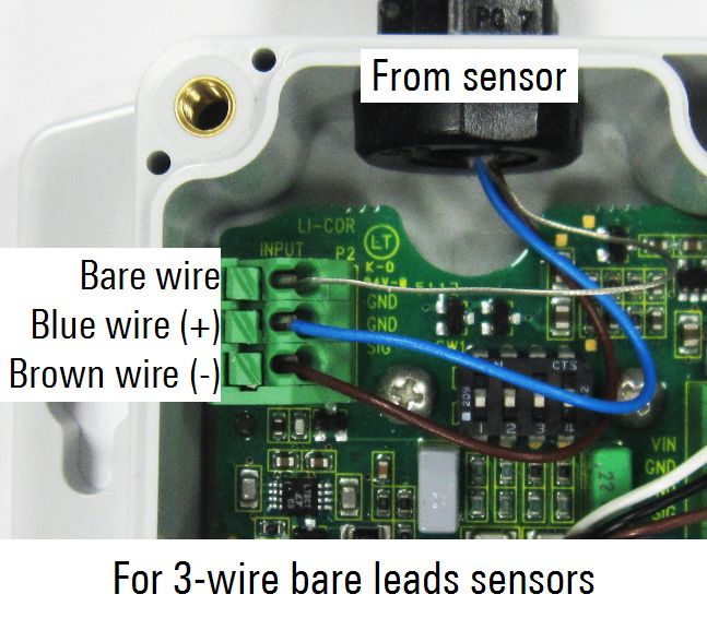
NOTICE
The information contained in this document is subject to change without notice.
LI-COR® MAKES NO WARRANTY OF ANY KIND WITH REGARD TO THIS MATERIAL, INCLUDING, BUT NOT
LIMITED TO THE IMPLIED WARRANTIES OF MERCHANTABILITY AND FITNESS FOR A PARTICULAR
PURPOSE. LI-COR shall not be liable for errors contained herein or for incidental or consequential damages in con-
nection with the furnishing, performance, or use of this material.
This document contains proprietary information which is protected by copyright. All rights are reserved. No part of this
document may be may be reproduced or translated into another language with prior written consent of LI-COR, Inc.
All other trademarks or registered trademarks are property of their respective owners.
© Copyright 2015–2016, LI-COR, Inc.

CE Marking:
This product is a CE-marked product. For conformity information, contact LI-COR Support at envsupport@licor.com. Out-
side of the U.S., contact your local sales office or distributor.
This device complies with part 15 of the FCC Rules. Operation is subject to the following two conditions: (1) This device
may not cause harmful interference, and (2) this device must accept any interference received, including interference that
may cause undesired operation.

Printing History
Publication Number: 984-15209
New editions of this manual will include all updates. An update addendum may be used between editions to provide up-
to-date information. Revisions are indicated by the revision number. Minor updates, which do not alter the meaning of
the content, will be incorporated without affecting the revision number.

 Version         Publication               Changes
 Number          Date
 1               April 2015                First Edition
 2               May 2015                  Second Edition; Edited Troubleshooting section.
 3               July 2015                 Added specifications for operating temperature and relative
                                           humidity range.
 4               November 2015             Removed specification for relative humidity range. Corrected wire
                                           positioning in the photo that shows how to connect a sensor to
                                           the 2420-BL Light Sensor Amplifier.
 5               February 2016             Replaced China RoHS tables for the LI-210R.
 6               February 2017             Added comment on compatiblity of 2420 with data loggers.
Build Date: Tuesday, August 31, 2021

                                                             ii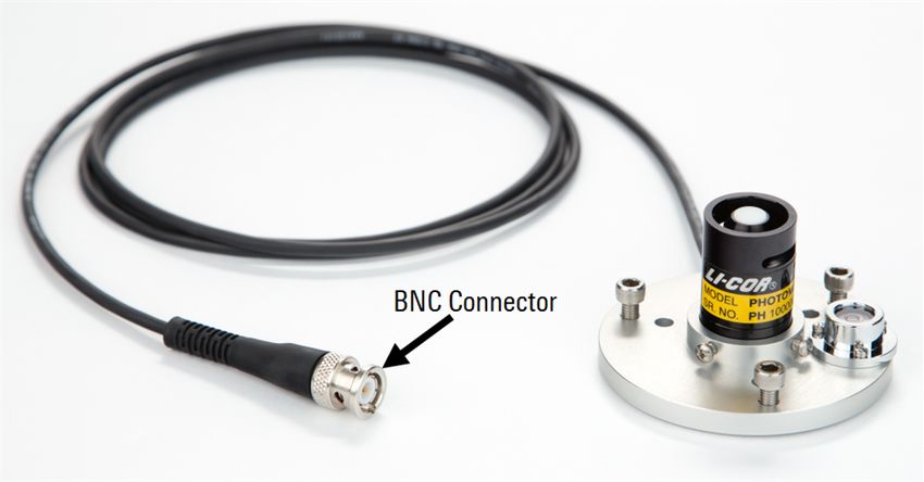
LI-210R-BL-x; LI-210R-BNC-x (x = 2, 5, 15, 50)
                                                             Hazardous Substances or Elements
                                                                       Chromium VI Polybrominated Polybrominated
                                                                       Compounds Biphenyls        Diphenyl Ethers
         Component Name            Lead (Pb) Mercury (Hg) Cadmium (Cd) (Cr6+)      (PBB)          (PBDE)
Photometric Sensor Head Assembly        X           O              X             O                  O                 O
Base and Cable Assembly                 X           O              O             O                  O                 O

O: this component does not contain this hazardous substance above the maximum concentration values in homogeneous
materials specified in the SJ/T 11363-2006 Industry Standard.
X: this component does contain this hazardous substance above the maximum concentration values in homogeneous materials
specified in the SJ/T 11363-2006 Industry Standard (Company can explain the technical reasons for the "X")

                               LI-210R-BL-x; LI-210R-BNC-x (x = 2, 5, 15, 50)

                                        (Pb)        (Hg)           (Cd)              (Cr6+)                 (PBB)   (PBDE)
                                        X           O              X             O                  O                 O
                                        X           O             O              O                  O                 O

O:                                                      SJ/T 11363-2006                             o

X:                                                            SJ/T 11363-2006                               (         ,
                         "X"                            )
 Doc. #53-14983-B December 11, 2015

                                       LI-210R-SMV-x (x = 2, 5, 15, 50)
                                                              Hazardous Substances or Elements
                                                                       Chromium VI Polybrominated Polybrominated
                                                                       Compounds Biphenyls        Diphenyl Ethers
         Component Name            Lead (Pb) Mercury (Hg) Cadmium (Cd) (Cr6+)      (PBB)          (PBDE)
Millivolt Adapter Assembly             X          O            O              O           O              O
Photometric Sensor Head Assembly        X           O              X             O                      O             O
Base and Cable Assembly                 X           O              O             O                      O             O

O: this component does not contain this hazardous substance above the maximum concentration values in homogeneous
materials specified in the SJ/T 11363-2006 Industry Standard.
X: this component does contain this hazardous substance above the maximum concentration values in homogeneous materials
specified in the SJ/T 11363-2006 Industry Standard (Company can explain the technical reasons for the "X")

                                       LI-210R-SMV-x (x = 2, 5, 15, 50)

                                        (Pb)        (Hg)           (Cd)            (Cr6+)                   (PBB)   (PBDE)
                                        X           O              O              O                     O             O
                                        X           O              X             O                      O             O
                                        X           O              O              O                     O             O

O:                                                      SJ/T 11363-2006
X:                                                            SJ/T 11363-2006                               (         ,
                         "X"                            )
 Doc. #53-15082-B December 11, 2015

                                                                                              iii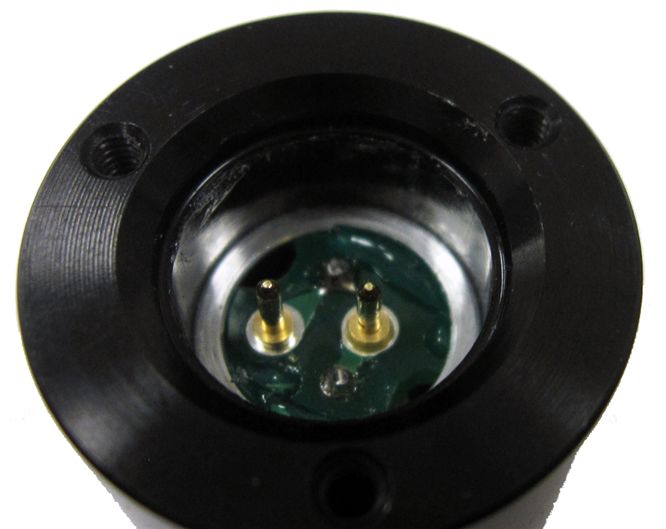
2420-BL
                                                                   Hazardous Substances or Elements
                                                                           Chromium VI Polybrominated Polybrominated
                                                                           Compounds Biphenyls        Diphenyl Ethers
           Component Name              Lead (Pb) Mercury (Hg) Cadmium (Cd) (Cr6+)      (PBB)          (PBDE)
Amplifier Bare Lead Assembly               X          O            O              O           O              O

O: this component does not contain this hazardous substance above the maximum concentration values in homogeneous
materials specified in the SJ/T 11363-2006 Industry Standard.
X: this component does contain this hazardous substance above the maximum concentration values in homogeneous materials
specified in the SJ/T 11363-2006 Industry Standard (Company can explain the technical reasons for the "X")

                                                          2420-BL

                                           (Pb)       (Hg)              (Cd)           (Cr6+)             (PBB)   (PBDE)
                                           X          O                O             O                O             O

O:                                                            SJ/T 11363-2006                         o

X:                                                                 SJ/T 11363-2006                        (         ,
                         "X"                              o

     Doc. #53-14832   March 23, 2015

                                                       2420-BNC
                                                                   Hazardous Substances or Elements
                                                                           Chromium VI Polybrominated Polybrominated
                                                                           Compounds Biphenyls        Diphenyl Ethers
           Component Name              Lead (Pb) Mercury (Hg) Cadmium (Cd) (Cr6+)      (PBB)          (PBDE)
Amplifier BNC Assembly                     X          O            O              O           O              O

O: this component does not contain this hazardous substance above the maximum concentration values in homogeneous
materials specified in the SJ/T 11363-2006 Industry Standard.
X: this component does contain this hazardous substance above the maximum concentration values in homogeneous materials
specified in the SJ/T 11363-2006 Industry Standard (Company can explain the technical reasons for the "X")

                                                       2420-BNC

                                           (Pb)       (Hg)              (Cd)           (Cr6+)             (PBB)   (PBDE)
                                           X          O                O             O                O             O

O:                                                            SJ/T 11363-2006                         o

X:                                                                 SJ/T 11363-2006                        (         ,
                         "X"                              o

 Doc. #53-14833       March 23, 2015

                                                                                                iv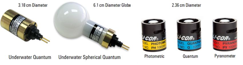
Contents

Section 1. General Information
Comparing LI-COR® Radiation Sensors                                 1-1
Cable Options                                                       1-2
Accessories                                                         1-3
Configurations                                                      1-4

Section 2. Using the LI-210R Photometric Sensor
Mounting                                                            2-1
Calibration Constants and Multipliers                               2-2
    Calibration constant                                            2-2
    Multiplier for use with LI-COR handheld meters and loggers      2-2
    Multiplier for use with LI-210R-BL (3-wire bare leads)          2-2
    Multiplier for use with LI-COR 2290 (604 Ω) Millivolt Adapter   2-2
    Multiplier for use with the SMV Photometric Sensor              2-2
Using the LI-210R-BNC Photometric Sensor                            2-3
Using the LI-210R-BL Photometric Sensor                             2-3
Voltage Signal Options                                              2-4

Section 3. Millivolt Adapters
2290 Millivolt Adapter                                              3-1
LI-210R-SMV Photometric Sensor                                      3-2

Section 4. 2420 Light Sensor Amplifier
2420 Amplifier Gain Settings                                        4-2
Connecting to a Data Logger                                         4-4
    Differential Wiring                                             4-4
    Single-ended Wiring                                             4-5
Connecting to a Sensor                                              4-6
Equation Summary                                                    4-8
    Output Voltage                                                  4-8
    Ideal Gain                                                      4-8
    Voltage Multiplier                                              4-8
2420 Amplifier Performance Characteristics                          4-9

                                                         v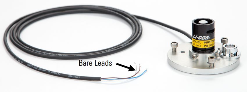
Output                               4-9
    2420 Amplifier Specifications        4-9

Section 5. Performance Characteristics
Cosine Response                          5-1
Spectral Response                        5-3
Calibration                              5-3

Section 6. Care and Maintenance
Factory Recalibration                    6-2
Removing a Cable                         6-2
Sensor Base Cover                        6-3
Installing a Cable                       6-3
Replacement Parts                        6-5

Section 7. Troubleshooting

Appendix A. Specifications

Appendix B. Warranty

Appendix C. Index

                                    vi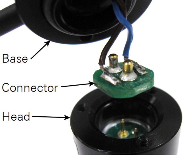
Section 1.
General Information

                  This manual provides basic operating instructions for the
                  LI-210R Photometric Sensor and its accessories. The LI-210R
                  measures visible radiation (light as perceived by the human eye)
                  with a silicon photodiode mounted under a cosine-corrected
                  acrylic diffuser. The sensor output is a current (μA) signal that
                  is directly proportional to hemispherical light. A multiplier is
                  used to convert the current signal into units of radiation (klux).

Comparing LI-COR® Radiation Sensors
                  Each LI-COR radiation sensor is optimized for a particular application and meas-
                  urement type (Table 1-1 below). LI-192SA and LI-193SA sensors are submersible, but
                  they can also be used in the atmosphere. The LI-191R Line Quantum Sensor is often
                  used within plant canopies. LI-190R, LI-200R, and LI-210R sensors consist of a
                  sensor head attached to a removable base and cable assembly.

                  Table 1-1. LI-COR radiation sensors.
                    Sensor                        Measurement              Units       Waveband
                    LI-190R Quantum Sensor        Photosynthetically       μmol s-1    400 to 700 nm
                    LI-191R Line Quantum Sensor   active radiation (PAR)   m-2
                    LI-192SA Underwater
                    Quantum Sensor
                    LI-193SA Underwater
                    Spherical Quantum Sensor
                    LI-200R Pyranometer           Global solar radiation   W m-2       400 to 1100 nm
                    LI-210R Photometric Sensor    Light as perceived by    Lux or      450 to 650 nm
                                                  the human eye            klux

LI-210R Photometric Sensor                                                                              1-1
Section 1. General Information

                   Figure 1-1. LI-COR radiation sensors.

 Cable Options
                   The detachable base and cable assembly provides benefits including:
                     l   Reduced cost of cable repairs
                     l   The ability to replace or recalibrate a light sensor without removing the cable
                         from the mounting structure
                     l   Cable interchangeability with any LI-190R, LI-200R, or LI-210R sensor head

                   Figure 1-2. Sensor base and cable assembly detached from the sensor head.

                   The shielded cable leading from the sensor base terminates with either bare wire
                   leads or a weather-resistant, nickel-plated brass BNC connector (Figure 1-3 on the
                   facing page). For sensors with a BNC connector, the body of the connector carries a
                   positive signal and is connected to the shield of the cable, while the center con-
                   ductor is negative. This arrangement reduces electronic interference.

1-2                                                                                 LI-210R Photometric Sensor
Section 1. General Information
Figure 1-3. Sensor terminals are either a BNC connector or bare leads.
BNC or bare leads (BL) terminal types are available with cable lengths of 2, 5, 15, or
50 meters.
Calibrated LI-190R, LI-200R, or LI-210R sensor heads (without
cables) are available for purchase. Sensor heads can replace
damaged heads, or be used as spares. Any cable assembly can
be used interchangeably with any LI-190R, LI-200R, or LI-210R
sensor head.
Accessories
These optional accessories are available for use with the LI-210R Photometric Sensor:
l 2290 Millivolt Adapter: 604 Ω resistance (Multiplier for use with LI-COR 2290
(604 Ω) Millivolt Adapter on page 2-2)
l 2420 Light Sensor Amplifier (2420 Light Sensor Amplifier on page 4-1)
l 2003S Mounting and Leveling Fixture: Anodized aluminum with stainless
steel leveling screws and a weatherproof spirit level
l 2001S Sensor Base Cover: Anodized aluminum
Accessories 1-3Section 1. General Information
Configurations
The LI-210R Photometric Sensor connects directly to devices that read a current
(µA) sensor signal (Table 1-2 below). Table 1-3 below lists configurations for pro-
ducing a voltage signal.
Table 1-2. Configurations for a current (µA) signal. Ultimate termination is BNC or
bare leads.
Sensor Termination Type... ...connects to...
LI-210R-BNC l LI-1500 Light Sensor Logger
l LI-1400 Datalogger
l LI-250A Light Meter
LI-210R-BL l Terminal block of the LI-1400 Datalogger
l Non-LI-COR devices that read a current (μA)
signal
Table 1-3. Configurations for a voltage signal. Ultimate termination is bare leads.
Sensor ...coupled with... ...connects to...
Termination...
LI-210R-BNC 2290 mV Adapter Devices that read a voltage signal
(0 to 10 mV output) with good resolution (in the µV
LI-210R-SMV Includes a standardized mV adapter range)
with 10 mV output at full scale (part number 2321)
LI-210R-BL Precision resistor
LI-210R-BNC 2420-BNC Amplifier Devices that read a voltage signal
(-2.5 to 5.0 V output)
LI-210R-BL 2420-BL Amplifier
(-2.5 to 5.0 V output)
1-4 LI-210R Photometric SensorSection 2.
Using the LI-210R Photometric Sensor
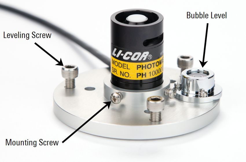
Mounting
The LI-210R Photometric Sensor may be hand-held or mounted to an instrument
platform. For best results, install your sensor in the 2003S Mounting and Leveling
Fixture. Secure the sensor in the fixture by tightening the mounting screws against
the sensor base. Level the fixture with the bubble by adjusting the three leveling
screws. The 2003S Mounting and Leveling Fixture can be secured to a structure with
bolts or screws placed through the three holes in the fixture.
Figure 2-1. LI-210R Photometric Sensor mounted in the 2003S Mounting and Leveling Fix-
ture.
Secure cables to the instrument platform using cable ties. Be sure there is no strain
on the junction where the cable enters the sensor housing, and use a cable tie at any
sharp bends in the cable.
LI-210R Photometric Sensor 2-1Section 2. Using the LI-210R Photometric Sensor
Calibration Constants and Multipliers
Each LI-COR radiation sensor is shipped with a certificate of calibration. The cer-
tificate is also available at www.licor.com/env/support/. Enter the sensor's serial num-
ber in the calibration search box. The calibration constant and multipliers are listed
on the certificate in the following order:
Calibration constant
The current signal produced by a photometric sensor is related to radiation intensity
with a calibration constant unique to each sensor, expressed in units of µA per 100
klux. The calibration constant is used to compute calibration multipliers.
Multiplier for use with LI-COR handheld meters and loggers
LI-COR handheld meters and loggers convert the current (μA) signal into units of
radiation (klux) by applying this multiplier, expressed in radiation units per current
(klux µA-1). This multiplier is a negative number.
Multiplier for use with LI-210R-BL (3-wire bare leads)
This multiplier is expressed in radiation units per current (klux µA-1) and is a pos-
itive number.
Multiplier for use with LI-COR 2290 (604 Ω) Millivolt Adapter
This multiplier is expressed in radiation units per voltage (klux mV-1) and is a neg-
ative number.
Multiplier for use with the SMV Photometric Sensor
The final multiplier listed is -10.0 klux mV-1. The multiplier is the same for any LI-
210R-SMV Photometric Sensor because the resistance of the included standard out-
put millivolt adapter (part number 2321) is adjusted to each sensor's current output
(Voltage Signal Options on page 2-4). The LI-210R-SMV replaces the LI-210SL and
uses the same millivolt adapter and multiplier.
2-2 LI-210R Photometric SensorSection 2. Using the LI-210R Photometric Sensor
Using the LI-210R-BNC Photometric Sensor
Connect the BNC-type cable directly to a BNC input port on
an LI-250A Light Meter, LI-1400 Datalogger, or LI-1500 Light
Sensor Logger. These devices directly measure the current (μA)
signal from the sensor. Enter the sensor's multiplier (see Mul-
tiplier for use with LI-COR handheld meters and loggers on the pre-
vious page) into the device to determine visible light expressed
in units of klux.
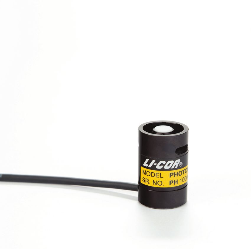
Figure 2-2. LI-210R-BNC Photometric Sensor.
Using the LI-210R-BL Photometric Sensor
Figure 2-3. LI-210R-BL Photometric Sensor featuring 3-wire bare leads.
A BL-type sensor cable terminates with bare wire leads. Connect the bare leads to
the input terminal block of a device that directly measures a current (μA) signal. The
blue wire carries a positive signal and the brown wire is negative. Connecting the
bare (shield) wire to ground will reduce noise in the sensor signal.
Using the LI-210R-BNC Photometric Sensor 2-3Section 2. Using the LI-210R Photometric Sensor
To log radiation units (klux), configure the recording device to multiply the μA sig-
nal by the sensor's multiplier (see Multiplier for use with LI-210R-BL (3-wire bare leads)
on page 2-2) prior to logging the values. If logging the μA sensor signal, apply the
multiplier after logging.
The LI-210R-BL can be used with recording devices that require a voltage (mV) sig-
nal by adding a precision resistor (see Voltage Signal Options below).
Voltage Signal Options
If the meter or logging device requires a voltage signal, options include:
l LI-210R-BNC coupled with a 2290 Millivolt Adapter. The 2290 Millivolt
Adapter converts the current (µA) signal from the sensor into a millivolt-level
voltage (Multiplier for use with LI-COR 2290 (604 Ω) Millivolt Adapter on
page 2-2).
l LI-210R-SMV Photometric Sensor. The LI-210R-SMV includes a Standardized
Millivolt Adapter (part number 2321) matched to a particular sensor. The serial
numbers on the adapter and the sensor must match! The advantage over the
2290 Millivolt Adapter is that the multiplier in your device does not need to be
changed for different sensors (Millivolt Adapters on page 3-1).
l LI-210R coupled with a 2420 Light Sensor Amplifier. The 2420 Amplifier con-
verts the current (µA) signal from the sensor into a voltage (2420 Light Sensor
Amplifier on page 4-1).
l LI-210R-BL coupled with a precision resistor. Connect the resistor across the
positive and negative leads of the cable. The recommended resistance is 604 Ω,
with a maximum output of approximately 10 mV per 100 klux. See Multiplier for
use with LI-COR 2290 (604 Ω) Millivolt Adapter on page 2-2 for instructions on
calculating the multiplier, but use the absolute value of the multiplier.
With a Millivolt Adapter or other resistor, the signal to noise ratio (sensitivity) is
lower than with the 2420 Light Sensor Amplifier, but the cost is less and there is no
need for a power supply to the adapter.
Caution: Do not attach the sensor to a power source. The sensor is self-powered.
2-4 LI-210R Photometric SensorSection 3.
Millivolt Adapters
LI-COR radiation sensors produce a current (μA) output signal that can be con-
verted to a voltage through the use of a resistor. LI-COR makes two types of mil-
livolt adapters for use with our BNC-type radiation sensors. Each adapter includes a
precision resistor and a BNC connector that mates with the sensor. Bare leads can be
connected to a data logger or other device that reads a voltage signal.
The maximum output of LI-COR radiation sensors in typical conditions is relatively
small (microamps of current) and converts into a small voltage. To monitor these
sensors with expected accuracy, a data logger needs to have the ability to measure in
the microvolt range. To increase sensitivity, make sure the voltage range of the chan-
nel is set as close as possible to the full-scale range of the sensor. For example, 0 to
25 mV should cover the range of values expected in a natural sunlight environment.
If the data logger does not have the ability to measure microvolt signals or the abil-
ity to set channel voltage ranges down to a 0–25 mV level, another option should be
considered, such as the 2420 Light Sensor Amplifier.
2290 Millivolt Adapter
An LI-210R Photometric Sensor with a
BNC-type cable can be used with a mil-
livolt recorder or data logger by con-
necting a model 2290 Millivolt Adapter.
Convert the voltage measured by the data
logger into radiation units (klux) by
applying the appropriate multiplier,
given on the sensor's certificate of cal-
LI-210R Photometric Sensor 3-1Section 3. Millivolt Adapters
ibration (see Multiplier for use with LI-COR 2290 (604 Ω) Millivolt Adapter on
page 2-2).
The multiplier M for use with a millivolt adapter can also be found by:
3-1
The 2290 Millivolt Adapter includes a precision resistor with a fixed resistance of
604 Ω, tolerance of ± 0.1%, and a fixed gain of G = 0.604 mV μA-1. The sensor's cal-
ibration constant C is found on the certificate of calibration (see Calibration constant
on page 2-2). The calculated multiplier will be a negative number (because the
shield of the coaxial cable of the sensor carries the positive signal) and is expressed in
units of klux mV-1.
Example: Calculate M using G = 0.604 mV μA-1 and C = 30.56 μA per 100 klux.
3-2
Connecting the 2290 Millivolt Adapter
If the data logger or recorder being used with this millivolt adapter has bipolar cap-
ability, connect the positive (green) lead to the common (low) terminal, and connect
the negative (blue) lead to signal (high) input. This will help minimize noise.
If the data logger has high, low, and ground terminals, place a jumper wire between
the common (low) and ground terminals.
If bipolar signal capability is not available, connect the positive (green) lead to the
signal input, and the negative (blue) lead to the common terminal. In this case, use
the absolute value of the multiplier.
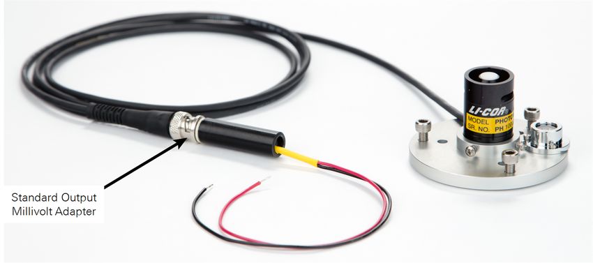
LI-210R-SMV Photometric Sensor
The LI-210R-SMV Photometric Sensor includes a Standard Output Millivolt Adapter
(part number 2321) terminating in bare leads. The serial number on the sensor head
must match the serial number on the adapter because the resistance is adjusted to
each sensor's current output. This allows a standardized output of 10 mV per 100
klux. The multiplier used to convert the voltage measured by the data logger into a
light intensity is -10.0 klux mV-1 (also listed on the sensor's certificate of calibration).
3-2 LI-210R Photometric SensorSection 3. Millivolt Adapters
Figure 3-1. LI-210R-SMV Photometric Sensor.
The advantage of using an LI-210R-SMV (compared to an LI-210R-BNC with a 2290
Millivolt Adapter) is that sensors can be exchanged in the field without the need to
change the multiplier in the data logger or recorder.
An LI-210R Photometric Sensor with a BNC-type connector can be converted to an
LI-210R-SMV by attaching a Standard Output Millivolt Adapter (part number 2321)
to the BNC connector. The 2321 adapter must be matched to the individual sensor.
LI-COR needs the sensor's serial number in order to adjust an adapter to match the
sensor.
Connecting the LI-210R-SMV Photometric Sensor
If your data logger or recorder has bipolar signal capability, connect the positive
(red) lead to the common (low) terminal, and connect the negative (black) lead to
signal (high) input. This will help minimize noise in the signal.
If the data logger has high, low, and ground terminals, place a jumper wire between
the common (low) and ground terminals.
If bipolar signal capability is not available, connect the positive (red) lead to the sig-
nal input, and the negative (black) lead to the common terminal. In this case, use
the absolute value of the multiplier.
LI-210R-SMV Photometric Sensor 3-3Section 3. Millivolt Adapters 3-4 LI-210R Photometric Sensor
Section 4.
2420 Light Sensor Amplifier
                  The 2420 Light Sensor Amplifier converts the current (μA) signal from the radiation
                  sensor into a voltage that can be measured by many data loggers and system con-
                  trollers. The 2420 Amplifier works with both old and new LI-COR radiation sensor
                  designs. Two amplifier models are available:

                    Note: The 2420 Amplifier is weather resistant with the lid properly attached,
                    but if it is to be left outdoors for long periods of time, it should be installed in a
                    protective enclosure or sheltered location.

                    Note: Because indoor light conditions are often very low, you may find that the
                    2420 has insufficient resolution to amplify small light signals, and thus may be
                    incompatible with some data loggers.

LI-210R Photometric Sensor                                                                                   4-1
Section 4. 2420 Light Sensor Amplifier
2420 Amplifier Gain Settings
The 2420 Amplifier provides 15 discrete gain settings to accommodate a variety of
full-scale light intensities, full-scale voltage ranges, and sensor types. This section
shows how to determine the correct gain settings and multiplier. Gather the fol-
lowing information:
l Calibration constant for your light sensor (C)
l Maximum full-scale radiation intensity to be measured (Imax)
l Full-scale input voltage of the datalogger (Vmax)
Follow these steps to calculate the amplifier gain setting and voltage multiplier:
1 Calculate the ideal amplifier gain (Gideal).
Example: Consider a quantum sensor with the following parameters:
l Sensor calibration constant: C = 30.65 μA per 100 klux
l Full-scale light intensity: Imax = 200 klux
l Datalogger full-scale channel voltage: Vmax = 5.0 V
2 Select the gain setting (G) from Table 4-1 on the facing page that is less than or equal to the ideal
gain from step 1.
Example: The ideal gain computed in step 1 is Gideal = 0.0816 V μA-1. On the table,
the closest actual gain that is less than or equal to this value is G = 0.075 V μA-1.
3 Use a number 2 Phillips screwdriver to remove the amplifier lid. Alternate the four screws, pulling
the lid up with the screws as you go so that the screws do not bind with the lid.
4 Using a small screwdriver, set the four switches in the center of the circuit board based on the
amplifier gain determined in step 2.
Example: The amplifier gain determined in step 2 (G = 0.075 V μA-1) requires the
number 1 and 2 switches to be in "off" position, and the number 3 and 4 switches to
be in the "on" position:
G = 0.075
4-2 LI-210R Photometric SensorSection 4. 2420 Light Sensor Amplifier
Table 4-1. Gain settings table for the 2420 Amplifier
2420 Gain Settings Table
DIP Switch Gain (V μA-1) DIP Switch Gain (V μA-1)
G = 0.375 G = 0.175
(all switches off)
G = 0.350 G = 0.150
G = 0.325 G = 0.125
G = 0.300 G = 0.100
G = 0.275 G = 0.075
G = 0.250 G = 0.050
G = 0.225 G = 0.025
G = 0.200 Do Not Use
(all switches on)
5 Re-install the lid. Torque the screws to 0.45 Nm (64 oz-in.) if using a torque screwdriver.
6 Calculate the voltage multiplier (M). The voltage multiplier is used to convert the voltage measured
by the data logger into units of radiation (klux). The units for M are klux V–1.
Example: Calculate M using G = 0.075 V μA-1 from step 2 and C =
30.65 μA per 100 klux from step 1:
2420 Amplifier Gain Settings 4-3Section 4. 2420 Light Sensor Amplifier
Connecting to a Data Logger
Note: The 2420 Amplifier requires a power supply (white wire, +3.8 to 28 VDC),
usually from the datalogger. The datalogger should wait a minimum of 0.12
seconds (120 ms) after providing power before reading the output voltage from
the amplifier.
Figure 4-1. Amplifier Output Terminal Block Wiring
The 2420-BNC and 2420-BL Amplifier output wires (included) can be connected to
a datalogger in both differential and single-ended configurations, as shown in the fol-
lowing diagrams. The differential configuration can give better noise rejection and
lower offset voltages.
Note: Avoid extending the output wire length. The amplifier and data logger
should be kept close together to avoid excess voltage drop and the introduction of
noise.
Differential Wiring
4-4 LI-210R Photometric SensorSection 4. 2420 Light Sensor Amplifier
Single-ended Wiring
Important Note! In the single-ended configuration, use the following steps to
check for ground loops. This procedure only applies when the 2420 is in the
single-ended configuration.
A Disconnect the light sensor from the amplifier.
B Using a multiplier of 1 and an offset of 0 in the datalogger program, monitor the "dark off-
set" mV measurement from the amplifier.
C If the dark offset is > 1 mV, try disconnecting either the brown or black lead (but not both)
to minimize the offset.
D If the offset is minimized by removing either the brown or black wire, then move this wire
off to the side and insulate it with a piece of electrical tape.
E Reconnect the light sensor to the amplifier and reset the multiplier and offset in the data
logger program.
Single-ended Wiring 4-5Section 4. 2420 Light Sensor Amplifier
Connecting to a Sensor
Note: The 2420 Amplifier requires a current (μA) signal from the sensor. It will
not work with a millivolt adapter or with a sensor that produces a voltage signal
output.
LI-COR radiation sensors come wired with bare leads or a BNC connector.
2420-BNC Light Sensor Amplifier: connects to a BNC type light sensor. Attach the
BNC connector to the BNC input port on the Amplifier.
2420-BL Light Sensor Amplifier: connects to a bare lead type sensor with these
steps:
1 Use a number 2 Phillips
screwdriver to remove the
amplifier lid. Alternate the
four screws, moving the lid
up with the screws so that
the screws do not bind
with the lid.
2 Loosen (but do not remove)
the black plastic nut on the
input port.
3 Feed the sensor cable
through the nut and input
port far enough that the black shielded portion extends inside the amplifier, then hand tighten the
nut.
4 Press down the connector’s spring release and insert the sensor wires into the terminal block as
shown below.
4-6 LI-210R Photometric SensorSection 4. 2420 Light Sensor Amplifier
5 Re-install the lid. Torque the screws to 0.45 Nm (64 oz-in.) if using a torque screwdriver.
Connecting to a Sensor 4-7Section 4. 2420 Light Sensor Amplifier
Equation Summary
Output Voltage
The 2420 Light Sensor Amplifier output voltage is computed as:
Variable Units Description
Vout V Amplifier output voltage
G V μA-1 Amplifier gain setting
i μA Light sensor photocurrent signal
Ideal Gain
The ideal gain (Gideal ) is the gain needed by the 2420 Amplifier to adjust the full-
scale sensor output to the full-scale input voltage of the data logger. The 2420 Ampli-
fier uses 15 discrete gain settings, so the ideal gain must be rounded down to the
nearest supported gain. Ideal gain is computed as:
Variable Units Description
Gideal V μA-1 Ideal amplifier gain
Vmax V Data logger full-scale input voltage
Imax klux Photometric sensor full-scale light
C μA per 100 klux Photometric sensor calibration coefficient
Voltage Multiplier
The voltage multiplier M converts the voltage measured by the data logger into a
light intensity. The multiplier is found by:
Variable Units Description
M klux V-1 Photometric sensor voltage multiplier
G V μA-1 Amplifier gain setting
C μA per 100 klux Photometric sensor calibration coefficient
4-8 LI-210R Photometric SensorSection 4. 2420 Light Sensor Amplifier
2420 Amplifier Performance Characteristics
Output
The 2420 Amplifier generates an output signal up to 5.0 V and down to -2.5 V over
the entire input supply voltage range (+ 3.8 to 28 VDC). The output is linear with
the current signal provided by the light sensor with an offset of ± < 10 μV, meaning
that 0 μA of input current yields a 0 V ± < 10 μV output voltage.
Note: The 2420 Amplifier is capable of driving a resistive load of 10 kΩ or greater.
Most datalogger voltage inputs have an input impedance (resistance) much higher
than 10 kΩ, satisfying the output loading requirements of the 2420. Loading the
output with a resistance less than 10 kΩ may cause erroneous readings.
2420 Amplifier Specifications
2420 Light Sensor Amplifier Specifications
Power Requirements: +3.8 to 28 V (1 mA over full range)
Operating Temperature -40 °C to 50 °C
Range:
Turn-on Time: 120 ms
Amplifier Output: -2.5 to 5.0 V
Output Offset Voltage: -10 to 10 μV
Amplifier Gain Range: 0.025 to 0.375 V μA-1
Amplifier Gain Accuracy: ± 0.1% typical (± 0.15% max) of gain setting
Amplifier Output Noise: 0.5 μV rms (0.375 V μA-1 Gain, 0.1 to 10 Hz Bandwidth)
Amplifier Output Loading: ≥ 10 kΩ
2420 Amplifier Performance Characteristics 4-9Section 4. 2420 Light Sensor Amplifier 4-10 LI-210R Photometric Sensor
Section 5.
Performance Characteristics
                  The amount of radiation incident on a given flat (not necessarily level) surface area
                  varies with the angle of incidence. Lambert's cosine law says that the radiant intens-
                  ity observed from an ideal diffusely reflecting surface is directly proportional to the
                  cosine of the angle of incidence.
                  When radiation strikes a given surface area at a greater angle of incidence, less radi-
                  ation is received on that surface (see Figure 5-2 on the next page). For instance, when
                  radiation strikes a given unit area at a 60° angle of incidence, half as much is
                  received compared to a 0° angle of incidence. The same amount of radiation is
                  spread over more surface area at a 60° angle of incidence.

Cosine Response
                  A cosine-corrected sensor follows Lambert's cosine law and provides the most accur-
                  ate measurements of radiation on a flat surface from all angles. Cosine correction
                  ensures accurate measurements under various conditions such as low light levels and
                  low solar elevation angles.
                  The LI-210R is fully cosine-corrected, with sensitivity to light nearly equal at all
                  angles of incidence to about 82° angle of incidence (Figure 5-1 on the next page).
                  Errors are typically less than ± 5% for angles less than 82° from the normal axis. At
                  90°, a perfect cosine response would be zero, and any error at that angle is infinite.

LI-210R Photometric Sensor                                                                             5-1
Section 5. Performance Characteristics
120
Normalized Response (%)
110
100
90
80
0 15 30 45 60 75 90
Angle of Incidence (Degrees)
Figure 5-1. Typical cosine response of the LI-210R Photometric Sensor.
Figure 5-2. LI-COR sensor creating the proper cosine response at various angles of incidence.
5-2 LI-210R Photometric SensorSection 5. Performance Characteristics
Figure 5-2 shows how the design of the sensor creates the proper cosine response.
Radiation is received by an acrylic disc called a diffuser, or eye. When radiation
strikes with a greater angle of incidence, more is received by the edge of the eye.
This compensates for increasing reflection from top surface as the angle of incidence
grows larger. Beyond an angle of about 80°, the rim of the sensor begins to block
some light in order to maintain the correct response as more radiation is received by
the edge of the eye. At a 90° angle of incidence, the rim completely blocks the eye,
in keeping with a proper cosine response.
Spectral Response
The spectral response of a typical LI-210R Photometric Sensor corresponds closely to
the C.I.E. standard observer curve. LI-COR has had sensor calibration data verified
by the National Research Council of Canada (NRC), one of the major standards
laboratories in the world.
1.0
0.75
Relative Response
0.50
0.25
0.0
400 500 600 700
Wavelength (nm)
Figure 5-3. Typical spectral response of the LI-210R Photometric Sensor.
Calibration
Each LI-COR radiation sensor is fully calibrated at the factory, and no user cal-
ibration is needed. Acquire the calibration for your sensor by entering the serial
Spectral Response 5-3Section 5. Performance Characteristics
number at www.licor.com/env/support/. The recommended recalibration interval is
every 2 years. Return your sensor to LI-COR for recalibration (see Factory Recal-
ibration on page 6-2).
Each LI-210R Photometric Sensor is calibrated against a standard lamp using 683
lumens per watt as the value of spectral luminous efficacy at a wavelength of 555
nm. This value conforms to the recommendations of the International Committee
for Weights and Measures (CIPM). The uncertainty of calibration is ± 5%, traceable
to the U.S. National Institute of Standards and Technology (NIST).
5-4 LI-210R Photometric SensorSection 6.
Care and Maintenance
For best performance and longevity, treat the sensor carefully. The protective cap
that came with the sensor can be used later when shipping the sensor for factory
recalibration.
Figure 6-1. LI-210R Photometric Sensor
The vertical edge of the acrylic diffuser (see Figure 6-1 above) must be clean to main-
tain calibration and correct cosine response. Use warm water and a soft, lint-free
towel or cotton-tipped swab to remove dust and other soluble deposits. If needed,
use a mild detergent to clean the sensor. Use a solution of vinegar and water for stub-
born hard water deposits or salt buildup.
Important Note! Refrain from applying pressure to the diffuser when cleaning
the sensor. Scratches on the surface of the diffuser will degrade the cosine per-
formance of the sensor.
The sensor head may be disconnected from the sensor base (Using the LI-210R Pho-
tometric Sensor on page 2-1), but do not attempt to disassemble the sensor head.
Doing so will alter the sensor's calibration, void the sensor's warranty, and poten-
tially provide entry points for water, which will damage the sensor.
LI-210R Photometric Sensor 6-1Section 6. Care and Maintenance
Factory Recalibration
Each sensor is fully calibrated at the factory. The recommended recalibration inter-
val is every 2 years.
Note: A sensor's certificate of calibration indicates the last date of calibration. You
can acquire the certificate of calibration for your sensor by entering the sensor
serial number at www.licor.com/env/support/.
Return your sensor to LI-COR for recalibration. If possible, replace the protective
cap that came with the sensor. Ship the sensor head attached to the base and cable
assembly when possible. For tower installations, solar arrays, or other cases where it
would be better to leave the cable behind, the sensor head may be removed from the
base and cable assembly for shipment (see Removing a Cable below).
For uninterrupted data collection, you have the option of purchasing sensor heads
without cables. These calibrated sensor heads can be used as spares.
Removing a Cable
Figure 6-2. Sensor base and cable assembly with sensor head removed.
1 Remove the sensor from the mounting and leveling fixture to gain access to the machine screws
on the bottom of the sensor base.
2 Remove the three screws from the bottom of the sensor base with a number 1 Phillips screwdriver.
3 Pull the sensor head away from the base until the two-pin female connector separates from the
base pins. Pull the two components straight apart without twisting.
4 If the sensor base will be left exposed, install a Sensor Base Cover (Sensor Base Cover on the
facing page).
6-2 LI-210R Photometric SensorSection 6. Care and Maintenance
Any cable can be used with any sensor head without altering the calibration. Cables
are interchangeable between the LI-190R, LI-200R, and LI-210R sensors.
Sensor Base Cover
When a sensor base must be left behind while the head is being factory re-calibrated,
protect it by attaching a 2001S Sensor Base Cover, available from LI-COR. Attach
using the same screws that held the sensor head to the base.
Figure 6-3. Sensor Base Cover installed on the sensor base in place of the sensor head.
Installing a Cable
1 Place the protective cap (shipped with the sensor) on the sensor head or use another method to
protect the acrylic diffuser on top of the sensor head.
2 Turn the sensor head upside down and check the pins to ensure they are not bent. Inspect the o-
ring in the base and replace if it is damaged.
3 Press the female connector firmly onto the pins of the light sensor head using your finger or a
small flat-blade screwdriver. The two-pin connector is polarized so that it can only be attached in
one orientation.
Sensor Base Cover 6-3Section 6. Care and Maintenance
4 Orient the light sensor and base so the mounting holes align and insert the three machine screws
through the light sensor base and into the sensor head.
5 Tighten the screws with a number 1 Phillips screwdriver. If you are using a torque screwdriver,
tighten the screws to 0.41 Nm (58 oz-in).
6-4 LI-210R Photometric SensorSection 6. Care and Maintenance
Replacement Parts
The following components are available individually.
Base and Cable Assemblies: 210R: Calibrated Photometric Sensor Head
l BNC-2: 2-meter cable with BNC terminal
l BNC-5: 5-meter cable with BNC terminal
l BNC-15: 15-meter cable with BNC terminal
l BNC-50: 50-meter cable with BNC terminal
l BL-2: 2-meter cable with bare leads
l BL-5: 5-meter cable with bare leads
l BL-15: 15-meter cable with bare leads
l BL-50: 50-meter cable with bare leads
You can replace a damaged cable assembly, or change the cable length and terminal
by purchasing a new cable assembly and installing it onto the sensor head.
Calibrated LI-190R, LI-200R, or LI-210R sensor heads (without
cables) are available for purchase. Sensor heads can replace
damaged heads, or be used as spares. Any cable assembly can
be used interchangeably with any LI-190R, LI-200R, or LI-210R
sensor head.
l Flat head Phillips machine screw, 2-56 threads, 1/2" long,
82° countersink, stainless steel (for securing the sensor base
to the sensor head), LI-COR part number 122-12774. Three screws are required
for each sensor.
l O-ring AS-014 Viton75 (for the sensor base), LI-COR part number 192-14878.
Replacement Parts 6-5Section 6. Care and Maintenance 6-6 LI-210R Photometric Sensor
Section 7.
Troubleshooting
                  Sensor readings are negative (-) or zero:
                    l   Check for proper wiring of the LI-210R-BL (see Using the LI-210R Photometric
                        Sensor on page 2-1), 2220 Millivolt Adapter (Multiplier for use with LI-COR 2290
                        (604 Ω) Millivolt Adapter on page 2-2), or LI-210R-SMV (Multiplier for use with the
                        SMV Photometric Sensor on page 2-2).
                    l   Make sure the proper sign was used on the multiplier entered into the LI-1500,
                        LI-1400, or LI-250A, or other recording device (Calibration Constants and Mul-
                        tipliers on page 2-2). If the number is entered without the negative sign, readings
                        will be zero in the LI-1500 and negative in the LI-1400 and LI-250A.

                  Sensor readings are incorrect:
                    l   Make sure the meter or logger is properly configured, including entering the
                        sensor's correct calibration multiplier. Note that multipliers are different from
                        the calibration constant, and there are different multipliers for use with millivolt
                        adapters (see Calibration Constants and Multipliers on page 2-2).
                    l   Check the sensor's last calibration. Certificates of calibration are available at:
                        www.licor.com/env/support/. Enter the sensor's serial number in the calibration
                        data search box. Certificates include multipliers and the sensor's last calibration
                        date. LI-COR recommends factory recalibration for radiation sensors every two
                        years (Calibration Constants and Multipliers on page 2-2).
                    l   Check for loose cable connections. Moisture on connections can also cause erro-
                        neous readings.
                    l   Check the sensor cable for damage, including nicks, cuts, or sharp bends.
                    l   Contact LI-COR technical support if you are unable to resolve the issue.

LI-210R Photometric Sensor                                                                               7-1
Section 7. Troubleshooting 7-2 LI-210R Photometric Sensor
Appendix A.
Specifications
                  Absolute Calibration: ± 5% traceable to the U.S. National Institute of Standards
                       and Technology (NIST)
                  Sensitivity: Typically 30 μA per 100 klux
                  Linearity: Maximum deviation of 1% up to 100 klux
                  Stability: < ± 2% change over one year
                  Response Time: Less than 1 μs (2 m cable terminated into a 604 Ω load)
                  Temperature Dependence: ± 0.15% per °C maximum
                  Cosine Correction: Cosine corrected up to 82° angle of incidence
                  Azimuth: < ± 1% error over 360° at 45° elevation
                  Tilt: No error induced from orientation
                  Operating Temperature Range: -40 °C to 65 °C
                  Detector: High stability silicon photovoltaic detector (blue enhanced)
                  Sensor Housing: Weatherproof anodized aluminum case with acrylic diffuser and
                       stainless steel hardware; O-ring seal on the sensor base
                  Size: 2.36 cm Diameter x 3.63 cm (0.93" x 1.43")
                  Weight: 24 g head; 60 g base and cable (2 m) with screws
                  Cable Length: 2 m, 5 m, 15 m, 50 m (6.5', 16.4', 49.2', 164')

LI-210R Photometric Sensor                                                                       A-1
Appendix A. Specifications 2420 BL Dimensions 2420 BNC Dimensions A-2 LI-210R Photometric Sensor
Appendix A. Specifications

2003S Mounting and Leveling Fixture Dimensions
                                                            3x Leveling Screws
                                          1.75”
                                                             3x    0.19” Mounting Holes
                                   3.0”

                         Bubble
                          Level

                                                            60°
                                                                                                        0.25” (0.63 cm)
                        Slot for
                                                                                                        0.50” (1.27 cm)
                   Sensor Cable

                                                  3x 120°

Appendix A. Specifications                                                                                         A-3
Appendix A. Specifications A-4 LI-210R Photometric Sensor
Appendix B.
Warranty
                  Each LI-COR, Inc. instrument is warranted by LI-COR, Inc. to be free from defects
                  in material and workmanship; however, LI-COR, Inc.'s sole obligation under this
                  warranty shall be to repair or replace any part of the instrument which LI-COR,
                  Inc.'s examination discloses to have been defective in material or workmanship
                  without charge and only under the following conditions, which are:

               1 The defects are called to the attention of LI-COR, Inc. in Lincoln, Nebraska, in writing within one
                 year after the shipping date of the instrument.
               2 The instrument has not been maintained, repaired or altered by anyone who was not approved by
                 LI-COR, Inc.
               3 The instrument was used in the normal, proper and ordinary manner and has not been abused,
                 altered, misused, neglected, involved in an accident or damaged by act of God or other casualty.
               4 The purchaser, whether it is a DISTRIBUTOR or direct customer of LI-COR or a DISTRIBUTOR'S cus-
                 tomer, packs and ships or delivers the instrument to LI-COR, Inc. at LI-COR Inc.'s factory in Lincoln,
                 Nebraska, U.S.A. within 30 days after LI-COR, Inc. has received written notice of the defect.
                 Unless other arrangements have been made in writing, transportation to LI-COR, Inc. (by air unless
                 otherwise authorized by LI-COR, Inc.) is at customer expense.
               5 No-charge repair parts may be sent at LI-COR, Inc.'s sole discretion to the purchaser for install-
                 ation by purchaser.
               6 LI-COR, Inc.'s liability is limited to repair or replace any part of the instrument without charge if
                 LI-COR, Inc.'s examination disclosed that part to have been defective in material or workmanship.
                  There are no warranties, express or implied, including but not limited to any
                  implied warranty of merchantability of fitness for a particular purpose on
                  underwater cables or on expendables such as batteries, lamps, thermocouples,
                  and calibrations.

LI-210R Photometric Sensor                                                                                         B-1
Appendix B. Warranty
Other than the obligation of LI-COR, Inc. expressly set forth herein, LI-COR,
Inc. disclaims all warranties of merchantability or fitness for a particular pur-
pose. The foregoing constitutes LI-COR, Inc.'s sole obligation and liability with
respect to damages resulting from the use or performance of the instrument
and in no event shall LI-COR, Inc. or its representatives be liable for damages
beyond the price paid for the instrument, or for direct, incidental or con-
sequential damages.
The laws of some locations may not allow the exclusion or limitation on implied
warranties or on incidental or consequential damaged, so the limitations herein may
not apply directly. This warranty gives you specific legal rights, and you may already
have other rights which vary from state to state. All warranties that apply, whether
included by this contract or by law, are limited to the time period of this warranty
which is a twelve-month period commencing from the date the instrument is
shipped to a user who is a customer or eighteen months from the date of shipment
to LI-COR, Inc.'s authorized distributor, whichever is earlier.
This warranty supersedes all warranties for products purchased prior to June 1, 1984,
unless this warranty is later superseded. To the extent not superseded by the terms of
any extended warranty, the terms and conditions of LI-COR’s Warranty still apply.
DISTRIBUTOR or the DISTRIBUTOR's customers may ship the instruments dir-
ectly to LI-COR if they are unable to repair the instrument themselves even though
the DISTRIBUTOR has been approved for making such repairs and has agreed with
the customer to make such repairs as covered by this limited warranty.
Further information concerning this warranty may be obtained by writing or tele-
phoning Warranty manager at LI-COR, Inc.
B-2 LI-210R Photometric SensorAppendix C.
Index
Calibration, 5-3
2 certificate, 2-2
2001S Sensor Base Cover, 6-3
constants, 2-2
2003S Mounting and Leveling Fixture, 2-1
factory, 5-3
2290 Millivolt Adapter, 3-1
multipliers, 2-2, 2-4
2321 Standard Output Millivolt Adapter,
Certificate of Calibration, 2-2
3-2 Cleaning, 6-1
2420 Light Sensor Amplifier, 4-1 Comparing Sensors, 1-1
performance characteristics, 4-9 Configurations
specifications, 4-9 for a current signal, 1-4
for a voltage signal, 1-4
A Cosine Response, 5-1
Accessories, 1-3
Amplifier, 4-1 F
Factory Recalibration, 6-2
B Flying Leads, 1-2, 2-4
Bare Leads, 1-2, 2-4
Base and Cable Assembly, 1-2 G
installing, 6-3 Gain Setings Table, 4-3
removing, 6-2 Gain Settings for the 2420 Amplifier, 4-2
Base Cover, 6-3
BNC connector, 1-2
I
Installing Sensors, 2-1
C Installing the Base and Cable Assembly,
Cable Terminals, 1-2
6-3
Cables, 1-2
installing, 6-3
removing, 6-2
L
securing, 2-1 Leveling Sensors, 2-1
LI-1400 Datalogger, 2-3
Appendix C. Index C-1Appendix C. Index
LI-1500 Light Sensor Logger, 2-3
LI-190R Quantum Sensor, 1-1
Q
Quantum Sensor, 1-1
LI-191R Line Quantum Sensor, 1-1
LI-200R Pyranometer, 1-1
LI-210R-BL Photometric Sensor, 2-3 R
LI-210R-BNC Photometric Sensor, 2-3 Radiation, 1-1
LI-210R-SMV, 3-2 Recalibration, 6-2
LI-210R Photometric Sensor, 1-1 Removing the Base and Cable, 6-2
LI-250A Light Meter, 2-3
Light, 1-1 S
Light Meter, LI-250A, 2-3 Sensor Base Cover, 6-3
Light Sensor Specifications, A-1
base/cable, 1-2 2420 light sensor amplifier, 4-9
specifications, A-1 Spectral Response, 5-3
Light Sensor Amplifier, 4-1 Submersible Quantum Sensors, 1-1
Light Sensors
comparing, 1-1 T
mounting, 2-1 Termination Types, 1-4
spectral response, 5-3
Line Quantum Sensor, 1-1 V
Logger Compatibility, 1-4 Voltage Signal Options, 2-4
Loggers
LI-1500 and LI-1400, 2-3
M
Meter Compatibility, 1-4
Meter, LI-250A, 2-3
Millivolt Adapters, 3-1
2290 Millivolt Adapter, 3-1
2321 Standard Output, 3-2
Mounting and Levelling Fixture, 2-1
Mounting Sensors, 2-1
Multipliers, 2-3
for handheld meters, 2-2
for the 2290 Millivolt Adapter, 2-2
for the LI-210R-SMV, 2-2, 3-2
with 3-wire bare leads, 2-2
P
Photometric Sensor, 1-1
Power Supply for the 2420 Amplifier, 4-4
Pyranometer, 1-1
C-2 LI-210R Photometric SensorLI-COR Biosciences 4647 Superior Street Lincoln, Nebraska 68504 Phone: +1-402-467-3576 Toll free: 800-447-3576 (U.S. and Canada) envsales@licor.com Regional Offices LI-COR Biosciences GmbH Siemensstraße 25A 61352 Bad Homburg Germany Phone: +49 (0) 6172 17 17 771 envsales-gmbh@licor.com LI-COR Biosciences UK Ltd. St. John’s Innovation Centre Cowley Road Cambridge CB4 0WS United Kingdom Phone: +44 (0) 1223 422102 envsales-UK@licor.com LI-COR Distributor Network: www.licor.com/env/distributors 984-15209 • 08/2021
You can also read


