Lightning Sensor Classic - Guide for - Jomitek
←
→
Page content transcription
If your browser does not render page correctly, please read the page content below

www.jomitek.dk

Lightning Sensor Classic
                                   Guide for

                       Design-in,
                      Installation,
                      Maintenance
                                 Lightning sensor classic

                                        July 6th 2021

                              Jomitek ApS – Electrical Engineering
Skovlytoften 22, DK-2840 Holte z Tel. +45 45 46 14 15 z Fax +45 45 46 14 16 z CVR-nr. 20 01 99 72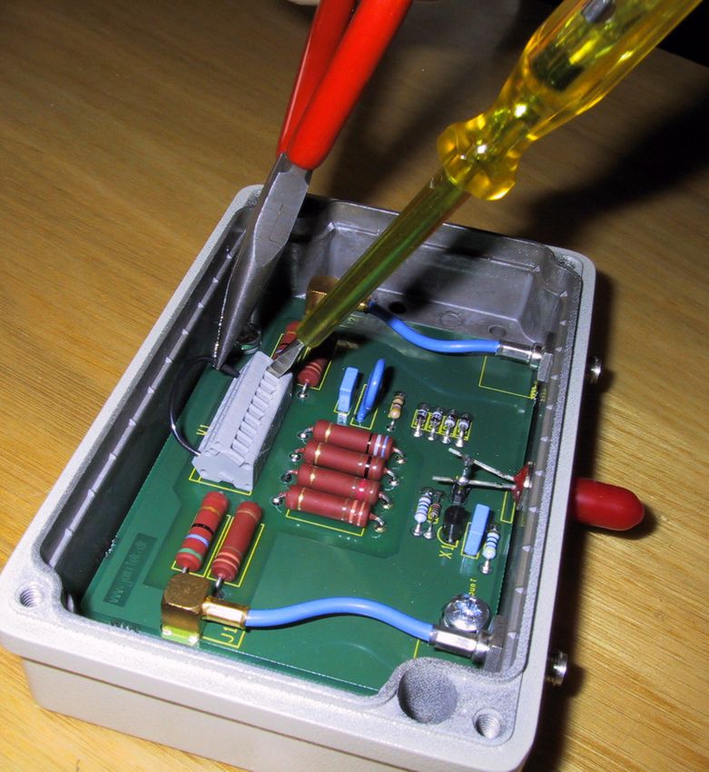
www.jomitek.dk
Content:

Chapter 1 – Design-in:

         1.1       Design-in guidelines
         1.2       Drawings and measures

Chapter 2 – Installation:

         2.1       Who may perform the installation?
         2.2       Tool requirements.
         2.3       Content of a complete sensor.
         2.4       Installation.
         2.5       Test.
         2.6       Relays.
         2.7       Battery maintenance
         2.8       Connections
         2.9       Antenna sensitivity

Chapter 3 – Maintenance:
         3.1       Maintenance

Page 2 of 18
                                             Jomitek ApS – Electrical Engineering
               Skovlytoften 22, DK-2840 Holte z Tel. +45 45 46 14 15 z Fax +45 45 46 14 16 z CVR-nr. 20 01 99 72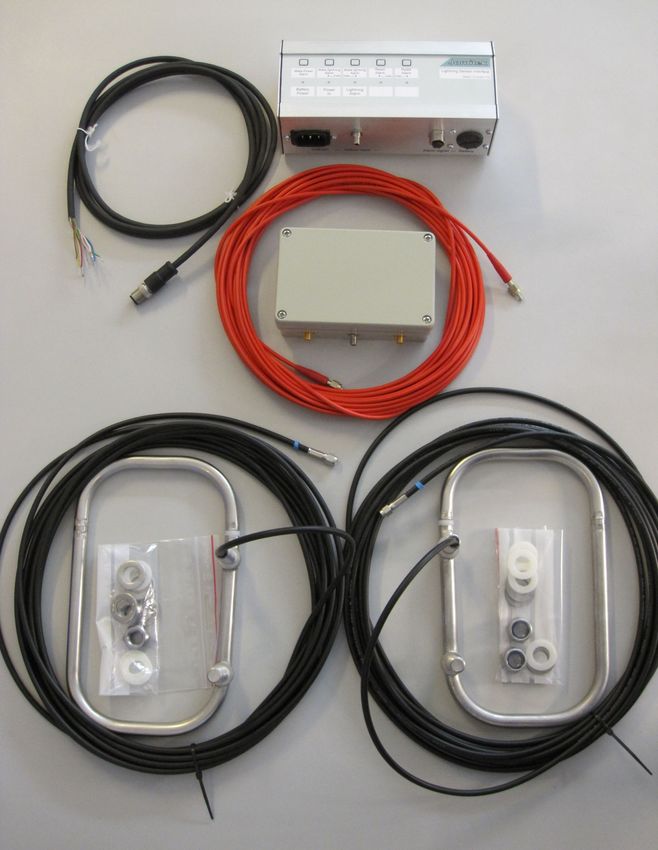
www.jomitek.dk
Chapter 1.
Design-in

1.1     Design-in guidelines
Design engineers can easily include the lightning sensor to all types of wind turbines.

All strikes that hit's a turbine construction will pass the bottom of the tower. The lower 10-15 meters of the
tower is seen as safe installation area (rolling sphere model).

For towers made of concrete material and steel wires, please contact Jomitek for special and free advise.

The 2 antennas has to be placed on opposite sides of the tower. The signal from the two antennas is
summarized in the antenna box. Any strike current that passes inside the tower or through the tower wall
will be measured by the magnetic field generated. By having the antennas 180 degrees from each other,
any strike in nearby turbines will generate a pulse that will have opposite sign in the 2 antennas and
thereby become subtracted and will then not be able to generate an alarm. This gives a design rule of
thumb:

                       1. Place the 2 antennas 180 degrees +/- 5 degrees from each other

The magnetic field generated will form circular field lines around the tower and flow through the
antennas. It is important that these field lines will not become disturbed so the next rule:

 2. Place the antennas at a level where no other iron part will disturb the cirkle +/- 1 meter
                                   in the horizontal plane.

If something big, like a platform structure or a transformer is placed nearby, please ask Jomitek
for an evaluation of the actual placement and disturbances.

To make sure that the magnetic field lines will not induce a damaging high voltage between the
antenna wires and other metal parts the wires should:

        3. Place antenna wires in a horizontal plane +/- 0,5 meters of the antenna level.

As any metallic surrounded hole perpendicular to the current direction will generate a voltage
when strike passes a rule that must apply inside the tower as well as outside the tower is:

  4. Antenna wires must be kept as close to the tower wall as possible and preferable within
                                             10cm

To make sure that the summation of the antenna signals works well it is preferred that

       5. The antenna wires must be approx. the same length for each of the 2 antennas.

Page 3 of 18
                                             Jomitek ApS – Electrical Engineering
               Skovlytoften 22, DK-2840 Holte z Tel. +45 45 46 14 15 z Fax +45 45 46 14 16 z CVR-nr. 20 01 99 72
www.jomitek.dk
As the lightning sensor works on measuring the changing magnetic field :

                     6. It is free to use permanent magnets for mounting any parts.

And finally remember that

                              7. Jomitek always offers free design-in assistance

Page 4 of 18
                                             Jomitek ApS – Electrical Engineering
               Skovlytoften 22, DK-2840 Holte z Tel. +45 45 46 14 15 z Fax +45 45 46 14 16 z CVR-nr. 20 01 99 72
www.jomitek.dk
1.2 Drawings and measures:

Antennas:
The antenna consist of following details:

A.       Antenna frame
B.       Colour label Red=left, Green=right
C.       Nut's and washer's
          2 nuts
          4 steel washers
          4 nylon washers
D.       Antenna wire in specified length
E.       Antennna connector, SMA type

Measures
Height, h                                         225 mm
Width, w                                          135 mm
Distance, d                                       90 mm
Antenna bolts                                      M12
Length bolts                                      40 mm
Max diameter of connector                         9,5 mm

All materials suitable for harsh off-shore use.

Mounting plates available by special request.

Page 5 of 18
                                               Jomitek ApS – Electrical Engineering
                 Skovlytoften 22, DK-2840 Holte z Tel. +45 45 46 14 15 z Fax +45 45 46 14 16 z CVR-nr. 20 01 99 72
www.jomitek.dk
Boxes:

                           Control box                                                          Antenna box

                                     L                     W                      H                  D               E

Antenna box:                       130                     85                     44                113             52

Control box:                       185                     90                     65

The antenna box is fixed in one of 2 ways:
     1. Use 4 pcs M4 self-tapping bolts in the 4 small holes underneath the box
     2. Use 2 pcs M4 bolts mounted from inside the box through the 2 big holes (see picture).

Page 6 of 18
                                             Jomitek ApS – Electrical Engineering
               Skovlytoften 22, DK-2840 Holte z Tel. +45 45 46 14 15 z Fax +45 45 46 14 16 z CVR-nr. 20 01 99 72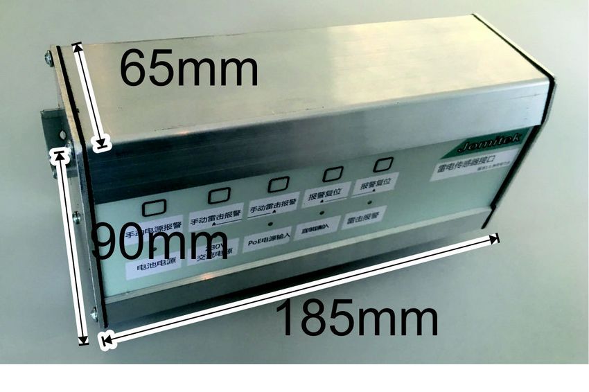
www.jomitek.dk
Chapter 2.
Installation

2.1. Who may perform the installation?

The Lightning Sensor is advanced electronic equipment. The sensor may therefore only be installed by
persons adequately experienced in handling such equipment. In case of need for battery replacement, only
such professional persons may open the box.

2.2. Tool requirements.

1.    Strong drilling equipment
2.    13mm drill
3.    Round file for shaping of the holes
4.    19mm open-ended spanner
5.    Lubricant for stainless steel assembly
6.    Anti oxidations for protection of the drilled holes
7.    Strong aluminium tape or tubes for mounting of the antenna cables
8.    Strips for fixing of vertical cables
9.    Adhesive or bolts for mounting of the antenna box. The box thickness is approx. 3 mm.
10.   Control cable with screening (the connector is included) or it is all included in separate cable kit.

2.3. Content of a complete sensor.

-     2 pcs antennas, including antenna cable
-     1 pcs. antenna box (the small box)
-     1 pcs. optical cable
-     1 pcs. control box (the big box)
-     1 pcs. connector for remote control (or complete cable)
-     1 pcs. IEC cable for AC plug

Page 7 of 18
                                             Jomitek ApS – Electrical Engineering
               Skovlytoften 22, DK-2840 Holte z Tel. +45 45 46 14 15 z Fax +45 45 46 14 16 z CVR-nr. 20 01 99 72
www.jomitek.dk
2.4. Installation.

Only professional and trained personal may install the lightning sensor.

Antennas
1. Find suitable places on the tower (outside) for the 2 antennas. The antennas must be mounted opposite
   each other in the same height above tower button. The exact height of placement is not critical. The
   most important issue is that the antennas must not be damaged by ladder's or persons. As an example,
   the antennas could be placed 1-2 meters above entrance door top level. It is very important, that both
   antennas are mounted having the plastic ring pointing upwards and it is also very important that the
   antennas are placed exactly diagonally across each other.
2.
          The antennas must have the plastic rings at the upward end. See the drawing
                                            below.

3.   Drill 2 holes for each antenna. The 2 holes must be drilled vertically with a centre distance of 90,0mm.
     The drill size is minimum 12 mm, but due to tolerances of the material and the drilling process a hole
     size of 13 mm is recommended.
4.   Remove the burr at the holes with a round file.
5.   Protect the holes against oxidations.
6.   If needed, use 2 thin (fishing line) wires out through the holes. Connect the wires to the antenna legs
     and drag the antennas carefully into position.
7.   Remember to use stainless steel lubricant on the bolts and nuts before assembly. If not used there will
     be a high risk of cold welding of bolt and not assembly. It is recommended to use a maximum torque
     of 35NM due to the nylon washers.
8.   Mount the antenna cable horizontally along the tower wall. You may use aluminium tape (3M) or
     tubes.

Page 8 of 18
                                             Jomitek ApS – Electrical Engineering
               Skovlytoften 22, DK-2840 Holte z Tel. +45 45 46 14 15 z Fax +45 45 46 14 16 z CVR-nr. 20 01 99 72
www.jomitek.dk
Antenna box
9. The antenna box (the small box) must be mounted exactly in the middle between the 2 antennas, inside
    the tower, and in approx. the same height. The connectors must point downwards.
10. Connect the antenna cables. The minimum bending radius is 5cm.
11. Connect the optical cable. Be careful not to bend the optical cable too much during installation. The
    minimum bending radius is 5 cm. Make sure that the cable is fixed so that there is no pull force on the
    optical connector.

Control box
12. The control box may be placed, where it is most appropriate. All connectors should point downwards.
13. Connect the optical cable and the mains IEC cable. Make sure that the mains IEC connector cannot
    drop out due to vibrations.
14. Connect the control cable as shown later in this guide.

Page 9 of 18
                                             Jomitek ApS – Electrical Engineering
               Skovlytoften 22, DK-2840 Holte z Tel. +45 45 46 14 15 z Fax +45 45 46 14 16 z CVR-nr. 20 01 99 72
www.jomitek.dk
2.5. Testing.

If test of the complete system is required after final mounting on the turbine, special test equipment is
needed. Test equipment is not a part of the lightning sensor itself.
Test may only be performed by trained personnel.

1. An electrical field is applied on one of the antennas.
2. Check that the LED for lightning is lit up and that the relay is activated.
3. Reset the lightning signal from the sensor by pressing the 2 front panel buttons at the same time in
   approx. 10 sec. until the diode switches off again and the relay deactivates.
4. Repeat the test using reverse polarity on the antenna.
5. Repeat the above tests on the other antenna
6. Repeat the test with the mains supply switched off during the lightning field pulse on the antennas.

Page 10 of 18
                                              Jomitek ApS – Electrical Engineering
                Skovlytoften 22, DK-2840 Holte z Tel. +45 45 46 14 15 z Fax +45 45 46 14 16 z CVR-nr. 20 01 99 72
www.jomitek.dk
2.6 Relays
From factory the output relays are switched on during normal operation (no lightning).
The reason for configuring the relay output to be on during normal operation, meaning no alarms, is to give
an alarm automatically if the wire is broken or the connector not attached.
This also implies that if the box is dismounted, the turbine control will see this as an alarm situation. A
short circuit at the turbine control input might be needed.
If the battery is not installed or is malfunctioning, the sensor will still work as long as a stable mains supply
is attached.
The output relays are powered by the mains supply, so short interruptions in the mains supply might give
short interruption of the output relays and thereby give short alarm signals. It is recommended that the
turbine control takes care of filtering of such short distortions. Longer interruptions of the mains supply
will give an alarm on the power output relay. Very short interruptions might not give alarms on the power
alarm relay.
When a strike is detected, the red LED is indicating and the alarm relay will open the contact to
signal an alarm.
Page 11 of 18
Jomitek ApS – Electrical Engineering
Skovlytoften 22, DK-2840 Holte z Tel. +45 45 46 14 15 z Fax +45 45 46 14 16 z CVR-nr. 20 01 99 72www.jomitek.dk
2.7 Battery maintenance
The expected lifetime of the battery is 10-20 years. The life time will be shortened dramatically during
days without mains supply. The battery may be exchanged with a corresponding 3,7V Lithium battery, if
the supervision circuit in the sensor signals power failure. Please observe that also errors on the mains
supply will give a power failure signal.
The power failure circuit will not give any alarm if the battery is disconnected.
The battery is NOT connected from factory.
Battery connector
Battery connected
Battery charging
Page 12 of 18
Jomitek ApS – Electrical Engineering
Skovlytoften 22, DK-2840 Holte z Tel. +45 45 46 14 15 z Fax +45 45 46 14 16 z CVR-nr. 20 01 99 72www.jomitek.dk
2.8. Connections
The control-cable must be connected to the control box, using the connector delivered. 2 versions are
available, the older C091 type or the new M12 type.
C091
(Type C 091 D, IEC130-9, and IP67):
Only screened cable may be used for the
control cable.
The connector has to be assembled as follow:
Pin 1 and 2: Power-error relay
Pin 3 and 6: Reset of lightning relay (pin
3 = minus at DC)
Pin 4 and 5: lightning relay
Pin 1. white, pin 2. brown Power failure
Pin 3. green, pin 6. yellow Reset
Pin 4. grey, pin 5. pink Lightning strike
Shield must be connected to the connector housing through the clamp.
Connector seen from soldering side.
Page 13 of 18
Jomitek ApS – Electrical Engineering
Skovlytoften 22, DK-2840 Holte z Tel. +45 45 46 14 15 z Fax +45 45 46 14 16 z CVR-nr. 20 01 99 72www.jomitek.dk
M12
M12 - Version (upgrade from old
C091):
Pin Description
1 Power Failure
2 Power Failure
3 Alarm Reset -
4 Lightning Alarm
5 Lightning Alarm
6 Alarm Reset +
7 Not used
8 Not used
Shield Earth
Jomitek offer ready made cable kits like this:
Page 14 of 18
Jomitek ApS – Electrical Engineering
Skovlytoften 22, DK-2840 Holte z Tel. +45 45 46 14 15 z Fax +45 45 46 14 16 z CVR-nr. 20 01 99 72www.jomitek.dk
Recommendations for Control box cables:
Cable specification signal cable:
LIYCY, 3x2x0,25, twisted pair shielded. Outer diameter approx. 7mm.
Color code according to DIN 47100,
Operating temperature: -30 - +80 degree C
Flame retardant to IEC60332-1
Testing voltage 1200V
Peak operating voltage 300V
Cable specification 230V cable:
Rated voltage 300/500V
H05VV-F 3x0,75
Color coding: brown(Phase), blue(Neutral), yellow/green(Earth)
Operating temperature: -30 - +60 degree C
Free wire ends: 2-3 cm.
Page 15 of 18
Jomitek ApS – Electrical Engineering
Skovlytoften 22, DK-2840 Holte z Tel. +45 45 46 14 15 z Fax +45 45 46 14 16 z CVR-nr. 20 01 99 72www.jomitek.dk
2.9 Antenna sensitivity
The lightning sensor sensitivity may be adjusted into 4 different levels. The factory setting is for level 1,
i.e. maximum sensitivity.
For a turbine having a radius of 2,2 meter at the antennas, the sensitivities are:
Level 1. : 1kA
Level 2.: 2kA
Level 3.: 4kA
Level 4.: 8kA
The sensitivity is dependant of the rise time of the lightning current. See the graph below:
Lynsensor følsomhed
12,0
11,0
10,0
9,0
8,0
7,0
6,0
kA
5,0
4,0
3,0
2,0
1,0
Lightning sensor sensitivity.
Vertically; Lightning current in kA.
Horizontally; Rise time of lightning current in microseconds.
Page 16 of 18
Jomitek ApS – Electrical Engineering
Skovlytoften 22, DK-2840 Holte z Tel. +45 45 46 14 15 z Fax +45 45 46 14 16 z CVR-nr. 20 01 99 72www.jomitek.dk
The sensitivity may be adjusted by placing small wire jumpers into the cage clamp inside the antenna box.
Jumper settings:
Numbering from right to left 1 to 10
Level 1 (1kA): 10-1
Level 2 (2kA): 10-3, 2-1
Level 3 (4kA): 10-7, 6-5, 4-1
Level 4 (8kA): 10-9, 8-7, 6-5, 4-1
Page 17 of 18
Jomitek ApS – Electrical Engineering
Skovlytoften 22, DK-2840 Holte z Tel. +45 45 46 14 15 z Fax +45 45 46 14 16 z CVR-nr. 20 01 99 72www.jomitek.dk
Chapter 3.
3.1 Maintenance
It is recommended that the battery is exchange minimum every 10 years.
The battery is NOT connected from factory.
It strongly recommended to test the installed system one time per year using the system
mentioned in chapter 2.5.
Page 18 of 18
Jomitek ApS – Electrical Engineering
Skovlytoften 22, DK-2840 Holte z Tel. +45 45 46 14 15 z Fax +45 45 46 14 16 z CVR-nr. 20 01 99 72You can also read