Orientation Aid for the Start of the Season - UX01 - AMAZONE ...
←
→
Page content transcription
If your browser does not render page correctly, please read the page content below
Orientation Aid for the Start of the Season
UX01

Service Training

Table of Contents

1.     General information
2.     Start screen of the implement software
3.     Work menu of the implement software
4.     Preparation for operation
5.     Procedure during operation
6.     Software settings
7.     Preparations on the implement - Task Controller

2021 / Status 01                                                   Page 2

Service Training

1. General information
•    Use of this document requires that the operating manuals
     for the implement and the software have been read and
     understood. The corresponding documents are shown on
     the left side.
•    For this reason, it is necessary to take additional
     information from the operating manual. The operating
     manual must always be available when performing the
     orientation aid for the start of the season with the UX 01.
•    The Orientation Aid for the Start of the Season - UX 01
     document serves as a guideline for the user to check the
     implement for the new season and to put it back into
     operation. This document is based on software version
     NW242-F and is also only valid for this version.

2021 / Status 01                                                             Page 3
Service Training

2. Start screen of the implement software
•    The Main menu is divided into the Field menu (1) and the
     Settings menu (2).
•    The menus can be switched by clicking on one of the              1
     marked buttons.
•    From the Field menu, you can switch to the submenus
     Work, Documentation, Filling, Cleaning and Agitation.
     Moreover, it is also possible to enter the desired application
     rate in l/ha here.
•    From the Setting menu, you can switch to the submenus
     Implement, Profile and Info.

                                                                                      2

2021 / Status 01                                                                    Page 4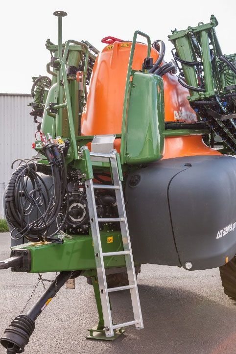
Service Training

3. Work menu of the implement software
                                                     14                  15               20            26               27           33        39   40
                           1

                                                                                          21            28               29           34        41   42
                                                4
            2                                   5
                           7                              16        17
                                                6                                         22            26                30          35
       8

            3              9          10                                                  23                    31             36          37
                                                               18

                12    11                                       19              24                  25           32                         38
                                           13

(1)    Multi-function display, freely configurable
                                                                              (22)   Tilt boom up on one side on the left / right
(2)    Display of the total fill level
                                                                              (23)   Tilt boom down on one side on the left / right
(3)    AutoTrail status
                                                                              (24)   Switch automatic boom guidance on / off
(4)    Application rate from the spray liquid tank
                                                                              (25)   Save spraying height
(5)    Percent value of the application rate
                                                                              (26)   Increase / reduce application rate
(6)    Spray pressure
                                                                              (27)   Switch spraying on / off
(7)    Section Control status
                                                                              (28)   Reset application rate percent value to 100 %
(8)    Part-width section / nozzle status
                                                                              (29)   Switch automatic rate control on / off
(9)    Boom / boom strain status (ContourControl)
                                                                              (30)   Switch on Section Control
(10)   Edge nozzle status
                                                                              (31)   Switch part-width sections off
(11)   Boom illumination status
                                                                              (32)   Switch on the part-width sections
(12)   Pump status
                                                                              (33)   Switch end nozzles off / on
(13)   AmaSelect nozzle body status
                                                                              (34)   Switch boundary nozzles off / on
(14)   Mirror tilt adjustment
                                                                              (35)   Switch extra nozzles off / on
(15)   Lock/unlock boom
                                                                              (36)   AmaSelect automatic or manual nozzle selection
(16)   Fold/unfold boom on both sides
                                                                              (37)   Manually select AmaSelect nozzles
(17)   Boom lifting / lowering
                                                                              (38)   Select band spraying or area spraying
(18)   Tilt boom to right / left
                                                                              (39)   Move AutoTrail to centre position
(19)   Angle boom down/up on both sides
                                                                              (40)   AutoTrail automatic / manual mode
(20)   Fold boom on one side on the left / right
                                                                              (41)   AutoTrail manual steering to the left
(21)   Unfold boom on one side on the left / right
                                                                              (42)   AutoTrail manual steering to the right

2021 / Status 01                                                                                                                                                    Page 5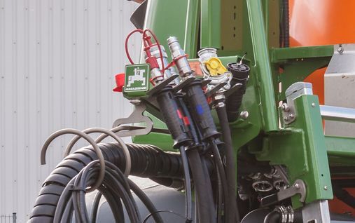
Service Training
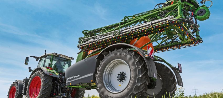
4. Preparation for operation
1
Required tractor equipment
Version Tractor engine power
UX 4201 Starting at 85 kW (115 HP)
UX 5201 Starting at 95 kW (130 HP)
UX 6201 Starting at 110 kW (150 HP)
• Tractor pump capacity:
Profi boom folding 25 l/min
AutoTrail stub axle steering + 10 l/min
ContourControl + 10 l/min
Flushing water pump + 35 l/min
Hydraulic spray pump drive + 50 l/min
• Connections, depending on the implement equipment:
1x pressure-free return flow T, max. 5 bar
1x pressure line P, max. 210 bar
1x load sensing control line (optional)
1x DA jack
• Coupling the implement:
Couple the implement with the towing device of the tractor. Take the hydraulic hoses, universal joint
shaft, supply line for the lighting, brake lines as well as the ISOBUS plug from the parking positions
(1) and couple to the tractor. If a yaw rate sensor is used on the implement side, it is mandatory that
it is connected to the tractor.
2021 / Status 01 Page 6
Service Training

5. Procedure during operation
Filling                                                              2
Suction filling of the spray liquid tank
                                                             3
(1) Run the pump, at least 400 rpm.
(2) Set the suction tap to "Suction via suction
    hose".
(3) Set the pressure tap to "Fill spray liquid tank".
(4) Set the injector switch tap to "Increase filling
    capacity via injector"

                                                                 4
Pressure filling of the spray liquid tank
(optional)

(5) Set the pressure filling switch tap to "Fill spray
    liquid tank".

The position of the other taps on the control panel
are not relevant for pressure filling.                   5

2021 / Status 01                                                                   Page 7
Service Training

5. Procedure during operation
                                                                              1
Induction bowl
The induction bowl can be supplied with water through the suction
connection or the pressure connection (optional) (1).
The following functions can be switched on at the induction                       2   3
                                                                                          4    5
bowl:
1. Spray pistol for cleaning the induction bowl (2)
2. Mixing nozzle for flushing in powders or pellets (3)
3. Canister cleaning (4)
4. Ring line to dissolve and flush in crop protection agents (5)
Supply via the suction connection
1. Start a suction filling of the spray liquid tank (6)
2. Set the pressure tap to the "+" position (7)
3. If necessary, activate the taps on the induction bowl (2-5)
4. To suction the induction bowl empty, set the injector switch tap
   to "Suction from induction bowl" (8)
5. To increase the pressure on the induction bowl, e.g. for
                                                                                          6
   canister cleaning, set the pressure tap to "Supply induction
   bowl". Caution! The induction bowl is not suctioned empty in
   the process (9)                                                        7
Supply via the pressure connection
1. Start the pressure filling                                             9
2. Pressure filling supply (1)
3. Pressure tap in the "+" position (7)
4. Run the pump
5. Suction the induction bowl empty (8)
6. For more pressure, e.g. for canister cleaning, stop the            8
   pressure filling

2021 / Status 01                                                                                        Page 8
Service Training
5. Procedure during operation
After the sprayer has been filled and
the crop protection products have
been flushing in, the pressure tap
must be switched to "Spraying" (1).
Agitation 1
The valve chest is used to infinitely
variably adjust the agitating intensity on
the control panel: main agitator (2),
secondary agitator (3).
3
2
2021 / Status 01 Page 9Service Training
3
5. Procedure during operation 1
Put the implement into working position 4
2
In the boom kinematics function group, you will find all of the softkeys for moving the boom into working
position.
(1) Lift the boom. 7 5
(2) Unfold the boom to the desired working width.
(3) When the boom is completely unfolded, the boom can be unlocked.
(4) Move the boom to the desired spraying height.
(5) Save the spraying height. *
(6) Switch on the automatic boom guidance. The boom must be completely unfolded 8
and unlocked! *
(7) Switch AutoTrail to automatic mode. **
9
* Only with the optional DistanceControl or ContourControl boom guidance
** Optional
Spraying
1. Per default, the automatic rate control is activated (11). On the right of the spray liquid tank,
information on the application is shown, see page 5 (8).
2. Switch on the main part-width section switch (10).
3. Switch on Section Control (12). To be able to activate this function, the following conditions must be met:
10
• Section Control of the terminal (Task Controller) activated
• Implement error free
• Booms in working position 11
Depending on the setting, the softkey (12) may not be visible in the Implement menu, but may rather appear
in the GPS view. You can find more information about the settings for Section Control in the operating 12
manual for the implement software and the terminal.
4. You can see the status of Section Control based on the symbol (9):
• Grey X: Section Control is not active on the implement and on the terminal
• Symbol flashing in colour: Section Control is active on the terminal, but not on the implement
• Symbol not flashing in colour: Section Control is active on the implement and on the terminal
2021 / Status 01 Page 10Service Training
5. Procedure during operation
Manual cleaning 1
If the implement is equipped with a manually operated valve 5
chest, follow these steps to perform a quick cleaning.
1. Run the pump.
6
2. Make sure that the pressure tap is set to the "Spraying"
position (1).
3. Move the suction tap to the "Suction from the flushing water 2
tank" position (2).
3
4. Open the agitator (3). 4
5. After 10 % of the flushing water supply has been used up,
close the agitator (4).
6. Move the pressure tap to the "Cleaning" position (5).
7. After another 10 % of the flushing water supply has been
used up, close the cleaning (5).
8. Move the suction tap to the "Suction from the spray liquid 7 8
tank" position (6).
9. Move the pressure tap to the "Spraying" position (1).
10.Spray out cleaning water until air emerges from the nozzles.
In the process, switch the part-width sections (7) on and off
several times, and also the edge nozzles if equipped (8).
For intensive cleaning, repeat the steps 1 to 10 for a total of
three times. 10
11.Drain the final residual quantity (9). 9
12.Clean the suction filter and pressure filter (10).
2021 / Status 01 Page 11Service Training
6. Software settings
• (1) Configuring the part-width sections: 1
Settings menu > Profile > Part-width
section control. Here, each part-width
section can be configured.
• (2) Headland pressure: Setting menu >
Profile > Rate control. Here, the desired
headland pressure can be set.
• (3) Start-up ramp: Settings menu >
Profile > Rate control. Here, the "start-up
ramp" can be configured. After switching 2 3
on the sprayer, an increased quantity will
be metered for the entered start-up time /
until the entered start-up speed is
reached.
• (4) Configuring the working height and
headland height: Setting menu > Profile
> Boom behaviour. The working height
can be set in cm and the headland height
in steps: off, low, medium, heigh, and
maximum. 4
2021 / Status 01 Page 12Service Training
6. Software settings 1
AmaSelect / CurveControl
(1) In the Settings>Profile>AmaSelect>Nozzle body menu, the
assignment of the standard nozzle body must be entered.
(2) For each existing nozzle, the nozzle size, the pressure
range, and the working height is entered. The pressure
range must be individually set for automatic switching Nozzle combination
2
Condition
between the nozzles or nozzle combinations. The set the
switching behaviour, the nozzle combination to be used must 1+2 Nozzle 1 < Nozzle 2
first be considered. Then the right sequence for the nozzle 3+4 Nozzle 4 < Nozzle 3
sizes must be observed.
3+4+2 Nozzle 4 < Nozzle 3 <
(3) In the Settings>Profile>AmaSelect>Automatic functions Nozzle 2
menu, the nozzle combination must then be selected.
3
CurveControl
(4) The CurveControl special equipment must be configured in
the Settings>Profile>AmaSelect>Automatic functions menu.
A choice can be made between three metering functions:
Under-metering
Normal metering
Over-metering 4
2021 / Status 01 Page 13Service Training
6. Software settings
AmaSelect Row 3 3
AmaSelect Row can be configured in the
Settings/Profile/AmaSelect/AmaSelect Row menu.
(1) The nozzle assignment must be configured in the
Settings/Profile/AmaSelect/Nozzle bodies menu. In
addition, the nozzle for band spraying must be selected.
For 50 cm row spacing: without 25 cm nozzle expansion,
any nozzle can be selected, with the 25 cm nozzle
expansion, nozzles 3 or 4 must be selected.
For 75 cm row spacing, the 25 cm nozzle expansion must
be installed. Nozzles 1 and 2 must be selected.
(2) Selection of the row spacing: 50 cm or 75 cm (only with
3
25 cm displacement set). When 75 cm row spacing is
selected, a selection can be made between treatment on
the row (on the plant) or treatment between the rows
(nozzles over the plants remain closed). Moreover, the
nozzles in the tramline can be deactivated here.
(3) On the following pages, you can configure:
• Entry of the theoretical spraying height
• Entry of the nozzle angle, depending on the utilised
nozzle
• This is used to calculate the theoretical band width
2021 / Status 01 Page 14Service Training 6. Software settings Steering 1 • In the Settings>Profile>Steering menu, the behaviour of the steering system can be adjusted. (1) Distance from the tractor's rear axle to the coupling point: the value must be measured and set depending on the tractor. (2) Steering point delay: with the steering point delay, the moment for driving into the curve can be adjusted. This value or effect is best detected while steering. The behaviour should be checked and adjusted when driving in a 90° curve at the usual forward speed. Ridge planting (5) must be deactivated. The higher the value, the 2 later the implement is steered. A correctly adjusted implement does not "jerk" (3) Track correction dimension: when the steering point delay (2) is correct, the when steering into the curve and precisely track correction dimension must be set. The track correction dimension can be follows the rear wheel track! directly measured on the track. This value can be best observed from the crest to 1. If the sprayer is steered too late, the steering approx. the beginning of the last third of the curve. PLEASE NOTE! In doing so, point delay should be reduced. the steering axle may not move all the way to the stop. Otherwise, the track 2. If the sprayer is steered too early, the correction dimension cannot be directly measured. steering point delay should be increased. (4) Type of slope counter-steering: manual or automatic. On side slopes, the steering system is manually or automatically overridden to correct the tracking of the sprayer. (5) Ridge planting: for row crops, an increase of the steering angle can be set so that the implement is steered in a larger curve. Ridge curve amplification: the ridge curve amplification parameter describes the amplification of the over-steering. The higher the value, the more the axle is deflected. 3 2021 / Status 01 Page 15
Service Training
6. Software settings
ContourControl / DistanceControl
• In the Settings/Profile/Boom behaviour menu, the following entries are possible:
(1) Working height: if the automatic boom guidance is activated, the boom
(nozzles) will be regulated at this height when spraying.
(2) Lifting the boom at the headlands: off, low (50 cm), medium (100 cm), high 1
(150 cm) or maximum.
(3) Mode (only with Flex-folding 2, Profi-folding 2 or ContourControl): tilting or 2
angling 3
(4) Distance sensors can be deactivated with ContourControl if necessary. With
DistanceControl, this is achieved by unplugging the sensors. This can be 4
necessary, for example, with a reduced working width, if a sensor is looking
onto a tramline or in case of failure of one of the sensors.
3
Tilt mode
Angle-up mode
2021 / Status 01 Page 16Service Training
7. Preparations on the implement - Task Controller
• Terminal: the functions of the Task 1 2
Controller are controlled via the terminal.
The terminal must be prepared accordingly.
You can find more information in the
operating manual for the respective
terminal.
• (1,2) Switch-on and -off time: Settings
menu > Profile > ISOBUS. These times
define the delay between the moment
when the terminal issues the command to
switch the part-width sections on or off and 3
when the implement really executed this
command. Incorrect settings can cause
overlaps or gaps.
• (3) Task Controller: Setting menu > Profile
> ISOBUS. Under the Documentation
point, there is the choice between
"Implement internal" and "Task Controller".
• (4,5) Application maps / jobs: the "TC"
icon on the Work menu and Field menu 4 5
indicates that the implement is receiving
the target application rates from the Task
Controller (application map or job).
2021 / Status 01 Page 17SmartLearning app Info Portal
The AMAZONE SmartLearning app offers Our Info Portal provides a wide variety of
video training courses for the operation of documents for viewing and downloading at
Amazone implements. The video training no charge. These can be technical and
courses can be downloaded onto your promotional printed material as an
smartphone if necessary, and are therefore electronic version or also videos, Internet
available offline. Simply select the desired links and contact data. Information can be
implement for which you want to watch a obtained by mail and subscriptions to new
video training course. published documents from different
categories are available.
www.info.amazone.de/
AMAZONEN WERKE H. Dreyer GmbH & Co. KG
Postfach 51 ꞏ D-49202 Hasbergen-Gaste
Tel. +49 (0)5405 501-0 ꞏ Fax: +49 (0)5405 501-147
www.amazone.de ꞏ www.amazone.at ꞏ email: amazone@amazone.de MG7202You can also read