Lightweight Cellular Concrete for Geotechnical Applications - GUIDE TO
←
→
Page content transcription
If your browser does not render page correctly, please read the page content below
GUIDE TO

Lightweight Cellular Concrete
for Geotechnical Applications

           JANUARY 2021
About the CP Tech Center                                       While this document may not address all of a project’s
                                                               specific details, it provides information for construction
The mission of the National Concrete Pavement
                                                               professionals and design engineers on the use of LCC
Technology Center (CP Tech Center) at Iowa State
                                                               in geotechnical applications, including common uses,
University is to unite key transportation stakeholders
                                                               conceptual guidance, and design guidelines. The
around the central goal of advancing concrete pavement
                                                               applications presented in this guide have exhibited
technology through research, tech transfer, and
                                                               good long-term performance, providing cost-effective
technology implementation.
                                                               solutions and better and safer designs for projects across
                                                               North America.
About the PCA
The Portland Cement Association (PCA) is a nonprofit           This document includes, as an appendix at the end of
organization founded in 1916 that serves America’s             it, a guide specification covering materials, equipment,
cement manufacturers through policy, research,                 construction inspection, and testing requirements for
education, and market intelligence. PCA members                constructing LCC fills.
represent 91 percent of US cement production
capacity with facilities in all 50 states. PCA promotes        Reference Information for this Guide
safety, sustainability, and innovation in all aspects of       Taylor, S. and G. Halsted. 2021. Guide to Lightweight
construction, fosters continuous improvement in cement         Cellular Concrete for Geotechnical Applications. Portland
manufacturing and distribution, and generally promotes         Cement Association, Washington, DC, and National
economic growth and sound infrastructure investment.           Concrete Pavement Technology Center at Iowa State
                                                               University, Ames, IA.
Disclaimers
                                                               © 2021 Portland Cement Association
Neither Iowa State University nor the Portland Cement
Association nor this document’s authors, editors,
designers, illustrators, distributors, or technical advisors   Front Cover Image Credits
make any representations or warranties, expressed or           Top: Throop Lightweight Fill, used with permission
implied, as to the accuracy of information herein and          Center: Cell-Crete Corporation, used with permission
disclaim liability for any inaccuracies.
                                                               Bottom: Portland Cement Association
This publication is provided solely for the continuing
education of qualified professionals. This publication         For More Information
should only be used by qualified professionals who             For technical assistance regarding cement-based concrete
possess all required licenses, who are competent               paving, contact the Portland Cement Association or the
to evaluate the significance and limitations of the            CP Tech Center:
information provided herein, and who accept total
responsibility for the application of this information.        Greg Halsted, Manager
                                                               Pavements and Geotechnical Markets
Iowa State University does not discriminate on the basis       Portland Cement Association
of race, color, age, ethnicity, religion, national origin,     200 Massachusetts Avenue NW, Suite 200
pregnancy, sexual orientation, gender identity, genetic        Washington, DC 20001
information, sex, marital status, disability, or status as     847-972-9058
a US Veteran. Inquiries regarding nondiscrimination            info@cement.org
policies may be directed to the Office of Equal                https://www.cement.org/
Opportunity, 3410 Beardshear Hall, 515 Morrill Road,
Ames, Iowa 50011, telephone: 515-294-7612, hotline:            Peter Taylor, Director
515-294-1222, email: eooffice@iastate.edu.                     National Concrete Pavement Technology Center
                                                               Iowa State University
About this Guide                                               2711 S. Loop Drive, Suite 4700
                                                               Ames, IA 50010-8664
This document, Guide to Lightweight Cellular Concrete
                                                               515-294-5798
for Geotechnical Applications, provides information on
                                                               cptech@iastate.edu
the materials, properties, design, proper handling, and
                                                               https://cptechcenter.org
applications of lightweight cellular concrete (LCC) for
geotechnical applications.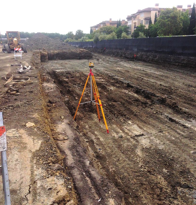
Technical Report Documentation Page

1. Report No.                             2. Government Accession No.           3. Recipient’s Catalog No.
PCA Special Report SR1008P
4. Title and Subtitle                                                           5. Report Date
Guide to Lightweight Cellular Concrete for Geotechnical Applications            January 2021
                                                                                6. Performing Organization Code

7. Author(s)                                                                    8. Performing Organization Report No.
Scott Taylor and Greg Halsted
9. Performing Organization Name and Address                                     10. Work Unit No.
National Concrete Pavement Technology Center
Iowa State University
                                                                                11. Contract or Grant No.
2711 South Loop Drive, Suite 4700
Ames, IA 50010-8664
12. Sponsoring Organization Name and Address                                    13. Type of Report and Period Covered
Portland Cement Association                                                     Guide
200 Massachusetts Avenue NW, Suite 200                                          14. Sponsoring Agency Code
Washington, DC 20001
15. Supplementary Notes
Visit https://cptechcenter.org for color pdfs of this and other publications.
16. Abstract
The primary purpose of this guide is to provide information on the materials, properties, design, proper handling, and applications
of lightweight cellular concrete (LCC) for geotechnical applications.
LCC is a mixture of portland cement and water slurry, combined with preformed foam to create air voids, that can act as a strong,
lightweight, durable, and inexpensive alternative to soil or fill replacement for many geotechnical applications. LCC’s lightweight
property reduces ground settlement and improves the bearing capacity and the static and seismic stability of embankments.
Given that an LCC mix is highly flowable, it can be efficiently and safely placed in confined or problematic spaces such as in pipes,
trenches, tunnels, wall backfills, and other areas where the routine placement of earthen fill is difficult, if not impossible. These
attributes make LCC a low-cost solution for many geotechnical applications.
While this document may not address all of a project’s specific details, it provides information for construction professionals
and design engineers on the use of LCC in geotechnical applications, including common uses, conceptual guidance, and design
guidelines. The applications presented in this guide have exhibited good long-term performance, providing cost-effective solutions
and better and safer designs for projects across North America.
Among other topics, this guide provides examples of both mix design preparation and field installation, geotechnical evaluation,
and the design, construction, and field testing of LCC. Throughout, this guide addresses the importance of geotechnical
oversight at the beginning of a project, during the mix design stage, and during construction to ensure that the project meets its
intended purpose.

17. Key Words                                                                   18. Distribution Statement
geotechnical solutions—LCC design guidelines—LCC geotechnical                   No restrictions.
examples—LCC geotechnical guidance—lightweight cellular concrete
19. Security Classification               20. Security Classification           21. No. of Pages           22. Price
(of this report)                          (of this page)                        58                         NA
Unclassified.                             Unclassified.
Guide to Lightweight Cellular Concrete
for Geotechnical Applications
January 2021

   Authors
   Scott M. Taylor, P.E.
   Greg E. Halsted, P.E., Portland Cement Association

   Managing Editor
   Oksana Gieseman

   Graphic Design, Layout, and Production
   Alicia Hoermann

   Copyeditors
   Sue Stokke and Peter Hunsinger

   Sponsored by
   © 2021 Portland Cement Association

   A guide from
   National Concrete Pavement Technology Center
   Iowa State University
   2711 South Loop Drive, Suite 4700
   Ames, IA 50010-8664
   Phone: 515-294-5798 / Fax: 515-294-0467
   https://cptechcenter.org
iv Guide to Lightweight Cellular Concrete for Geotechnical Applications
Contents
Acknowledgments                                       viii     Chapter 3. Geotechnical Design
Executive Summary                                       1      Considerations                                      20
Chapter 1. Introduction                                 3      Settlement Reduction/Weight Reduction               20
Background of Lightweight Cellular Concrete             3         Net Load Design Method for Settlement Reduction 20
Definition of LCC                                       3      Bearing Capacity                                    22
Scope of This Guide                                     3      Punching Shear                                      23
Benefits                                                3      Buoyancy                                            24
Applications                                            4      Pavement Bases and Subbases                         26
  Lightweight Road Subbases and Fills                   4      Retaining Wall Backfill Soil Pressures              26
  Bridge Approach Embankments                           5      Drainage                                            26
  Void and Cavity Filling                               6      Chapter 4. Mixture Design                           27
  Abandoned Pipe and Culvert Filling                    6      Ingredients                                         27
  Annular Space Grout Filling                           7         Portland Cement                                  27
  Foundation Fills                                      8         Water                                            27
  Energy Arresting Systems                              8         Air                                              28
  Retaining Walls and Precast Wall Panels               8         Foaming Agents                                   28
  Lightweight Dam and Levee Structural Fills            9      Water/Cement Ratio                                  28
  Landslide Repair and Slope Stabilization              9      Mix Design Example (Trial and Error Procedure)      28
  Controlled Density Fill                             10       Laboratory Sample Preparation                       30
Chapter 2. Physical Properties                        11       Chapter 5. Construction                             32
Fresh Properties                                      11       Specifications                                      32
  Cast Density                                        11       Property Requirements                               32
  In-Place Density                                    11       Subgrade and Subbase Preparation                    32
  Oven-Dry Density                                    11       Field Observations                                  33
  Viscosity                                           12       Reinforcement                                       33
  Lateral Fluid Pressure                              12       Transportation                                      33
  Set Time                                            12       Placement and Consolidation                         34
Hardened Properties                                   13       Finishing                                           34
  Hardened Description                                13          Surface Finishes                                 34
  Strength                                            13       Curing and Protection                               35
  Cohesion and Friction Angle                         14       Weather Conditions                                  35
  Modulus of Elasticity                               15       Timing                                              35
  Air Content                                         15       Field Equipment                                     35
  Drying Shrinkage                                    15          Batch Mixing                                     36
  Permeability/Sorption                               16          High-Shear Batching                              36
  Heat of Hydration                                   16          Auger Mixing/Mobile Volumetric Mixers            36
  Thermal Conductivity                                18          Cement Delivery                                  37
  Resistance to Aggressive Environments               19          Ready-Mixed Concrete Plants                      37

                                              Guide to Lightweight Cellular Concrete for Geotechnical Applications    v
Pumping Devices                                           37       References                                 43
     Progressive Cavity Pump                              38       Appendix. Guide Specification for Construction
                                                                    of Lightweight Cellular Concrete Fill       45
     Peristaltic Pump                                     38
     Piston Pump                                          38
Chapter 6. Inspection, Testing, and
Maintenance                                               39
Field Quality Control Testing                             39
Field Quality Control Observation                         40
Post-construction Inspection and Testing                  40
Compressive Strength Testing                              41
Maintenance                                               41

vi          Guide to Lightweight Cellular Concrete for Geotechnical Applications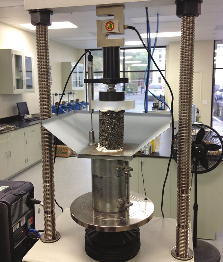
Figures Tables
Figure 1.1. Pavement structure comparison 4 Table 2.1. Physical properties of LCC 13
Figure 1.2. Lightweight road subbases and fills (Ohio) 5 Table 2.2. Friction angles and cohesion values for LCC 14
Figure 1.3. Bridge approach embankments (Indiana) 5 Table 2.3. Modulus of elasticity relationships of LCC 15
Figure 1.4. Void and cavity filling (Alberta) 6 Table 2.4. Summary of cellular concrete hydraulic
conductivity testing 16
Figure 1.5. Pipe and culvert abandonment filling
(Michigan) 6 Table 2.5. Calculated heat capacity and thermal
conductivity of foamed concrete mixes, 300 kg/m3
Figure 1.6. Annular space grout filling (Maine) 7
portland cement content, silica sand fine aggregate 17
Figure 1.7. Ungrouted and grouted annular spaces 7
Table 2.6. Thermal properties of LCC at different
Figure 1.8. Foundation fills (Florida) 8 densities 18
Figure 1.9. Energy arresting systems (West Virginia) 8 Table 4.1. Portland cement types 27
Figure 1.10. Placing LCC backfill behind precast wall Table 4.2. Blended hydraulic cement types 27
panels (California) 9
Table 4.3. Hydraulic cement performance attributes 27
Figure 1.11. Lightweight dam and levee structural fills
(California) 9
Figure 1.12. Landslide repair and slope stabilization
(California) 9
Figure 1.13. Controlled density fill 10
Figure 2.1. Vesicles/air voids 13
Figure 3.1. Net load design method for settlement
reduction 21
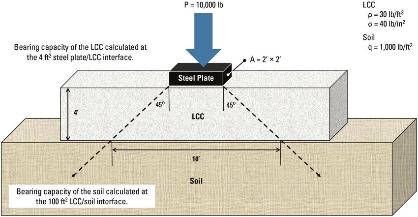
Figure 3.2. Bearing capacity and spread of compressive
forces in LCC 23
Figure 3.3. Punching shear resistance in LCC layer 24
Figure 3.4. Buoyancy considerations in an LCC layer 25
Figure 4.1. Preformed foam generator 31
Figure 5.1. Prepared subgrade awaiting LCC placement 32
Figure 5.2. Welded wire mesh in an LCC placement 33
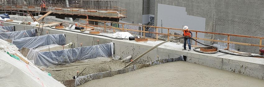
Figure 5.3. How foam is introduced into a ready-mixed
concrete truck-based pumping system 34
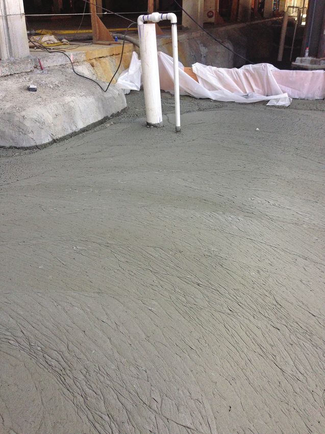
Figure 5.4. Surface of in-place LCC fill 35
Figure 5.5. Batch mixer 36
Figure 5.6. Mobile volumetric mixer 36
Figure 5.7. Inline foam additive system 37
Figure 5.8. Ready-mixed concrete truck 37
Figure 5.9. Progressive cavity pump 38
Figure 6.1. Sampling/testing LCC in the field
(Michigan) 39
Figure 6.2. Surface of recently placed LCC 40
Figure 6.3. Unconfined compressive strength testing of
LCC 41
Guide to Lightweight Cellular Concrete for Geotechnical Applications vii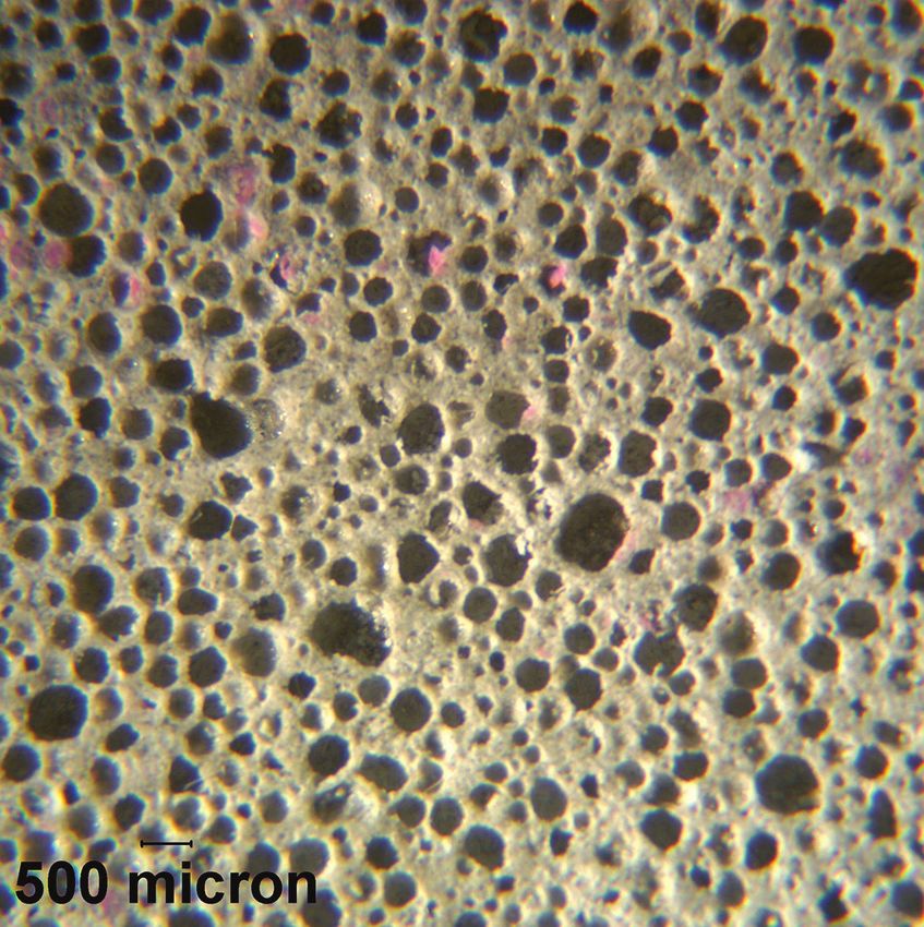
Acknowledgments
The authors, the National Concrete Pavement Technology (CP Tech) Center, and the Portland Cement Association
gratefully acknowledge the contributions of the technical contributors and the technical advisory committee (TAC)
members, who helped establish the technical direction for the guide and reviewed several drafts. Their feedback and
suggestions were invaluable.

• Wayne Adaska, Portland Cement Association                       • James Krstulovich, Illinois Department of Transportation
  (formerly) *
                                                                  • Tarja Kyllönen, Runway Safe Group
• Steven Bartlett, University of Utah *
                                                                  • Roberto Montemayor, University of Illinois at
• Steve Bent, CEMATRIX                                              Urbana-Champaign
• Jacques Bloomfield, The Reinforced Earth Company *              • Gordon Smith, National CP Tech Center *
• Tyler Bodnar, California Nevada Cement Association              • Nico Sutmoller, Aerix Industries
• Tony Borglum, Richway Industries, Ltd.                          • Binod Tiwari, California State University, Fullerton *
• Jesse Downs, Strong Manufacturing                               • Trevor Towery, Elastizell Corporation of America *
• Milton Gomez, Aerix Industries *                                • Diego Villegas, Cell-Crete Corporation
• Ray Henn, RW Henn LLC *                                         • Jeff Wykoff, California Nevada Cement Association
                                                                    (formerly) *
• Craig Hrkal, Cellular Concrete Inc. *
                                                                  * TAC members
• Jon (Ike) Isaacson, Brierley Associates Corporation

viii      Guide to Lightweight Cellular Concrete for Geotechnical Applications
Executive Summary
The primary purpose of this guide is to provide The six chapters in this guide cover the following
information for construction professionals and design information:
engineers on the materials, properties, design, proper
handling, and applications of lightweight cellular concrete • Chapter 1. Introduction
(LCC) for geotechnical applications, including common Chapter 1 covers the scope of the guide, provides a
uses, conceptual guidance, and design guidelines. This definition of and background for LCC, describes the
guide does not cover the properties or uses of LCC for benefits of using LCC for geotechnical applications,
roof deck systems, autoclaved aerated cellular concrete for and lists many of those applications.
creating lightweight precast items, or lightweight structural • Chapter 2. Physical Properties
concrete for reducing the dead loads to concrete elements. Chapter 2 covers both the fresh and hardened
This guide also does not discuss the use of permeable properties of LCC and the importance of these
low-density cellular concrete or cellular concrete having an properties in geotechnical applications.
oven-dry density greater than 50 lb/ft3 (800 kg/m3).
• Chapter 3. Geotechnical Design Considerations
Initially used as a construction product for flooring Chapter 3 covers the important engineering design
systems in both Europe and the United States during principles required for consideration of LCC on
the first part of the 20th century, LCC was eventually geotechnical projects.
granted a patent in 1934. Since then, the commercial
use of LCC has grown into the industry it is today, with • Chapter 4. Mixture Design
many types of applications in a variety of fields. Chapter 4 covers the ingredients of LCC and the
process used to determine the proper cement, water,
LCC is a mixture of portland cement and water slurry, and air content for LCC and includes information on
combined with preformed foam to create air voids, laboratory sample preparation.
that can act as a strong, lightweight, durable, and
inexpensive alternative to soil or fill replacement for many • Chapter 5. Construction
geotechnical applications. Its lightweight property reduces Chapter 5 discusses the requirements and process for
ground settlement and improves the bearing capacity and constructing an LCC fill, the equipment and procedures
the static and seismic stability of embankments. required, and field observations to ensure quality.
Given that an LCC mix is highly flowable, it can be • Chapter 6. Inspection, Testing, and Maintenance
efficiently and safely placed in confined or problematic Chapter 6 provides information on field quality control
spaces such as in pipes, trenches, tunnels, wall backfills, testing and observation, post-construction inspection
and other confined areas where the routine placement of and testing, and maintenance.
earthen fill is difficult, if not impossible. These attributes
make LCC a low-cost solution for many geotechnical The following appendix is included at the end of this guide:
applications. • Appendix. Guide Specification for Construction of
While this document may not address all of a project’s Lightweight Cellular Concrete Fill
specific details, this guide provides examples of both mix The appendix provides a guide specification covering
design preparation and field installation, geotechnical materials, equipment, construction inspection, and
evaluation, and the design, construction, and field testing testing requirements for constructing LCC fills.
of LCC, among other topics. Throughout, this guide
addresses the importance of geotechnical oversight at the
beginning of a project, during the mix design stage, and
during construction to ensure that the project meets its
intended purpose.
Executive Summary 12 Guide to Lightweight Cellular Concrete for Geotechnical Applications
Chapter 1. Introduction
Background of Lightweight Cellular                               Scope of This Guide
Concrete                                                         This guide provides information for construction
Initially used as a construction product for flooring            professionals and design engineers on the materials,
systems in both Europe and the United States during the          properties, design, proper handling, and applications of
first part of the 20th century, lightweight cellular concrete    LCC for geotechnical applications, including common
(LCC) was eventually granted a patent in 1934 (Bayer v.          uses, conceptual guidance, and design guidelines. This
Rice 1934). Since then, the commercial use of LCC has            guide does not cover the properties or uses of LCC for
grown into the industry it is today, with many types of          roof deck systems, autoclaved aerated cellular concrete
applications in a variety of fields.                             for creating lightweight precast items, or lightweight
                                                                 structural concrete for reducing the dead loads to
                                                                 concrete elements. This guide also does not discuss the
Definition of LCC
                                                                 use of permeable low-density cellular concrete or cellular
LCC is a mixture of portland cement and water slurry,            concrete having an oven-dry density greater than 50 lb/ft3
combined with preformed foam to create air voids, that           (800 kg/m3).
can act as a strong, lightweight, durable, and inexpensive
alternative to soil or fill replacement for geotechnical
applications. The American Concrete Institute (ACI)              Benefits
Committee 523, which provides information on                     The four primary benefits of LCC for geotechnical
materials, fabrication, properties, design, and handling of      applications are as follows:
the product, defines this material in its Guide for Cast-in-
                                                                 • Significantly lighter in weight than soil
Place Low-Density Cellular Concrete as follows:
                                                                 • Highly flowable and able to fill spaces of any size or
    Concrete made with hydraulic cement, water, and                shape
    preformed foam to form a hardened material having
                                                                 • Often less expensive than many alternative systems
    an oven-dry density of 50 lb/ft3 (800 kg/m3) or less.
    These mixtures may include aggregate and other               • Can accelerate construction schedules
    material components including, but not limited to,           The lightweight property of LCC reduces ground
    fly ash and chemical admixtures. (ACI 2006)                  settlement and improves the bearing capacity and the
The key is obtaining a homogenous and stable air void or         static and seismic stability of embankments when used
cell structure. The cellular structure is attained essentially   as a lightweight fill placed on top of soft, compressible
by the inclusion of macroscopic voids (air bubbles)              soils. Also, given that an LCC mix is highly flowable
resulting from the mechanical incorporation of air or            (even over long distances), it can be efficiently and safely
other gases.                                                     placed in confined or problematic spaces such as in pipes,
                                                                 trenches, tunnels, wall backfills, and other areas where the
In addition to LCC, many other terms are often used              routine placement of compacted earthen fill is difficult,
to describe this material, including low-density cellular        if not impossible. These attributes make LCC a low-cost
concrete (LDCC), foam concrete, and controlled                   solution for many geotechnical applications.
low-strength material (CLSM) (ACI 2006). To avoid
confusion and be consistent, the term used throughout
this document, unless specifically noted otherwise, is
LCC, as it is the best descriptor for the product, is not
brand specific, and clearly and appropriately identifies
the material.

                                                                                           Chapter 1. Introduction          3
The rapid placement and reasonably fast setting time course at the surface, placed over base and/or subbase
of LCC expedite construction operations. Many other layers (typically crushed stone or stabilized materials),
attributes of LCC provide additional advantages for and underlaid by a compacted earthen subgrade (see
specific challenges, including the following: Figure 1.1).
• Aggregate conservation These pavement systems have proven to work successfully
• Insulation in stable soil and foundation conditions, providing a
pavement that is durable and long-lasting. However,
• Freeze-thaw resistance when the soil and site conditions are less than optimal,
• Self-leveling and consolidating placing a layer of strong, lightweight LCC can strengthen
• Energy dissipation and damping and overcome many of the challenges posed by poor
subgrade materials (soft or expansive clays, collapsible or
• Density, strength, and permeability control reactive soils, etc.). The primary design consideration for
• Ability to be excavated use of LCC in these situations is weight compensation.
• Inert/nonflammable The displacement of soft compressible soil is generally
• Local availability due to excessive loads applied to these soils. LCC can be
• Ease of pumping utilized as a full or partial replacement for the subbase
layer in these applications to produce a zero or low net
• Dynamic properties load increase to the foundation soil.
• Reduced transportation costs and emissions
Geotechnical engineers perform pavement thickness,
• Increased worker safety weight reduction, and embankment stability calculations,
This guide discusses the segments of the geotechnical obtained primarily from laboratory testing, using
marketplace where LCC has been successfully used and representative material properties and unit weights for the
reviews the above properties, functions/advantages, respective materials and soils. These calculations must also
and benefits. The LCC applications presented in this account for possible roadway elevation and groundwater
guide have exhibited excellent long-term performance, changes from seasonal cycles or construction dewatering
providing cost-effective solutions and better and safer in addressing construction and long-term loading
designs for projects across North America. configurations. In this document, this determination of
load balancing of the pavement/embankment system
is referred to as the net load design method and is
Applications further described in Chapter 3. This method is used to
Lightweight Road Subbases and Fills ensure the short- and long-term stability and settlement
Most modern roadways consist of a structural pavement performance of the roadway system.
section comprised of a concrete or asphalt riding/wearing
National CP Tech Center
Figure 1.1. Pavement structure comparison
4 Guide to Lightweight Cellular Concrete for Geotechnical Applicationsupward as it nears the bridge, causing the likelihood of
settlement to increase and warranting a higher factor
of safety (FOS) and greater designed LCC thickness to
resolve the settlement potential. If not addressed during
the design and construction phases, long-term differential
consolidation settlement of the foundation soils can
occur, often creating a bump at the bridge, which is
typically found between the abutment and the approach
slab. This settlement can lead to potential safety hazards
and cause comfort issues for drivers, as well as lead to an
increasing rate of structural deterioration and long-term
© 2002 Elastizell Corporation of America, used with permission
maintenance costs for the roadway.
Figure 1.2. Lightweight road subbases and fills (Ohio)
Estimates show that bridge approach slab problems affect
The benefits of this geotechnical structural solution about 25% of the bridges in the US (Briaud et al. 1997).
for an actively settling roadway begin with its expected A more recent report (2017) from the Federal Highway
long-term performance with little or no settlement. By Administration (FHWA) states that about 9% of the
installing an inert, engineered, lightweight cementitious over 600,000 bridges in the US are structurally deficient.
layer or embankment of material with an unconfined Undoubtedly, many of these bridges are affected by
compressive strength that is up to 5 to 10 times stronger approach settlement, or the bump. Fortunately, when soft
than a typically compacted soil or granular material, the and compressible ground conditions are encountered, the
subbase is both strengthened and reduced in weight. weight reduction function of LCC can resolve the soil
In addition, this practical solution produces a relatively issues, eliminating the bump at the bridge without the
strong, self-consolidating roadway subbase material that need for more costly soil remediation methods.
increases the pavement life and greatly diminishes the
Just like road subbases and fills, another benefit of
potential for significant settlement (see Figure 1.2).
installing LCC for bridge approach embankments is that
Another benefit of installing LCC as opposed to other installation typically takes less time and equipment than
alternatives is that it typically takes less time and alternative solutions, which can result in significant cost
equipment to install, which can result in significant cost and time savings.
and time savings, especially when compared to a solution
Other design and construction considerations when
requiring massive surcharge loadings of embankment
selecting LCC are the width of the embankment and
foundations, which can take many months. Because LCC
whether side slopes for vegetation or retaining walls are
is a highly flowable material that is also self-consolidating
used. Sloping LCC embankments are typically constructed
and self-leveling, it eliminates the need to compact and
with a stepped surface below the finished grade (see Figure
level the subgrade before it is placed. These properties
1.3) and capped with about 2 ft (0.6 m) of soil placed over
reduce the need for extra equipment and labor at a jobsite.
the top to create a vegetative landscape surface.
Lastly, this application of LCC is also environmentally
friendly, in that the imported LCC fills provide 130 yd3
(100 m3) per delivered load of dry cement while soil and
granular fills provide only 10 to 15 yd3 (8 to 11 m3) per
load. The reduced trucking significantly reduces CO2
emissions and traffic congestion, pavement wear, and
noise. It also reduces the use of scarce natural resources.
Bridge Approach Embankments
Bridge approaches are elevated pavement sections coming
up to the edge of a bridge abutment. The corresponding
LCC approach embankments are designed using the net
load design method, often using strict design criteria
and performance requirements. The challenge is that © 1993 Elastizell Corporation of America, used with permission
the typical height of the approach embankment slopes Figure 1.3. Bridge approach embankments (Indiana)
Chapter 1. Introduction 5When designing retaining walls or abutments with LCC
backfill, the lateral loads on the structures are reduced,
allowing for the use of less costly systems. This load
reduction can often lead to significant cost savings on the
walls, foundations, and internal reinforcement.
The use of LCC as an embankment fill has been proven
successful in many situations. Typical projects include
large freight rail grade separation structures constructed
using large volumes of LCC paired with precast concrete
panel systems. On these types of projects, LCC is used as CEMATRIX, used with permission
the “lightweight soil” replacement in the structural and Figure 1.4. Void and cavity filling (Alberta)
geotechnical designs.
Void and Cavity Filling
One of the most common reasons for using LCC is its
highly flowable property. The air bubbles added to the
cement paste act like tiny ball bearings within a void
or cavity, allowing the material to flow rapidly into all
available spaces. Once all water has been removed from
the voids prior to starting, the highly flowable nature
of LCC allows for easy pumping and long-distance
transportation in hoses, which results in easy installation
in difficult locations (see Figure 1.4). © 2017 Elastizell Corporation of America, used with permission
Figure 1.5. Pipe and culvert abandonment filling (Michigan)
Abandoned Pipe and Culvert Filling
Frequently, utility companies, public agencies, and private While many different materials, including sand, CLSM,
owners require upgrades to their network of underground and polyurethane foam, can be used to fill abandoned
pipes. While many pipes are left in place after their pipes, the ability to install the material efficiently is
service lives, requirements by many local agencies state critical. With LCC, most pipes can be pumped from
that these pipes cannot be left empty due to safety and/ one end to the other in a single operation. The ability
or settlement concerns. The solutions are to either pay for LCC to fill a pipe should be evaluated not only
for the pipe to be removed or to fill the decommissioned based on length or absolute volume but also based on
pipe. If filling the pipe is the option selected, LCC can be the time it takes to fill the cavity. A basic approach is
produced onsite and pumped directly into the abandoned that a pipe should not be pumped into for longer than
pipe through installer-provided bulkheads and inlets (see four hours due to cement hydration (cure) time, unless a
Figure 1.5). set retarding admixture is used.
These bulkheads serve to block the highly flowable LCC For instance, with nonrestrictive conditions, a target
material from going the wrong direction and can be made application rate for a typical LCC installer to achieve is
of many products that provide a watertight seal. Once about 100 yd3 (75 m3) per hour. At this rate, the pipe to
all water has been removed from the voids, a 2, 3, or 4 be filled should not exceed 400 yd3 (300 m3). Equipment
in. (50, 75, or 100 mm) injection pipe is placed through sizes and production rates can vary greatly, so this
these bulkheads, through which the LCC is pumped. quantity is not necessarily a requirement or restriction.
The LCC then fills the pipe from one end to the other, Ambient temperatures have an effect, and admixtures and
expelling all the air through the vent pipe(s) located at mix designs may be adjusted to accommodate pumping
the high points. times longer than four hours.
6 Guide to Lightweight Cellular Concrete for Geotechnical ApplicationsOnce the required material properties of the fill are Annular space tunnel grout is a standard LCC installation
determined (typically equivalent to or better than the and is a subset of the pipe fills previously described. The
adjacent soil is sufficient), it is a simple decision between same benefits apply, but the distances are often much
the various types of flowable products. A typical product longer. The purpose of an annular space tunnel grout is to
that is often specified is a flowable fill material or CLSM, fill the open space outside a new pipe that is installed in
which is a one- or two-sack (94 or 188 lb [43 or 85 kg]) a new tunnel or channel. These are typically medium- to
cement and sand and/or fly ash mixture creating a low- large-diameter pipes.
strength concrete product with unconfined compressive
strengths between 50 and 150 lb/in2 (0.34 and 1.03 A special excavation method is used to create a tunnel
MPa). However, these mixes can be extremely difficult with its supporting systems. This method is fine for
to pump. Pumping distances over 200 ft (60 m) often holding the void open but not for containing pressurized
require additional excavations to allow for dividing the fluids. Specified pipes are installed in the opening to
pipe into small enough fill segments. In many instances, transmit the final product (sewage, water, gas, etc.). This
the cost of these additional excavations, backfill, and installation leaves a void between the pipe and tunnel
patch paving is higher than the cost of doing the work in casing that needs to be filled (see Figure 1.7).
one continuous operation using LCC. Another issue with Water should be removed from annular spaces before
a standard flowable fill or CLSM is that the compressive grouting. Venting at the high point(s) is required for
strength is not as consistent as it is with LCC. Likewise, complete grouting and removal of air pockets.
flowable fill and CLSM often continue to gain strength
over time, resulting in a material that is very difficult to The highly fluid nature of LCC is extremely helpful in
remove should future excavation be necessary. tunnel grouting due to the long distances often involved.
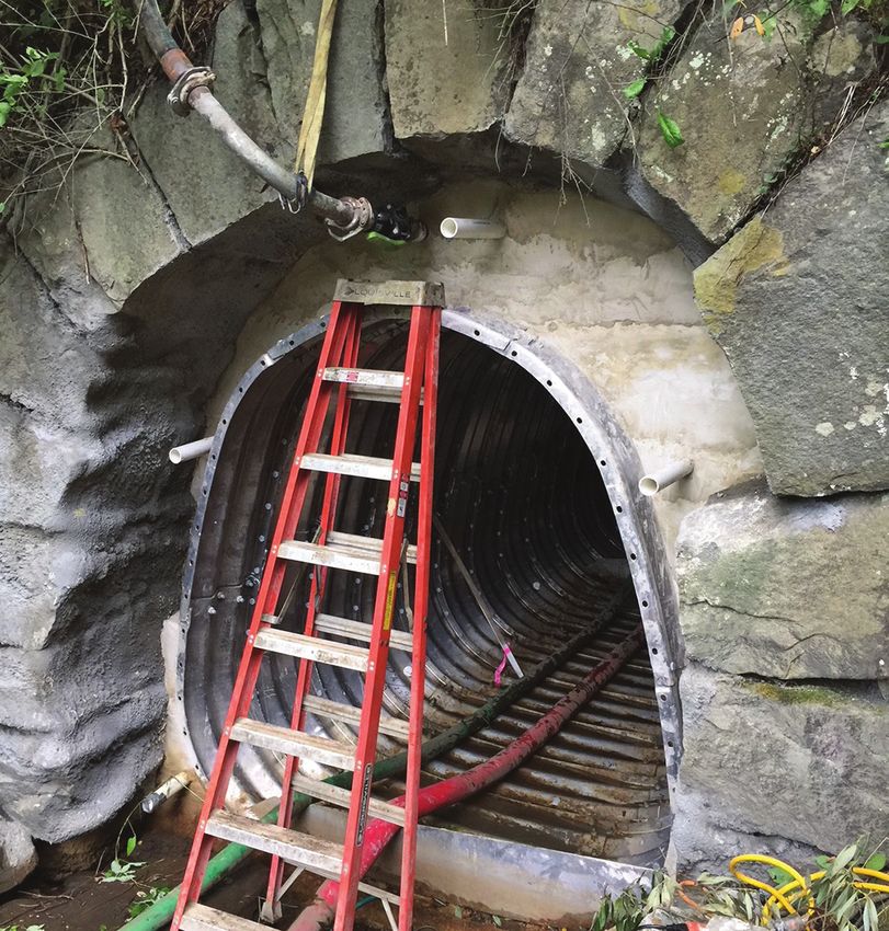
Tunnels can be grouted in several common ways
Annular Space Grout Filling according to the lengths and volumes required, as follows:
Annular space is the area between an object and another
object that is inserted into that object, such as a pipe or • Install similarly to an abandoned pipe filling from
culvert (see Figure 1.6). bulkhead to bulkhead (least expensive method)
• Transport the grout from outside the pipe through pre-
installed grout tubes to the section to be grouted
• Transport the grout in hoses from inside the pipe and
then inject the grout into the void through the pipe by
grout ports (most expensive method)
Ungrouted Grouted
Host pipe Host pipe/
grout interface
Grout
Annular space
Liner pipe
Liner pipe/grout interface
Note: Blocking not shown for clarity
Aerix Industries, used with permission Brierly Associates Corporation, used with permission
Figure 1.6. Annular space grout filling (Maine) Figure 1.7. Ungrouted and grouted annular spaces
Chapter 1. Introduction 7With all three of these procedures, the LCC installer
should be heavily involved in determining the best
method based on experience, equipment, and personnel
to ensure a complete fill with properly specified materials.
Storage tank and mine fills are very similar to pipe and
annular space fillings but with the potential for much
larger volumes of LCC.
Foundation Fills
Sometimes a foundation has unacceptable settlement
issues or voids that require filling (see Figure 1.8).
© 1988 Elastizell Corporation of America, used with permission
The concepts of void filling and the net load design Figure 1.8. Foundation fills (Florida)
method are utilized for foundation fills as well, depending
on the intent of use. Here are some examples of types of
foundation fills:
• Perimeter Fill/Backfilling—New structures are often
installed closely adjacent to a shored hole in the
ground. When the building is complete, the gap
between the building and the shoring needs to be filled.
LCC, with its large volume capability and flowable
nature, fills this void quickly and inexpensively.
• Settlement Reduction/Mat Foundation—The entire
foundation area is excavated based on the net load
design method and replaced with LCC. The foundation
is then installed on top of the LCC surface. Runway Safe Group, used with permission
Figure 1.9. Energy arresting systems (West Virginia)
• Difficult to Access Location—In foundation repair work,
fill is sometimes needed in a basement that is difficult to
system is a bed of engineered LCC built at the end of a
access. With the long-distance pumping abilities of LCC,
runway to reduce the severity of the consequences of a
a hose can be run from the LCC production site to the
plane leaving the end of the paved runway that has been
dispensing location with little difficulty.
adopted by the Federal Aviation Administration (FAA) for
• Insulation Fill—A layer of LCC is placed below a use in airports around the country (FAA 2012).
foundation to increase the insulation value between the
Many years of design, testing, and approvals are required
earth and the structure.
before the manufacturing of these precast elements.
Sea level rise and elevation raise fills are similar to
foundation backfills but may be entirely above grade. Retaining Walls and Precast Wall Panels
Elevated LCC seawalls and bulkheads are a type of When used as a lightweight backfill in place of granular
coastal armoring that can protect shorelines from strong soil, LCC is ideally suited for retaining wall applications
wave action. These types of fills can protect existing where lightweight vertical embankments are required.
development from rising water due to storm surge and When used in conjunction with precast wall panels, these
baseline sea level rise. This geotechnical application systems are designed based on the geotechnical properties
involves formwork and buoyancy considerations. of the soil being retained. When LCC is substituted for
As mentioned, LCC can be an effective material in soil backfill, current practice is to conservatively design
simplifying foundation designs for numerous applications. the walls as if the LCC was a granular material using its
specific unit weight and internal friction angle. Cohesive
Energy Arresting Systems strength in the LCC is conservatively ignored in soil
In this application, LCC blocks or panels are used as a retaining wall designs; however, the appreciable cohesion
kinetic energy dissipating system. While essentially forming in LCC is permanent and provides an additional FOS in
a runaway truck ramp for airplanes (see Figure 1.9), this such designs.
8 Guide to Lightweight Cellular Concrete for Geotechnical ApplicationsThroop Lightweight Fill, used with permission Cell-Crete Corporation, used with permission
Figure 1.10. Placing LCC backfill behind precast wall panels Figure 1.11. Lightweight dam and levee structural fills
(California) (California)
Precast concrete wall systems have been used extensively settlement. Due to the low permeability and monolithic
on LCC embankment installations (see Figure 1.10). nature of LCC, failures due to scour, piping, and wash-
These systems are typically reinforced with lateral metal out are decreased in a levee structure.
or plastic reinforcement extending from the back of the
walls to the design embedment. Walls of this style are Landslide Repair and Slope Stabilization
proprietary and typically designed by the manufacturer Landslides can be rapid, dangerous failures causing
of the wall system according to its proprietary testing extreme issues for those involved. If a slide is small,
and system parameters but following the design rules traditional and simple methods of soil excavation and
for mechanically stabilized earth (MSE) walls stipulated slope regrading are likely to be applicable. However,
by the American Association of State Highway and if a slide is massive, unstable soil removal becomes
Transportation Officials (AASHTO). LCC is treated inapplicable and too expensive. One method of dealing
as soil for MSE wall design purposes, with unit weight with large slides is to stabilize the site (through piers,
and friction angles dependent on the class or estimated tiebacks, dewatering, etc.) and leave the soil in place.
absolute volume design mix of LCC. These walls made of Alternatively, LCC can be used at the crown/head scarp
LCC are a very cost-effective method of creating vertical of the slide area to reduce the driving force from the
faces, especially if soft soils are involved, accelerated weight of the existing soil (see Figure 1.12).
construction is necessary, or adjacent utilities or
structures are present. By removing the top of the slide area and replacing it
with LCC, the mass is reduced, the grade is restored,
Lightweight Dam and Levee Structural Fills and the driving force acting on the slide mass is
significantly reduced.
Lightweight dam and levee structures are often installed
in regions of deep soft sediments where settlement can
be a major problem. LCC can address this challenge
by being installed in the section of the levee below the
surface while repairing a levee and filling it back to the
design grade (see Figure 1.11).
Calculations pertinent to this LCC application again use
the net load design method to avoid increasing the weight
on the deep soft soils. The LCC section can be placed
at any level to achieve the weight reduction, and it is
important to investigate its buoyancy effect to determine
the appropriate location within the levee or dam to place
the LCC. The LCC layer is placed under a designed
amount of heavy soil, incorporating helical anchors
or pavement to keep the structure stable during high
water, with the advantage of achieving weight reduction © 2019 Cell-Crete Corporation, used with permission
year-round, thereby reducing or eliminating any future Figure 1.12. Landslide repair and slope stabilization (California)
Chapter 1. Introduction 9Controlled Density Fill
Controlled density fill (CDF), including CLSM, flowable Typical unconfined compressive strengths are between
fill, slurry cement, two-sack slurry, or sand slurry, is 50 and 150 lb/in2 (0.34 and 1.03 MPa), making CDF
supplied all over the country by ready-mixed concrete stronger and more stable than soil but still excavatable
providers as a compacted backfill replacement in trenches with conventional construction equipment. LCC makes
or under foundations (see Figure 1.13). an excellent CDF material because it can be used in many
of the same applications.
LCC is increasingly cost-effective as the installed volume
increases. When comparing the applicability of LCC
against that of CDF, the following should be considered:
• Price
• Flowability
• Distance to ready-mixed concrete plant
• Availability of water
• Pumping requirements
• Buoyancy of fill
• Project size
• Placement time
PCA
Figure 1.13. Controlled density fill • Traffic access to site
10 Guide to Lightweight Cellular Concrete for Geotechnical ApplicationsChapter 2. Physical Properties
While LCC is usually comprised of only portland Within 8 to 24 hours, depending on the ambient
cement, water, and air provided through a preformed conditions (temperature, precipitation, wind, etc.) and
foam, a vast number of possible mix designs can achieve mix design, the placed LCC changes from a fluid to a
the desired engineering properties. The introduction solid. The density of the hardened LCC is approximately
of supplementary cementitious materials like fly ash the same as its cast density, but due to the process of
or slag, along with chemical admixtures and aggregate cement hydration and water loss through evaporation, the
(fine, coarse, or lightweight), into the LCC to change the hardened density may be slightly lower. The solids in the
fresh and hardened properties adds to the complexity of placed LCC are permanent, but the moisture content does
characterizing its physical properties. vary. The cast density is utilized to represent the density
of the LCC provided. Wetting or drying over the lifetime
The material properties discussed in this chapter are of the product changes its actual field density. While
based on research conducted throughout the world over drainage by itself will not completely prevent density
many years. Proper mix design and construction plays fluctuation, when these fluctuations are unacceptable,
an important role in determining these engineering providing a sealed surface that does not allow additional
properties. Chapter 4 of this guide, Mixture Design, water in may be required. Any sealer used should be
provides some guidance on mix design specifics. approved by its manufacturer for use with LCC.
Fresh Properties In-Place Density
LCC is normally made by combining portland cement, The term dry density is undefined in LCC applications
water, and air through preformed foam (with additives and should be avoided due to its potential ambiguity.
occasionally incorporated) in a mixing chamber. Once Specification writers often incorrectly refer to the final
mixed and in its fresh state, the LCC material is self- in-place density of the LCC after it cures as its dry density.
consolidating and highly fluid, with water/cement (w/c) While geotechnical engineers want to know how much the
ratios ranging from 0.45 to 0.80. Foam manufacturers overall fill weighs in long-term conditions for settlement
provide recommendations given that water content and consolidation calculations, the LCC installer can
significantly affects many properties of LCC, and only control the density at the time of placement. The
especially its strength and viscosity. designer can control the changes in moisture content over
the lifetime of the product by specifying sealers, the finish
Cast Density slope on grade, and drainage systems.
Field measurements of the unit weight, or density
Because the installer can only be responsible for density
(mass per unit volume), along with the known w/c
measuring during LCC placement, the installer should
ratio of the fresh LCC mixture, are the primary quality
not be held responsible for final long-term density
control mechanisms (Hoff 1972). LCC is typically
after placement. While long-term density may change
sampled from a flowing hose using a sample bucket, and
depending on, for example, whether proper drainage or
measurements are taken frequently during production.
surface sealing has been incorporated into the system,
The wet density of placed material may be evaluated
initial and long-term densities do not vary dramatically in
using the recommendations in ASTM International
the field when compared to cast densities.
(ASTM) C796, Standard Test Method for Foaming
Agents for Use in Producing Cellular Concrete Using Oven-Dry Density
Preformed Foam.
The term oven-dry density can be useful, but it is not
This measurement of the wet LCC is referred to as the typically reported unless requested. While it is never
cast density and is the density that should be used in the recommended to oven-dry samples of LCC that are to
specification and design of the LCC project. The installer be tested for unconfined compressive strength analysis,
may also take samples of fresh LCC material from the the oven-dry density can be a useful parameter to back-
placement area, where material pools, or at the end of the calculate the cast density. During cement hydration, the
hose within 30 minutes of installation to ensure densities oven-dry density will increase slightly; however, once the
are in accordance with the design and that air voids cement has completely hydrated, the oven-dry density
are not dissipating, which can result in an unexpected will be constant over the lifetime of the LCC. Oven-dry
increase in density. density can be determined as follows (Equation 1):
Chapter 2. Physical Properties 11Oven-dry Density (lb/ft3) = Cast Density (lb/ft3) ÷ (1 + Moisture Content (%))
(1)
Oven-dry Density (kg/m3) = Cast Density (kg/m3) ÷ (1 + Moisture Content (%))
As an example, the oven-dry density for a 24 lb/ft3 (384 Additional information on proper construction practices
kg/m3) sample of LCC could be as light as 16 lb/ft3 (256 is given in Chapter 5.
kg/m3). Determining LCC oven-dry density through
testing provides an indication of the cement content The viscosity of LCC is variable because of its thixotropic
and can be useful to the engineer who is overseeing the properties (having a viscosity that decreases when a stress
placement operation or as an investigative tool should is applied, as when agitated). The fresh cement pastes
problems arise. in LCC become fluid when agitated but restore their
structural form when at rest. This is because cement pastes
Viscosity experience microstructural changes with time due to the
particles’ flocculation and cement hydration (Quanji
One of the primary reasons for using LCC is its ability
2010). With LCC, the flowability can be maintained
to flow, or its viscosity. Low viscosity allows for long-
for extended periods if agitation continues, as with
distance placements and nearly self-levelling installations.
continuous pumping on a single line where the entire
The viscosity of LCC, like any cement-based product,
mass is moving. However, there is a limit to how long the
is primarily based on its water content. However, in
LCC remains stable with time and agitation. Segregation,
LCC, the air bubbles are also considered. It is generally
where the cement slurry settles and leaves the foam at the
understood that the air bubbles increase flowability by
surface, can occur on extended placements and should
acting as tiny ball bearings within the fill.
be avoided. Segregated areas are often found the next
The viscosity of LCC is often incorrectly specified day by the observation of a crunchy/foamy top, and the
and measured utilizing grout measurement tools that segregated areas should be removed and replaced.
are not appropriate for LCC from the U.S. Army
Corps of Engineers (USACE) or ASTM International. Lateral Fluid Pressure
These flowability measurements are often referred to LCC is placed as a fluid. During placement, the hydrostatic
as viscosity measurements and include ASTM C939, force exerted should be based on the actual cast density
Standard Test Method for Flow of Grout for Preplaced- of the LCC. If a wall or shoring is being backfilled with
Aggregate Concrete (Flow Cone Method); ASTM LCC, it should be designed to ensure that it can support
C1611, Standard Test Method for Slump Flow of Self- the wet fluid. LCC is typically placed in 4 ft (1.2 m) deep
Consolidating Concrete; and ASTM D6103, Standard lifts; however, thicker and thinner lifts are also common.
Test Method for Flow Consistency of Controlled Low Given that LCC stiffens over time, the hydrostatic force
Strength Material (CLSM). completely disappears as the product solidifies into its final
form. Formwork may be removed after the material has
While these procedures are excellent measurements of fully solidified into a homogenous mass.
flowability for normal-weight flowable fill and grouts and
are traditionally used to accept a product before attempting Set Time
to pump into long pipes or similarly constricted locations, LCC is a concrete product, and most of the studies
LCC does not fit well with these established tests. Gravity appropriate for types of cement and concrete also apply
is a key component to the accuracy of these tests, and LCC to LCC. LCC may perform differently in varying
has a density of 1/3 to 1/4 of cement slurry, for which the conditions, with the change factors being agitation,
tests are designed. The tests often provide higher viscosities temperature, and mix design. Fresh concrete is a
than would be expected due to gravity not pulling the thixotropic material that liquefies when energy is applied.
lightweight product through the hole or spreading it Just as ready-mixed concrete trucks continually spin
thoroughly enough. their load to keep the concrete in a fluid state, LCC also
benefits from agitation.
Ultimately, the true test of flowability for LCC is the
measurement of pumping pressure as the product is While an exact set time does not exist for LCC, a
pushed through a hose. Maximum pumping pressure practical set time of two to four hours may be assumed
allowances for project conditions should be developed and for a fill such as a foundation placement or other large-
monitored during placement. Maximum pumping times volume, low-energy, open-top fills. Low-energy fills are
for placements into constricted areas such as abandoned large areas where the entire mass is not in motion and
pipes and annular spaces should be closely monitored. subareas can start setting up prior to completion.
12 Guide to Lightweight Cellular Concrete for Geotechnical ApplicationsIn pipe work, the entire mass is being agitated because The actual diameter of the air voids in fresh LCC depends
the pump is pushing the LCC; therefore, set issues do on the mixing techniques and materials employed. Held
not occur until pumping stops. If the set time is a critical in the hand, it is noticeably lightweight, and density
factor, the installer should evaluate the placement size, differences among samples are readily apparent. The
specific mix, and techniques and compare them to the strength of the residual matrix creates the beneficial
project specifications. This challenge is often resolved by properties found in the final product. The water is
creating smaller cells for placement or by incorporating set utilized during cement hydration, and the preformed
retarding admixtures that are compatible with the LCC. foam is absorbed into the mix, leaving air voids visible to
the naked eye. The cured LCC appears either wet or dry,
Hardened Properties which varies with drying, depending on its water content.
The hardened properties of LCC are the properties that Strength
the engineering community uses for the service life of the
LCC is very strong compared to the material, typically
project. These are the properties of the final product and
soil and compacted aggregates, that it replaces in the
indicate how the product performs when in the structure.
geotechnical environment. A 30 lb/ft3 (480 kg/m3)
The most common hardened properties are unit weight
sample of LCC has a minimum unconfined compressive
and unconfined compressive strength, which should
strength of 40 lb/in2 (0.28 MPa), which corresponds
be measured on every job. Most of the other hardened
to a 2.9 ton/ft2 (0.28 MPa) bearing capacity. Table 2.1
properties, such as air content, permeability, sorption,
provides a summary of industry-accepted values for
modulus of elasticity, and others, are typically not tested
maximum cast density, 28-day minimum unconfined
unless specifically requested by the design engineer.
compressive strength, and bearing capacity that can be
Hardened Description expected for typical LCC mixes used in the US.
Once LCC has been in place for 8 to 24 hours and the Actual LCC mix properties should always be tested prior
final set has taken place or the LCC has hardened, it looks to installation.
like pumice or volcanic tuft (uniform lava rock). It is gray
colored and consists of a portland cement matrix filled The compressive strength, shear strength, resilient
with tiny, round, stable air voids, or vesicles, approximately modulus, and California bearing ratio (CBR) of
0.04 in. (1.0 mm) in diameter (see Figure 2.1). LCC vary due to factors such as cement quality, type
of cement, density, foam quality, w/c ratio, mixing
equipment, sand-cement ratio (if sand is added), mix
intensity, production and placement temperatures, and
additives or admixtures. Several other factors can be
added to this list because, while LCC has only three
primary components (cement, water, and air), the
number of mix variables is immense.
Table 2.1. Physical properties of LCC
Maximum cast Minimum Bearing
density compressive strength capacity
lb/ft3 kg/m3 lb/in2 MPa ton/ft2 MPa
24 385 10 0.07 0.7 0.07
30 480 40 0.28 2.9 0.28
36 575 80 0.55 5.8 0.56
42 675 120 0.83 8.6 0.82
50 800 160 1.10 11.5 1.10
© 2014 Elastizell Corporation of America, used with permission Source: ACI 2006
Figure 2.1. Vesicles/air voids
Chapter 2. Physical Properties 13The study divided the 60 samples into six groups of 10.
The large number of mix variables leads to an inability The six groups were then cured in three different ways.
to make design decisions based entirely on material Half of the groups were sulfur capped and half were not;
property values from the tables, figures, and equations 20 were cured wet, 20 were cured dry, and 20 were cured
provided in this document. The information presented per the procedure in ASTM C495. Each of the six groups
tested consistently for strength, proving that a uniformly
is given to provide guidance only, and the engineer
made/cured LCC could obtain an anticipated strength.
is encouraged to conduct the necessary testing and The most informative part of the results was that the
consultation with the installer and/or manufacturer to curing process was critical. The strength values obtained
determine the appropriate mixture design for achieving from the wet- and dry-cured samples were very similar,
the specified material property requirements. while the samples cured with the ASTM C495 procedure
achieved nearly twice the strength of the others. This
showed that properly following the ASTM C495
A study was conducted in California to evaluate a large
procedure is critical for laboratories measuring LCC
data set of more than 3,000 LCC test samples under
samples for unconfined compressive strengths.
many different conditions (Siebold and Tootle 2016). The
raw data were evaluated, and the unconfined compressive Cohesion and Friction Angle
strengths ranged from one to three times for the same
In one study, laboratory soil tests were conducted on
density (i.e., 30 lb/ft3 [481 kg/m3] density equated to 50
LCC samples having four different densities; shear
to 150 lb/in2 [0.34 to 1.03 MPa] unconfined compressive
strength parameters, coefficients of permeability, and
strength). This is acceptable for a geotechnical fill when
at-rest earth pressure coefficients were measured (Tiwari
a minimum strength is all that is required. However, this
et al. 2017). Unconfined compressive strength and
might not be acceptable in applications when the actual
undrained strength properties (total friction angle and
strength and its accompanying failure mechanism must
cohesion intercept) of partially saturated materials
be known.
were found to be dependent on the density of the
The study was conducted to simply evaluate the ability LCC sample. However, the effective friction angle
of LCC material to be consistent enough for structural and cohesion intercept of the saturated materials were
applications. The intent of the study was to show that 60 independent of the test unit weight over the range of
samples, all from the same batch, would consistently test stresses tested. The effective friction angle and cohesion
the same. This would prove that LCC mixes with near- values of the LCC materials determined from direct
identical strengths could be repeatedly made if required simple shear tests were 35 degrees and 36 kPa (5.2 lb/
and that variables, when held constant, could produce a in2), respectively, as shown in Table 2.2.
consistent product.
Table 2.2. Friction angles and cohesion values for LCC
Unconfined Friction angle for Cohesion for Friction angle Cohesion
Material compressive partially saturated partially saturated for saturated for saturated
strength (kPa) conditions (degrees) conditions (kPa) conditions (degrees) conditions (kPa)
Class II-Batch 1 19 408 35 36
265–1,657
Class II-Batch 2 20 187 35 36
Class IV 628–2,765 21 615 35 36
7.1 kN/m³ cast
8,979–10,845 22 820 35 36
unit weight
8.6 kN/m³ cast
10,729–13,406 21 1,174 35 36
unit weight
1 kPa = 0.145 lb/in2
1 kN/m3 = 6.423 lb/ft3
Source: Tiwari et al. 2017
14 Guide to Lightweight Cellular Concrete for Geotechnical ApplicationsYou can also read