MEDUSA: a Multi-Environment Dual-robot for Underwater Sample Acquisition - Spiral@Imperial College London
←
→
Page content transcription
If your browser does not render page correctly, please read the page content below
IEEE ROBOTICS AND AUTOMATION LETTERS. PREPRINT VERSION. ACCEPTED MAY, 2020                                                                                 1

      MEDUSA: a Multi-Environment Dual-robot for
           Underwater Sample Acquisition
                Diego Debruyn1 , Raphael Zufferey1 , Sophie F. Armanini1 , Crystal Winston1 ,
                                  André Farinha1 , Yufei Jin1 and Mirko Kovac1,2

   Abstract—Aerial-aquatic robots possess the unique ability of
operating in both air and water. However, this capability comes
with tremendous challenges, such as communication incompati-
bility, increased airborne mass, potentially inefficient operation
in each of the environments and manufacturing difficulties. Such
robots, therefore, typically have small payloads and a limited
operational envelope, often making their field usage impractical.
We propose a novel robotic water sampling approach that
combines the robust technologies of multirotors and underwater
micro-vehicles into a single integrated tool usable for field oper-
ations. The proposed solution encompasses a multirotor capable
of landing and floating on the water, and a tethered mobile
underwater pod that can be deployed to depths of several meters.
The pod is controlled remotely in three dimensions and transmits
video feed and sensor data via the floating multirotor back
to the user. The ‘dual-robot’ approach considerably simplifies
robotic underwater monitoring, while also taking advantage of
the fact that multirotors can travel long distances, fly over ob-
stacles, carry payloads and manoeuvre through difficult terrain,
while submersible robots are ideal for underwater sampling or
manipulation. The presented system can perform challenging
tasks which would otherwise require boats or submarines. The
ability to collect aquatic images, samples and metrics will be
invaluable for ecology and aquatic research, supporting our
understanding of local climate in difficult-to-access environments
[Video attachment: https://youtu.be/v4xWmEHUSM4].
  Index Terms—Index TermsEnvironment Monitoring and Man-
agement Index TermsAerial Systems: Applications Index Terms-
Marine Robotics Index TermsField Robots Index TermsMulti-
Robot Systems Index TermsSoft Sensors and Actuators                             Figure 1.     Photograph of the MEDUSA system: the multirotor robot is
                                                                                floating, while the pod has been partially uncoiled and is moving underwater.

                          I. I NTRODUCTION
                                                                                long periods of time like a submersible. Aerial-aquatic robots,
M      ULTI-MODAL robots are able to move effectively
       in different media (water, ground, air) and transition
between them. This remarkable capability, inspired by nature,
                                                                                specifically, could vastly facilitate operations involving water
                                                                                sampling or underwater surveying, which currently rely on
                                                                                manpower (e.g. hand-dropped sensors, rope-access to spaces
allows for the advantages of different types of robots to be
                                                                                under oil rigs) or on the complex integration of different vehi-
combined in a single platform. Thus, it becomes possible for
                                                                                cles (e.g. ships carrying deployable submarine robots). Using
the same robot to cover long distances and fly over obstacles,
                                                                                a single multi-purpose vehicle for such tasks instead would
like an aerial vehicle, and move efficiently underwater for
                                                                                lead to more effective data collection as well as improved
  Manuscript received: February 25, 2020; revised: May 5, 2019; accepted:       safety and reduced costs. However, effective operation in –
May 28, 2020.                                                                   and transitioning between – vastly different mediums (water
  This paper was recommended for publication by Editor Youngjin Choi            and air) presents a considerable challenge, which continues to
upon evaluation of the Associate Editor and Reviewers’ comments. This
work was funded by EPSRC (award no. EP/R009953/1, EP/L016230/1                  hinder the development of aerial-aquatic robots for real-world
and EP/R026173/1), NERC (award no. NE/R012229/1) and the EU H2020               applications.
AeroTwin project (grant ID 810321). Mirko Kovac is supported by the Royal          Most aerial-aquatic robots developed to date [1], [2] fall into
Society Wolfson fellowship (RSWF/R1/18003).
  1 All the authors are with the Aerial Robotics Laboratory, Imperial College   the fixed-wing or rotating-wing category, or involve hybrid
London, UK. m.kovac@imperial.ac.uk                                              fixed/rotating-wing solutions [3], [4].
  2 Mirko Kovac is also affiliated with the Materials and Technology Center
                                                                                   Fixed-wing vehicles [5], [6], [7], [2], [8], [9], [10] have
of Robotics at the Swiss Federal Laboratories for Materials Science and
Technology, Switzerland.                                                        the advantage of fast deployment and longer flight ranges,
  Digital Object Identifier (DOI): see top of this page.                        but both air-water transitioning and underwater locomotion
2                                                                 IEEE ROBOTICS AND AUTOMATION LETTERS. PREPRINT VERSION. ACCEPTED MAY, 2020

                     A
                                                                                                                        C
                                                                          B1

                                                                          B2

Figure 2. Schematic of the operation principle of the dual system. A. The flying module carries the pod (yellow) to set location. B1. The flying module
lands on the water surface and floats due to buoyancy elements. B2. The coiler subsystem (blue) releases the tether and the pod moves vertically (buoyancy
control) and horizontally (jet) to reach the target underwater location. Live video is transmitted and a sample taken. C. The tether is coiled again and the
drone flies back to the user.

are challenging to achieve. Traditional fixed-wing take-off                    While robots face different challenges, the same principle
and landing on water requires relatively extensive areas of                    can be applied, where the respective strengths of two robots
calm water, which are not always available. Furthermore,                       compensate for each other’s weaknesses.
transitioning to or from a fully submerged state involves either
high power density propulsion and impact-resistant structures                     One solution that has been suggested, in a somewhat
– for impulsive transitions – or high-accuracy control – for                   similar vein, is the use of low-flying quadrotors dropping
slow transitions. Long-duration missions likewise present a                    rope-attached sensors into the water and then retracting them
challenge as most fixed-wing vehicles are optimised for flight                 again [17]. This is a relatively simple approach but is con-
and hence have limited underwater locomotion capabilities.                     strained by the short battery time characteristic of quadrotors.
                                                                               Moreover, no control is provided over the positioning of the
   Multirotors, by contrast, can provide a simpler alternative,                dropped sensors in the water.
often made from off-the-shelf components. Due to their verti-
cal take-off and landing capability, they can land on water                       In this paper, we propose a new solution for robotic water
and sink, without requiring added design features. Several                     sampling, comprising a submersible pod tethered to a quadro-
multirotors have achieved a degree of aerial-aquatic mobil-                    tor. The quadrotor flies to a designated location, lands on
ity [11], [12], [13], however these vehicles have a short                      the water surface and deploys a pod to collect measurements.
flight time and range when compared to fixed-wing solutions.                   Landing on the water surface, as opposed to hovering above it,
While underwater propulsion can be achieved using the same                     allows for longer-duration missions when compared to existing
propellers as for flight, this comes at a performance cost and                 aerial robot-based systems, as the quadrotor can float passively
does not always lead to effective locomotion.                                  while the pod performs measurements. When compared to
   Most existing work stops short of demonstrating a full                      single-robot systems, the advantage of our system lies in its
mission cycle, focusing on specific operation phases or on                     modularity and ease of development. The quadrotor is based
simulations [14], [15]. This points to the high complexity of                  on off-the-shelf components, so it does not need to be designed
the proposed solutions, especially for long-duration underwa-                  and manufactured from scratch, and remains outside the water,
ter missions, and has prompted some research into simpler                      hence requires no waterproofing. Moreover, single-robot sys-
approaches. Rather than designing a single robot capable of                    tems designed to collect data underwater still face challenges
operating efficiently in both environments, one alternative is                 with demonstrating air-water transition, controlled flight and
to use a pair of robots inspired by the symbiotic relationships                controlled underwater locomotion in a single system [18].
sometimes found in nature.                                                        Our contributions include the following: (i) a novel ap-
   Many animals develop such relationships to overcome their                   proach for robotic water sampling, that is simpler and better
natural morphological shortcomings. An example is the rela-                    suited for field testing than available methods, (ii) develop-
tionship between remoras and sharks. By attaching itself to a                  ment of communications, electronics and control frameworks
shark, the remora is able to travel long distances while being                 for a symbiotic dual-robot system, (iii) implementation of a
protected by the shark and expending only minimal amounts                      new prototype (MEDUSA: Multi-Environment Dual-robot for
of energy. At the same time, the remora eats bacteria or                       Underwater Sample Acquisition, shown in Fig. 1) validating
parasites that have grown on the shark’s skin, which helps the                 the proposed concept, and (iv) demonstration of the operation
shark avoid infections [16]. In nature, symbiotic relationships                of the new system in both a lab environment and outdoor field
develop out of a need for food, protection and/or hygiene.                     tests.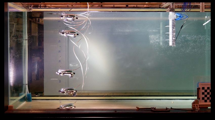
DEBRUYN et al.: MEDUSA: A DUAL-ROBOT FOR UNDERWATER SAMPLE ACQUISITION 3
A ΔV B
Jet pumps Pressure vent
Soft
Dome
Membrane
Jet flow clamp Dome 3D Nylon
Plate clamp Silicone
PMMA
Base plate
with
electronics Water
pressure
sensor Air pressure pump
Electrovalve Differential Interface
pressure
sensor Waterproof dome Tether to surface
C DEPTH CONTROL PRESSURE CONTROL SWITCH LOGIC SYSTEM
∆Perror uactuators Pump
Depth PID PID
∆Psetpoint 1 Valve ∆P PW
Setpoint
∆Pmeasure
Dmeasure = f(PW)
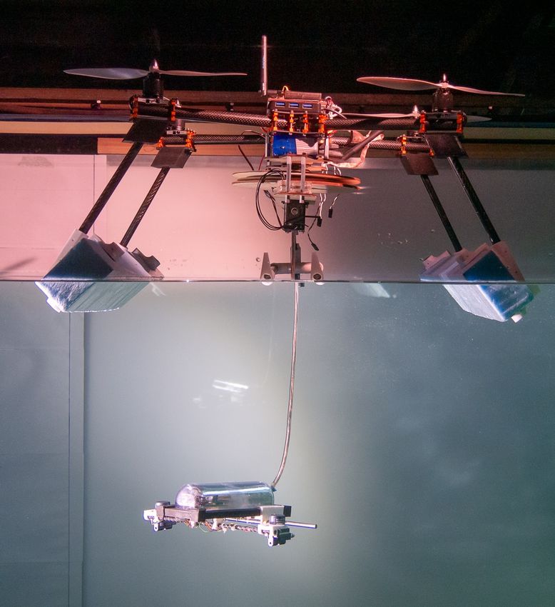
Figure 3. A. Side view of the underwater pod with its main internal components. B. Seal clamp structure. C. Depth control schematic.
II. D ESIGN Slip Ring
Electronics
A. Operation Principle and Envelope
The MEDUSA symbiotic robot system is specifically de- Cable attachment
signed for water sampling in difficult-to-reach locations. As
shown in Fig. 2, the system consists of a quadrotor that can
fly to specific locations, land on the water and deploy a smaller Frame
robot which collects water measurements or samples. The
smaller robot (hereafter ’underwater pod’) has 3 controlled Pulley 1
Dynamixel
degrees of freedom. It controls its depth through inflation of Pulley 2
Silicone tube Coil Plates
a soft membrane, its forward motion via the thrust produced
Curved Tether
by two pumps on the outside of its body, and its orientation ribbon Air gap
cable
around the vertical axis via a thrust differential between the
same pumps. This allows the system to travel successfully to
Figure 4. CAD view of the coiling mechanism installed at the base of the
different difficult to reach and potentially far apart locations, X-frame quadrotor.
and to collect various water samples or measurements within
a single mission. The pod is connected to the quadrotor by a
5 meters long tether, which constrains its operating envelope The underwater pod depends entirely on the tether for
to a spherical cap with slightly under 5 meters radius. power, commands, relaying back data, live video and air
A specific scenario where MEDUSA can operate and per- supply. A design constraint for this system is its maximum
form better than other aerial aquatic solutions is the monitoring depth, which has a direct impact on the required tether length.
of coral reefs. As these environments are normally close to In order to have an operation envelope of a spherical cap
shore, the short mission range inherent to using a quadrotor of 5 m radius, an equivalent length of tether needs to be
is not critical. Moreover, these environments are very unstruc- reliably coiled before flight and uncoiled once in the water.
tured and normally encountered at shallow depths. The five- Furthermore, to minimise the impact of the tether on the
metre range of the tether is thus sufficient for the mission and pod motion, its stiffness needs to be reduced as much as the
the underwater pod can manoeuvre the intricate features of application permits and its buoyancy must be close to neutral.
the reefs due to its small form factor and nimbleness. Thanks The developed custom tether, shown in Fig. 4 (bottom),
to the features mentioned, water samples can be obtained in consists of a 6 mm outer diameter silicone tube that shields
the vicinity of relevant biomes that would otherwise not be the cable from sea-water and is bonded at its extremities. It
possible to access remotely. contains a curved ribbon cable by Cicoil. Every strand is
made from a twisted copper wire with silicone insulation,
B. Deployment Flying Vehicle chosen with a 1 A specification. The ribbon cable leaves an
The flying platform is a custom quadrotor of approximately air gap within the silicone tube that serves as a channel for air
1 kg and a payload of 800-900 grams. The double 2D flow. The copper strands limit the minimum bending radius,
plate frame is well-suited to affix the bottom-mounted coiling permitting unrestricted air flow at all times. The end of the
system, as shown in Fig. 4. tube is sealed onto the air pump resting in the pod.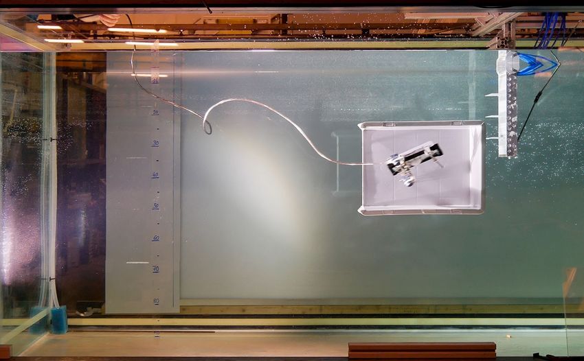
4                                                       IEEE ROBOTICS AND AUTOMATION LETTERS. PREPRINT VERSION. ACCEPTED MAY, 2020

C. Underwater Pod                                                   membrane to burst. A second PID controller (‘pressure con-
   The underwater pod consists of two external pumps, which         trol’) takes the difference between the measured differential
steer the pod via differential thrust, and a main cabin, which      pressure and the aforementioned required differential pressure
houses the electronics, pump and membrane needed for ver-           as error signal, and computes the required actuator inputs.
tical locomotion. This pump is sized to withstand pressure 5        While a single signal is computed by the controller, the pod
meters underwater and determines the pod achievable depth.          is controlled by the combination of a pressure pump and a
Inside the main cabin is a microcontroller, which handles           valve. In a final step, the input to each actuator is therefore
communication between the quadrotor and the underwater pod.         determined according to the following logic. If the actuator
The cable that connects the underwater pod to the quadrotor         signal computed by the controller corresponds to an increased
via the coiling unit is used to send high-level commands to the     differential pressure demand, the signal is passed directly to
pod. The actuators, sensors and microcontroller inside the pod      the pump and the valve is closed, allowing pressure to build
are also powered by the quadrotor, with the wires connecting        up. If, on the other hand, a decreased differential pressure is
these systems to the quadrotor’s battery also passing through       required, the pump is set to zero and the valve is opened to
the coiling mechanism. The main cabin is pressurised, reduc-        allow for pressure to be released.
ing structural loads, therefore reducing weight and enhancing
waterproofness.                                                     B. Sensor Payload
   The structure of the pod is shown in Fig. 3.A. Its dimensions       MEDUSA is currently equipped with a camera and absolute
are minimised for the smallest volume possible in order to          pressure sensor, so that underwater images and their corre-
reduce the amount of ballast needed to sink. For that purpose,      sponding depths can be recorded. The camera is physically
the shape of the pod was designed to match the containing           placed in the pod, it thus transmits underwater footage when
components. A semi-cylinder fits well and rests against a rigid     the pod is deployed and aerial footage (fixed heading) when
support plate.                                                      in flight. In future iterations, these sensors could be com-
   The PETG dome is vacuum-formed and has a lip to seal             plemented by salinity, pH, oxygen content, and other water
against the PMMA support plate as shown in Fig. 3.B. The            quality sensors if the mission requires it. A custom water
silicone seal is made from Moldstar 15. It is maintained under      sampling device will also be developed.
pressure through a 3D-printed nylon clamp. The 4 C-Clamp
segments fit against each other to seal the entirety of the
                                                                    C. Electronics, Communication and Inter-System Tether
perimeter. Rubber bands in the corners lock the clamps in
place. This sealing method is reliable (more than 100 opening
cycles), takes 10 seconds to seal and can be rapidly prototyped.
                                                                          433 MHZ
                                                                                       RC                        SBUS
                                                                                                                 PWM                 Pixhawk                                 PWM
                                                                                                                                                     MAVLINK
                III. S ENSING AND C ONTROL
                                                                                                                                                                              ESC
A. Horizontal Actuation and Buoyancy Control                               2.4 GHZ    Wifi                               Companion μC
   The orientation of the underwater pod is controlled by two
                                                                                                                SERIAL
                                                                                                                                                                      Motor
external jets which steer via thrust differential. When the                                                                                               DYNAMIXEL    x4
                                                                                       Vid                                                                Coil
                                                                                                              POWER

                                                                           2.4 GHZ
                                                                                       A
floating quadrotor receives a command to turn the underwater                            NALOG

pod, it adjusts the thrust generated by both of the external jets
in order to rotate the pod. This is presently done via open-
                                                                                                     TETHER

loop commands, however a closed-loop control scheme could
be easily implemented, if a specific orientation is required for
a given mission.
   The vertical locomotion of the underwater pod is controlled                                                              Pressure A                         Pressure B
via buoyancy adjustments. This strategy is inspired by fish,             Camera
who generally control their depth in the water by inflating              module                                                     I2C                               I2C

                                                                                            I/O                            Pod micro-controller
or deflating a bladder inside their body, thus changing their                                     I/O
                                                                                                                              PWM              PWM              PWM
                                                                                                                                                                              I/O

buoyancy. Our underwater pod employs the same technique to
                                                                                                DRIVER A                 DRIVER B         DRIVER B        DRIVER C          DRIVER D
control its buoyancy and resulting depth, using two pressure                                LED                          Jet 1        Jet 2             Pump           Valve
sensors and a pump. Once the pod receives a depth setpoint
from the user, it uses a absolute pressure sensor to determine
its current depth and a differential pressure sensor to determine   Figure 5. Communication and electronics framework showing both the drone
the difference in pressure between the inside and outside of        subsystem (top) and the pod subsystem (bottom), linked by a custom tether.
the cabin. The difference between current depth and desired
depth is fed into a first control component (‘depth control’          The MEDUSA drone comprises a uniformed electrical
block in Fig. 3.C), which determines the differential pressure      network that spans from the flying vehicle to the underwater
required for the pod to attain and maintain the target depth.       mobile pod (cf. Fig. 5). The companion computer runs ROS
The computed pressure request is monitored to ensure that           (Robotic Operating System), which handles high-level tasks
it remains within achievable bounds and does not cause the          and all the control of the system. It interfaces with the coiler
DEBRUYN et al.: MEDUSA: A DUAL-ROBOT FOR UNDERWATER SAMPLE ACQUISITION 5
20 140
subsystem, in charge of coiling and uncoiling the tether. The diff. pressure setpoint
coiler is operated via a dynamixel servoactuator, running as a measured diff. pressure 120
differential pressure [mbar]
15 membrane volume
node in ROS. Two different serial links span from the compan- 100
volume [cm 3]
ion microcontroller to the flight controller (MAVLINK, Micro 10 80
Air Vehicle Link serial communication protocol) and to the
underwater pod using ROSserial. 5 60
The flight controller handles the framework required for 40
multirotor flight. It directly outputs the signals to the four 0
20
Electronic Speed Control (ESC) board that drive the brushless
motors. Additionally, the flight controller relays flight data to -5 0
0 10 20 30 40 50 60
the companion computer via MAVLINK. t [s]
The end user interacts with the flight controller via a
standard 433 MHz radio link which provides kilometre-range
Pod
operation. This connection transmits instructions and manual
control commands and is supplemented by a telemetry link.
The latter serves to send and receive commands that can
change parameters and read system states. Analog video is
broadcasted by radio and requires only one cable in the tether.
IV. R ESULTS AND D ISCUSSION Soft bladder
The developed system was tested both in a controlled Jet
laboratory setting, allowing for extensive underwater charac-
Figure 6. Evaluation of the buoyancy-based actuation mechanism for
terisation, and in realistic outdoor conditions. The experiments vertical motion. A. Measured membrane volume versus differential pressure
aimed to demonstrate the locomotion and manoeuvring capa- for different pressure setpoints. B. View of the inflated membrane during
bility of the system in both the horizontal and the vertical experiments.
plane, the effectiveness of the depth control system, and the
overall functioning of the robot in realistic outdoor conditions. 15
Furthermore, preliminary tests were performed to assess the Mooney-Rivlin
measured values
efficacy of the membrane-based buoyancy control method
proposed, and a model was developed to yield more detailed
insight into the behaviour of the membrane. The remainder of
this section provides an overview of the main results obtained. 10 14.1
124 cm3 13.5
pressure [mbar]
12.9
A. Membrane-Based Actuation 12.5
As elucidated in Section III-A, the vertical motion of the 12
60 cm3 12
underwater pod is controlled through pressure-based inflation 5 12
and deflation of a soft membrane (as shown in Fig. 6.B). An 12
important preliminary step is to establish whether this type 16 cm3 12
of actuation mechanism is adequate for stable depth control. 10
To evaluate this, we fed the pod a number of differential 5 mbar
pressure setpoints and observed the resulting changes in dif- 0
0 20 40 60 80 100 120
ferential pressure and volume of the deforming membrane.
3
This is equivalent to testing the system with only the inner volume [cm ]
loop ‘pressure control’ component of Fig. 3.C active. The Figure 7. Membrane volume versus pressure: model-predicted and tracking
aforementioned experiments were conducted outside the water data-reconstructed results.
with the pod at rest, so as to provide a clear view of the
inflating membrane. The volume of the membrane at each
time step was computed based on video footage. The inflated of the soft membrane increases as pressure is increased.
membrane is approximated as a spherical cap, whose volume The two variables are approximately proportional up to a
can be computed from its base width 2a and maximum height differential pressure of 10 mbar, after which point the relation
h via the expression, between the two becomes significantly nonlinear, with a strong
1 increase of volume at nearly constant pressure. It can also be
V = πh(3a2 + h2 ). (1)
6 seen that there is a limit to what differential pressures can
be reached. Based on both observations, it was decided to
Subsequent time synchronisation with the concurrent sensor limit the differential pressure to values below 10 mbar, where
measurements provided the corresponding differential pressure the membrane is not in danger of bursting and the relation
in the pod. As anticipated, and clarified by Fig. 7, the volume between pressure and volume is approximately proportional.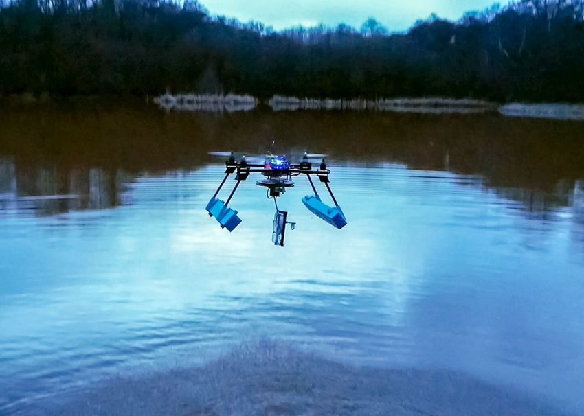
6 IEEE ROBOTICS AND AUTOMATION LETTERS. PREPRINT VERSION. ACCEPTED MAY, 2020
A I
B I
depth [cm]
0
I
II II
-20 II
-40
III
-60
III III
-80 IV
setpoint
IV measurement IV V
-100
0 100 200 300 400 500 600 700 800
V
time [s] V
Figure 8. Vertical actuation and depth control results, showing the pod tracking a number of different successive depth setpoints.
Within this region, the pod can be rapidly stabilised at any respectively. v
given pressure (cf. Fig. 6.A). u 2 2
u ∂ρ + ∂η
u dr ∂r
λ1 = t (2)
∂z 2
1 + ∂r
A B 0.5
ρ
0.4 λ2 = (3)
forward velocity [m]
r
0.3
The equilibrium equations of the deformed membrane yield
0.2
∂T1 1
+ (T1 − T2 ) = Pt (4)
0.1 ∂ρ ρ
0
0 0.5 1 1.5 2 2.5
5 images per second time [s] K1 T1 + K2 T1 = Pn (5)
C where T1 and T2 represent the meridional and circumferential
stresses, Pn represents the stresses normal to the membrane
surface and Pt represents pressure in the transverse direction.
For this problem Pt = 0. Finally, assuming that this is an
incompressible material that can be modelled with a two term
Mooney-Rivlin constitutive relation, we get
λ1 1
T1 = 2C1 h − 3 3 (1 + αλ22 ) (6)
λ2 λ1 λ2
1 image per second
λ2 1
T2 = 2C1 h − 3 3 (1 + αλ21 ) (7)
Figure 9. A. Composition showing maximum rotational control of the robot λ1 λ1 λ2
at 100◦ /s. B. Manual control of the horizontal motion of the robot moving
forward, turning and returning to base. C. Maximum velocity of the robot where C1 and α are constants that come from the constitutive
with jet thrusters at 100%. relationship. This relationship is usually written in terms of
C1 and C2 where α = C1 /C2 .
The above equations were simplified into three first-order
In order to further understand the behaviour of the mem- ODEs using the method described by Yang and Feng [20]
brane, it was modelled as a thin, hyperelastic, incompress- and then solved using a Runge-Kutta algorithm, implemented
ible shell using the formulation developed by Adkins and as in Ref. [21]. Solving these ODEs yields the height of the
Rivlin [19]. The membrane is described using a cylindrical inflated membrane bubble, which can then be used to calculate
coordinate system (r, Θ, z), where each particle on the surface the volume as per eq. 1. The material properties, C1 and α,
of the membrane exists at a point (ρ, θ, η). The stretch ratios could not be found for our particular material (Ecoflex 00-
in the meridional and circumferential directions are λ1 and λ2 , 20), so values for a similar material were chosen as a starting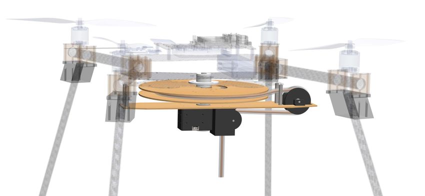
DEBRUYN et al.: MEDUSA: A DUAL-ROBOT FOR UNDERWATER SAMPLE ACQUISITION                                                              7

point, and they were then adjusted to fit our data [22]. The        the range allowed by the tether, reaching a speed of up to
values used to describe the geometry of the membrane and            approximately 0.35 m s−1 (cf. Fig. 9).
the corresponding material constants that came from fitting            While the actuation mechanism does not provide direct
the model to the data are given below.                              control over all degrees of freedom, the combination of vertical
                                                                    and horizontal actuation leads to a comprehensive range of
                            Table I                                 motion. By manoeuvring the pod into a closed space with
                   M ODEL PARAMETER VALUES .
                                                                    a single lateral opening (cf. Fig. 10 left), we for instance
C1 [MPa]                     α    Thickness [mm]   Radius [mm]      showed that narrow confined spaces can be reached, which
0.0039                      0.1         1.1             20          is an important capability for the type of system proposed.

                                                                    D. Outdoor Testing
B. Vertical Locomotion and Control                                     Outdoor field tests were performed on a lake, surrounded
                                                                    by dense forest (cf. Fig. 10). The water conditions were calm,
   The first set of indoor tests was performed in a 1m deep         but there were gusty winds. One of the most critical aspects
water tank, in order to evaluate the effectiveness of the           of an aerial-aquatic robot is the transition from air to water
depth control scheme. These experiments involved placing the        and vice-versa. We successfully demonstrate multiple landings
pod in the water, and successively sending it different depth       and take-offs from the water of the quadrotor carrying the
setpoints to track, while always remaining attached to the          coiling unit and pod. The downwash of the propellers does
quadrotor via the tether. An example of the obtained results        not create significant spray during take-off and in general
is illustrated in Fig. 8, where it can be observed that the pod     no significant difficulties were encountered. The tests suggest
is able to track user-defined depths effectively, and that the      that the robotic concept can function reliably and robustly in
developed buoyancy-based actuation can be used for vertical         realistic and challenging conditions, similar to those that would
manoeuvring. New setpoints are consistently reached within          be encountered in a typical application scenario. Underwater
approximately 5s – a short time, given the relatively slow          operation of the pod is not shown in the reported field tests
motion of the pod in the water.                                     due to the low visibility in the pond (less than 10 cm). This
   Further it was found that, especially when moving down-          would have hindered any visual observation of the position of
wards (to greater depths), the pod develops a slow oscillatory      the pod or any relevant remote video recording.
movement around the target depth. This may indicate that               While the tether is a vital element, containing electronic
the actuation mechanism is unable to fully cancel out all           and pneumatic links and ensuring that the pod can always
oscillatory motion. Nonetheless, the observed fluctuations typ-     be recovered, it also limits the operating range of the system
ically have a magnitude of approximately 2-5 cm. Considering        and may tangle or break. In general, MEDUSA is designed
the intended domain of operation in the range of several            to operate in mild wind and water conditions, where the
metres, as well as the non-ideal experimental conditions,           quadrotor can float in an approximately steady position. The
which inevitably involved some water movement, the attained         envisaged applications would take place in favourable weather
accuracy of the system can be considered substantial despite        or in calm waters, e.g. on lakes.
the aforementioned oscillations. Note that, by contrast, when
moving to smaller depths, the robot appears to stabilise
                                                                                          V. C ONCLUSIONS
more accurately and rapidly. This difference in behaviour is
likely due to the combined pump and valve-based actuation               This article presents a novel concept for automated water
explained in Sec. III-A, according to which increases in depth      sampling in difficult-to-reach locations, based on a dual-
are obtained through valve opening.                                 robot system consisting of a multirotor that can reach remote
                                                                    locations rapidly and land on the water, and an underwater pod
                                                                    that can stream live video and take samples. The proposed
C. Horizontal Locomotion                                            solution significantly reduces the limitations and difficulties
   While large horizontal distances are covered by displacing       typical of single-body aerial-aquatic robots, while still bene-
the quadrotor itself, and horizontal movement of the pod can        fiting from the same advantages. A prototype was developed
hence be limited in range, it is an important asset that the        to demonstrate the approach. The design trade-off and the
pod is able to manoeuvre and position itself within the region      implementation and manufacturing methods required to build
of interest. It may for instance be necessary for a particular      and operate such a system are discussed in the paper. Indoor
mission to approach underwater objects, ranging from oil            and outdoor tests showed that the approach can be applied suc-
platform risers to coral reefs, or even to move underneath or       cessfully in realistic conditions, and that the soft membrane-
inside a structure such as a pipe. In this context, the lateral     based depth controller and jet-based horizontal actuation allow
manoeuvrability and performance of MEDUSA was tested.               for accurate positioning and manoeuvring of the pod. The
   Results show that the jet-based actuation provides sufficient    proposed approach allows for challenging underwater missions
thrust, leading to a manoeuvrability well-suited to the types       to be performed in a simple and robust way, which makes the
of missions envisaged for the robot. As shown in Fig. 9 (left),     method amenable for real-life applications.
the pod can reorient itself rapidly and perform horizontal turns        Future work will further improve the field-readiness and
at up to 100 ◦ /s, as well as reach given target locations within   reliability of the system. A structural revision of the pod,
8                                                                      IEEE ROBOTICS AND AUTOMATION LETTERS. PREPRINT VERSION. ACCEPTED MAY, 2020

Figure 10. (Left) The robot is remotely manoeuvred into a confined space with a side opening of 30 cm (Right) The flying dual-robot platform shown
during a take-off from water returning to the operator. Location: Silwood Park Campus, Imperial College London.

currently manufactured from vacuum-formed shells and 3D-                             [9] R. Zufferey, A. Ortega, C. Raposo, S. F. Armanini, A. Farinha, R. Sid-
printed parts, will permit faster assembly, more reliable water-                         dall, I. Berasaluce, H. Zhu, and M. Kovac, “SailMAV: design and
                                                                                         implementation of a novel multi-modal flying sailing robot,” Robotics
proofing and increased compactness. The geometry of the pod                              and Automation Letters, vol. 4, no. 3, 2019.
can also be optimised for improved hydrodynamics and sta-                           [10] R. Zufferey, A. Ortega, A. Farinha, R. Siddall, S. F. Armanini, B. R.
bility. Additionally, further work will be undertaken to render                          K. G. Nasr, M, and M. Kovac, “Consecutive aquatic jump-gliding with
                                                                                         water-reactive fuel,” Science Robotics, vol. 4, no. 34, 2019.
the system fully autonomous. This will include implementing a                       [11] H. Alzu’bi, I. Mansour, and O. Rawashdeh, “Loon copter implemen-
position controller for the horizontal plane and a vision-based                          tation of a hybrid unmanned aquatic-aerial quadcopter with active
navigation component allowing more elaborate underwater                                  buoyancy control,” Journal of Field Robotics, 2017.
                                                                                    [12] M. M. Maia, D. A. Mercado, and F. J. Diez, “Design and implementation
mission execution. Some form of stabilisation in response to                             of multirotor aerial-underwater vehicles with experimental results,” in
water currents would also be beneficial. Future field missions                           2017 IEEE/RSJ International Conference on Intelligent Robots and
will be undertaken in clear waters.                                                      Systems (IROS), 2017, pp. 961–966.
                                                                                    [13] Z. Ma, J. Feng, and J. Yang, “Research on vertical air–water transmedia
                                                                                         control of hybrid unmanned aerial underwater vehicles based on adaptive
                       VI. ACKNOWLEDGEMENTS                                              sliding mode dynamical surface control,” Int. J. Advanced Robotic
                                                                                         Systems, vol. 15, no. 2, 2018.
   The Multi-Terrain Aerial Robotics Arena is supported                             [14] P. J. Drews, A. Alves Neto, and C. M. F. M., “Hybrid unmanned aerial
through a philantropic gift by Brahmal Vasudevan. The authors                            underwater vehicle modeling and simulation,” in IEEE/RSJ Int. Conf.
also thank the Imperial College London Department of Civil                               on Intelligent Robots and Systems, 2014.
                                                                                    [15] S. F. Armanini, R. J. D. Siddall, and M. Kovac, “Modelling and
Engineering for usage of the hydrodynamics laboratory testing                            simulation of a bioinspired aquatic micro aerial vehicle,” in AIAA
facilities.                                                                              Modeling and Simulation Technologies Conf., Dallas TX, 2019, AIAA
                                                                                         Paper 2019-3115.
                                                                                    [16] P. Kyne, “Occurrence of a sharksucker (’echeneis naucrates’) on a
                                 R EFERENCES                                             northern river shark (’glyphis garricki’) in a tidal riverine habitat,”
                                                                                         Northern Territory Naturalist, vol. 26, p. 21–26, 2015.
    [1] K. H. Low, T. Hu, S. Mohammed, J. Tangorra, and M. Kovac, “Per-
                                                                                    [17] J.-P. Ore, S. Elbaum, A. Burgin, and C. Detweiler, “Autonomous
        spectives on biologically inspired hybrid and multi-modal locomotion,”
                                                                                         aerial water sampling,” Journal of Field Robotics, vol. 32, no. 8, pp.
        Bioinspiration & Biomimetics, vol. 10, no. 2, 2015.
                                                                                         1095–1113, 2015. [Online]. Available: https://onlinelibrary.wiley.com/
    [2] R. Siddall and M. Kovač, “Launching the AquaMAV: Bioinspired design
                                                                                         doi/abs/10.1002/rob.21591
        for aerial-aquatic robotic platforms,” Bioinspiration and Biomimetics,
                                                                                    [18] R. Zufferey, S. F. Armanini, A. Farinha, and M. Kovac, “Adaptive
        vol. 9, no. 3, 2014.
                                                                                         morphology in aerial-aquatic robots,” in Adaptive Motion in Animals
    [3] D. Lu, C. Xiong, Z. Zeng, and L. Lian, “A multimodal aerial underwater
                                                                                         and Machines (AMAM) Conf., 2019.
        vehicle with extended endurance and capabilities,” in Int. Conf. Robotics
                                                                                    [19] J. E. Adkins and R. S. Rivlin, “Large elastic deformations of isotropic
        and Automation (ICRA), 2019.
                                                                                         materials ix. the deformation of thin shells,” Philosophical Transactions
    [4] J. Bian and J. Xiang, “Quuv: A quadrotor-like unmanned underwater
                                                                                         of the Royal Society, vol. 224, p. 505–531, 1952.
        vehicle with thrusts configured as x shape,” Applied Ocean Research,
                                                                                    [20] W. H. Yang and W. W. Feng, “On axisymmetrical deformations of
        vol. 78, 2018.
                                                                                         nonlinear membranes,” ASME Journal of Applied Mechanics, vol. 37,
    [5] R. Peloquin, D. Thibault, and A. L. Desbiens, “Design of a passive ver-
                                                                                         p. 1002–1011, 1970.
        tical takeoff and landing aquatic UAV,” IEEE Robotics and Automation
                                                                                    [21] D. D. Washington, “Efficient methods for analyzing thin membranes
        Letters, vol. 2, no. 2, pp. 381–388, April 2017.
                                                                                         subjected to transverse pressure and undergoing large deformation,”
    [6] J. Liang, Y. Xing, W. Tianmiao, Y. Guocai, and W. Zhao, “Design and
                                                                                         Ph.D. dissertation, 2004.
        experiment of a bionic gannet for plunge-diving,” Journal of Bionic
                                                                                    [22] Y.-Y. Hsu, K. Lucas, D. Davis, B. Elolampi, R. Ghaffari, C. Rafferty,
        Engineering, vol. 10, no. 3, 2013.
                                                                                         and K. Dowling, “Novel strain relief design for multilayer thin film
    [7] J. Moore, A. Fein, and W. Setzler, “Design and analysis of a fixed-
                                                                                         stretchable interconnects,” IEEE Transactions on Electron Devices,
        wing unmanned aerial-aquatic vehicle,” in 2018 IEEE International
                                                                                         2013.
        Conference on Robotics and Automation (ICRA), 2017.
    [8] W. Stewart, W. Weisler, M. MacLeod, T. Powers, A. Defreitas, A. Gritter,
        M. Anderson, K. Peters, A. Gopalarathnam, and M. Bryant, “Design and
        demonstration of a seabird-inspired fixed-wing hybrid uav-uuv system,”
        Bioinspiration & Biomimetics, 2018.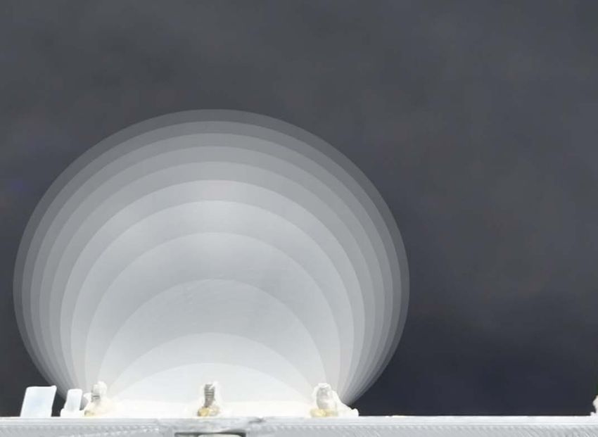
You can also read